Tuned radio frequency identification (RFID) circuit used as a security device for wristbands and package security
US20070125867A1
2007-06-07
11/294,216
2005-12-05
✅ Patent granted
US 7,377,447 B2
2008-05-27
-
-
Thien M Le
2026-09-06
Abstract:
A tamper evident RFID circuit uses a fold section that forms a capacitive element when folded together.
Assignee:
- RCD Technology Corp. 6 🇺🇸 Bethlehem, PA, United States
- RCD Technology, Inc. 1 🇺🇸 Quarkertown, PA, United States
Interested in similar patents?
Get notified when new applications in this technology area are published.
Classification:
G06K19/07758 » CPC main
Record carriers for use with machines and with at least a part designed to carry digital markings characterised by the kind of the digital marking, e.g. shape, nature, code; Record carriers with conductive marks, printed circuits or semiconductor circuit elements, e.g. credit or identity cards also with resonating or responding marks without active components with integrated circuit chips; Constructional details, e.g. mounting of circuits in the carrier the record carrier being capable of non-contact communication, e.g. constructional details of the antenna of a non-contact smart card arrangements for adhering the record carrier to further objects or living beings, functioning as an identification tag
G06K19/07749 » CPC further
Record carriers for use with machines and with at least a part designed to carry digital markings characterised by the kind of the digital marking, e.g. shape, nature, code; Record carriers with conductive marks, printed circuits or semiconductor circuit elements, e.g. credit or identity cards also with resonating or responding marks without active components with integrated circuit chips; Constructional details, e.g. mounting of circuits in the carrier the record carrier being capable of non-contact communication, e.g. constructional details of the antenna of a non-contact smart card
G06K19/07771 » CPC further
Record carriers for use with machines and with at least a part designed to carry digital markings characterised by the kind of the digital marking, e.g. shape, nature, code; Record carriers with conductive marks, printed circuits or semiconductor circuit elements, e.g. credit or identity cards also with resonating or responding marks without active components with integrated circuit chips; Constructional details, e.g. mounting of circuits in the carrier the record carrier being capable of non-contact communication, e.g. constructional details of the antenna of a non-contact smart card the record carrier comprising means for minimising adverse effects on the data communication capability of the record carrier, e.g. minimising Eddy currents induced in a proximate metal or otherwise electromagnetically interfering object
G06K19/07798 » CPC further
Record carriers for use with machines and with at least a part designed to carry digital markings characterised by the kind of the digital marking, e.g. shape, nature, code; Record carriers with conductive marks, printed circuits or semiconductor circuit elements, e.g. credit or identity cards also with resonating or responding marks without active components with integrated circuit chips; Constructional details, e.g. mounting of circuits in the carrier the record carrier being capable of non-contact communication, e.g. constructional details of the antenna of a non-contact smart card part of the antenna or the integrated circuit being adapted for rupturing or breaking, e.g. record carriers functioning as sealing devices for detecting not-authenticated opening of containers
G06K5/00 IPC
Methods or arrangements for verifying the correctness of markings on a record carrier; Column detection devices
G06K19/06 IPC
Record carriers for use with machines and with at least a part designed to carry digital markings characterised by the kind of the digital marking, e.g. shape, nature, code
Description
BACKGROUND OF INVENTIONA passive RFID circuit (transponder) generally consists of a tuned circuit, which often takes the form of a external antenna which receives both power and an information signal from the electromagnetic field emanated by a second system component (RFID reader), and a integrated circuit, which contains the microprocessor and memory components by which the transponder decodes and respond to an interrogation signal.
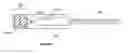
BRIEF DESCRIPTION OF THE DRAWINGSFIG. 1 is a diagram of an RFID circuit of one embodiment.
DETAILED DESCRIPTION OF EMBODIMENTSThe design of the tuned circuit, herein referred to as the “antenna”, can be carefully designed in order to facilitate satisfactory response to the field emanated by the RFID reader. Configuring the antenna such that disruption of the antenna by breaking one of the conductive traces of the antenna may be used to produce a tamper evident RFID device. Such RFID circuits can be used for wristbands and security locking devices, such as package security. The proper configuration and stability of passive components of the antenna (such as resistors and capacitors) can be required to maintain suitable performance of the antenna. A security device may be configured such that tampering with these passive components will cause either impaired or wholly different function of the device. Thus it is possible to configure a tamper evident RFID whose function is altered by configuring the passive components of the antenna. Further the device may be configured such that tampering with the components will likely disrupt several components simultaneously thus rendering the tamper evident nature of the device more robust than one in which tampering disrupts only one component.
FIG. 1 shows an example of a tamper resistant RFID circuit. An RFID circuit of one embodiment can have a substrate 102, antenna portion 104 on the substrate 102 and a fold section 106 on the substrate 102. The fold section 106 can contain an adhesive layer (shaded region). When the fold section 106 is folded together with the adhesive layer, at least one capacitor is created which sets the RF response characteristics of the RFID circuit.
In the RFID circuit 100 of FIG. 1, the elements A0 and B0 with their corresponding elements A1 and B1 can form a pair of parallel plate capacitors in series or parallel (dependent on the absence/presence of conductive link M) with the inductor coil 108 (part of the antenna pattern 104) and integrated circuit, IC. The capacitors can be formed by folding the flexible substrate 102 along the dotted line l, which is secured by an adhesive, such as a pressure sensitive adhesive.
An RFID wristband with a robust tamper evident closure may be formed by the insertion of the strap 108 of the wristband through the hole 106a and effecting the fastening of the wristband by folding the circuit along line l. Any attempt to cut the wristband is likely to sever the circuit that extends through the band if the band is cut in any position. Any attempt separate the adhesively joined sections is likely to disrupt the tuning of the circuit, such as by damaging the capacitors, and render the antenna non-functional. The antenna portion and/or capacitor(s) can be made of a conductive ink material that is susceptible to damage.
The substrate can have printed indicia, such as the line l, along a centerline of the fold section. A strap 108 can fit through the center hole 106a. The RFID antenna portion 104 can extend through the strap portion 108. A connection region can be used to connect the antenna portion 104 to an RFID IC 110. When the strap 108 is adhered to the wristband the RFID antenna portion 104 can extend completely around the wristband such that the wristband cannot be cut off without modifying the RF response of the RFID circuit.
One embodiment of the present invention is an RFID wristband comprising a substrate 102, an antenna portion 104 on the substrate 102; a strap 108 on the substrate 102; and a fold section 106 on the substrate 102. The fold section 106 can contain an adhesive layer (shaded region) and wherein when the fold section 100 is folded together with the adhesive layer at least one capacitor is created which set the RF response of the RFID circuit. The fold section can have hole 106a that the strap 108 fits into such that adhesive layer of the fold section 106 can hold the strap 108 in place. When the strap 108 is held in place with the adhesive. The strap 108 can be positioned apart from any capacitor.
The foregoing description of preferred embodiments of the present invention has been provided for the purposes of illustration and description. It is not intended to be exhaustive or to limit the invention to the precise forms disclosed. Many modifications and variations will be apparent to one of the ordinary skill in the relevant arts. The embodiments were chosen and described in order to best explain the principles of the invention and its partial application, thereby enabling others skilled in the art to understand the invention for various embodiments and with various modifications that are suited to the particular use contemplated. It is intended that the scope of the invention is defined by the claims and their equivalents.
Claims
What is claimed is:1. An RFID circuit comprising:
an antenna portion on substrate,
a fold section;
wherein the fold section contains an adhesive layer and wherein when the fold section is folded together with the adhesive layer at least one capacitor is created which set the RF response characteristics of the RFID circuit.
2. The RFID circuit of claim 1, wherein at least one capacitor is such that it would be damage if the fold section is ripped apart after the fold section is folded down.
3. The RFID circuit of claim 1, wherein the substrate has printed indicia showing a center line of the fold section.
4. The RFID circuit of claim 1, wherein the fold section has a center hole.
5. The RFID circuit of claim 1, wherein the substrate has a strap that fits through the center hole.
6. The RFID circuit of claim 5, wherein the RFID antenna portion extends through the strap.
7. The RFID circuit of claim 6, wherein the strap is adhered with the adhesive layer with the fold section is folded down.
8. The RFID circuit of claim 7, wherein when the strap is adhered to the fold section the RFID circuit forms a wristband.
9. The RFID circuit of claim 8, wherein when the strap is adhered to the fold section the RFID antenna portion extends completely around the wristband such that the wristband can not be cut off without modifying the RF response of the RFID circuit.
10. The RFID circuit of claim 5, wherein the RFID antenna portion extends through the strap portion.
11. The RFID circuit of claim 10, further comprises an RFID IC attached to the connector region.
12. The RFID circuit of claim 1, wherein the RFID circuit is an RFID wristband.
13. The RFID circuit of claim 1, wherein the RFID circuit is a security locking device.
14. An RFID wristband comprising;
a substrate;
an antenna portion of the substrate;
a strap on the substrate; and
a fold section on the substrate; wherein the fold section contains an adhesive layer and wherein when the fold section is folded together with the adhesive layer at least one capacitor is created which sets the RF response of the RFID circuit, wherein the fold section has hole that the strap portion fits into such that adhesive layer of the fold section can hold the strap in place.
15. The RFID wristband of claim 14, wherein when the strap is held in place with the adhesive, the strap is not under the any of the capacitors.
16. The RFID wristband of claim 14, wherein at least one capacitor can be damaged when the fold is ripped apart after the fold section is folded down.
17. The RFID wristband of claim 14, wherein the substrate has printed indicia showing a center line of the fold section.
18. The RFID wristband of claim 14, wherein the RFID antenna portion extends through the strap portion.
19. The RFID wristband of claim 18, wherein when the strap is adhered to the wristband the RFID antenna portion extends completely around the wristband such that the wristband can not be cut off without modifying the RF response of the RFID circuit.
20. The RFID wristband of claim 14, wherein the RFID antenna portion extends through the strap portion.
21. The RFID wristband of claim 14, further comprises an RFID IC attached to the connector region.
Images & Drawings included:

Sources:
- United States Patent and Trademark Office - verify current appl. status at the USPTO↗
Recent applications in this class:
- » 20250245470 2025-07-31
PACKAGE EMBODIMENT COMPRISING A RFID/NFC LABEL - » 20250181880 2025-06-05
AN EMERGENCY MEDICAL INFORMATION DEVICE - » 20250181879 2025-06-05
WIRELESS TAG COMMUNICATION APPARATUS, WIRELESS TAG COMMUNICATION SYSTEM, AND COMMUNICATION METHOD FOR A WIRELESS TAG COMMUNICATION APPARATUS - » 20250139401 2025-05-01
WIRELESS IDENTIFICATION TAGS AND CORRESPONDING READERS - » 20250117622 2025-04-10
MOUNTS FOR TRACKING DEVICES - » 20250077827 2025-03-06
SYSTEMS AND METHODS FOR REMOTELY MONITORING DEVICE HEALTH - » 20250068880 2025-02-27
Systems and Methods for Improving Tag Locationing - » 20250036909 2025-01-30
ARTICLE WITH EMBEDDED RFID LABELS AND METHODS OF MANUFACTURE THEREOF - » 20250028927 2025-01-23
SYSTEMS, DEVICES AND METHODS OF TRACKING INVENTORY - » 20250021785 2025-01-16
RECESSABLE RFID FASTENER
Recent applications for this Assignee:
- » 20060205115 2006-09-14
Radio frequency identification (RFID) tag lamination process using liner - » 20060205113 2006-09-14
Radio frequency identification (RFID) tag lamination process - » 20060028379 2006-02-09
Method for forming radio frequency antenna - » 20050253772 2005-11-17
Method for forming radio frequency antenna - » 10238598 2005-08-23
Method for forming radio frequency antenna