Device for fixing permanent magnets inside the cylinder head of a field winding of an electrical engine
US20070126301A1
2007-06-07
10/558,655
2004-06-01
✅ Patent granted
US 7,679,250 B2
2010-03-16
WO; PCT/FR2004/001339; 20040601
WO; WO2004/107528; 20041209
Quyen Leung | Alex W Mok
2024-06-01
Abstract:
The invention relates to a device for fixing permanent magnets inside the cylinder head of a field winding of an electric engine. The inventive device comprises spring clips (12) which are disposed between the permanent magnets in order to ensure the angular positioning and the axial and radial support of said magnets against the inner wall of the head. The end of each clip (12) which first penetrates the head when the permanent magnets are being inserted, comprises means for axially sliding on the inner cylindrical wall of the head, while preventing any contact with an end edge of the clip. Moreover, the clip is set apart from the head by means of at least one boss (17) which is provided on the core (16), and said boss is in turn set back from the edge and disposed between two fins (14) for the axial locking of the magnets.
Inventors:
- Marius Drozdek 2 🇫🇷 Villette D' Anthon, France
- Marcos De Godoy 2 🇧🇷 Americana, Sp, Brazil
- Marius Drozdek 3 🇫🇷 Villette D'Anthon, France
- Marcos De Godoy 1 🇧🇷 Americana, Brazil
Assignee:
- VALEO EQUIPEMENTS ELECTRIQUES MOTEUR 219 🇫🇷 CRETEIL, France
Interested in similar patents?
Get notified when new applications in this technology area are published.
Classification:
H02K1/17 » CPC further
Details of the magnetic circuit characterised by the shape, form or construction; Stationary parts of the magnetic circuit Stator cores with permanent magnets
H02K23/04 » CPC main
DC commutator motors or generators having mechanical commutator; Universal AC/DC commutator motors characterised by arrangement for exciting having permanent magnet excitation
H02K21/26 IPC
Synchronous motors having permanent magnets; Synchronous generators having permanent magnets with rotating armatures and stationary magnets
H02K21/28 IPC
Synchronous motors having permanent magnets; Synchronous generators having permanent magnets with rotating armatures and stationary magnets with armatures rotating within the magnets
Description
TECHNICAL FIELD OF THE INVENTIONThe invention relates to a device for fixing permanent magnets inside the cylinder head of a field winding of an electrical engine, particularly an electrical starter for an automobile, comprising elastic spring clips which are disposed between the permanent magnets to assure the angular positioning and axial and radial support of said magnets between the internal wall of the cylinder head, each clip being made from a metallic sheet comprising a core for holding two consecutive magnets.
PRIOR ARTA permanent magnet engine of an electrical starter comprises a fixed field winding forming the stator, and a rotating armature comprising the rotor coupled to the motor starter. The field winding is comprised of a tubular metallic head wherein the internal wall supports a plurality of heteropolar permanent magnets, designed to produce an inductor field. The permanent magnets are shaped according to cylindrical segments, by being angularly distributed at regular intervals within the cylinder head, and separated uniformly from the armature by a radial gap.
The fixation of the permanent magnets on the internal wall of the cylinder head is generally performed by means of spring clips extending in the longitudinal direction in intervals disposed between the permanent magnets. The fixation of spring clips ensures the following functions in a manner that is known:
-
- separation between the magnets to create a uniform inductor field in the gap;
- axial and radial support of the magnets in the cylinder head by opposing the mechanical forces (vibrations, shocks), and the forces of magnetic attraction during operation of the engine;
- immobilization in rotation of magnets by opposing the torque developed by the armature;
- stable angular positioning between the magnets and the collector brushes to allow a correct commutation of the engine.
Different types of clipping of permanent magnets are known:
-
- either by using independent clips having a U-shaped profile, made from a folded metallic sheet, provided with flaps for the radial support of the magnets. One clip is inserted between two consecutive permanent magnets, therefore there are as many clips as magnets. The clips are not interconnected. The support of the clips on the internal wall of the cylinder head is performed by radial insertion of pins in the holes of the clips. Another known solution proposes clipping and positioning the clips in abutment on the bosses or internal teeth of the cylinder head.
- or by mounting the clips on a banded annulus gear allowing the totality of permanent magnets to be supported. The annulus and spring clip assembly may be manufactured by cutting and folding the same metallic sheet, and the fixation of the clips to the cylinder head is identical to that described previously.
- or by using two support annulus gear, in circular sections and in a metallic sheet, designed to maintain the opposed extremities of the permanent magnets. Setting indices are provided on the annulus gear for the positioning of magnets. Circular annulus gear are fixed inside the cylinder head by the same methods as above.
In all cases described previously, the magnets comprise a sub assembly with the spring clips or circular annulus gear. This sub assembly is axially fitted into the cylinder head, then positioned and immobilized by pins or clips.
The spring clips necessitate good elastic properties. Therefore, they are made from steel with a high hardness value.
Regarding the cylinder head, to allow passage of the largest possible magnetic flux, the head is made from mild steel, therefore at a low hardness value.
During an imprecise introduction of the sub assembly into the cylinder head, the spring clips or circular support annulus gear may engage and scrape the inner wall of the cylinder head, with the following inconveniences:
-
- formation of chips by stripping the cylinder head material. The magnetic attraction of these chips to the surface of the permanent magnets risks contaminating the inside of the electrical engine, and disturbing the proper rotation of the armature with relation to the field winding;
- deformation of these spring clips, making mounting of the sub assembly into the cylinder head impossible.
This results in a risk of non quality on the mounting and on the correct operation of the starter.
To avoid these disadvantages, the axial insertion operation becomes delicate and necessitates:
-
- a precise centering of the magnets and spring clips sub assembly with relation to the cylindrical head;
- and a slow insertion speed.
These requirements therefore slow down the throughput, and involve additional manufacturing costs.
OBJECT OF THE INVENTIONThe object of the invention is to relieve these disadvantages and to facilitate the axial introduction and positioning of the permanent magnet field winding in the cylinder head of the electrical engine.
According to the invention, the extremity of each spring clip first penetrates in the cylinder head during the insertion of permanent magnets, comprises means facilitating the axial sliding on the cylindrical inner wall of the cylinder head by avoiding all contact with an end edge of said clip.
According to a preferential embodiment, the end edge of each spring clip that penetrates first into the cylinder head is set apart from the cylinder head by at least one boss situated on the core set back from the end edge, and between two axial locking fins of the magnets. The core of each spring clip is curved by pressing against the internal wall of the cylinder head.
Such a device therefore allows a dual objective to be reached, consisting first of facilitating the axial mounting of the spring clips and magnets assembly without deterioration of the field winding and secondly of assuring the axial and radial support of the magnets with a precise centering with relation to the cylinder head.
According to an embodiment, the end edge of each spring clip is set apart from the cylinder head by a wedge-shaped tongue.
SHORT DESCRIPTION OF THE DRAWINGSOther advantages and characteristics will emerge more clearly from the description that will follow of a mounting method according to the invention given by way of a non-limiting example, and represented in the attached drawings, in which:
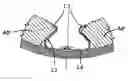
FIG. 1 shows a schematic perspective view of a permanent magnet field winding assembled to the cylinder head by spring clips according to the invention;
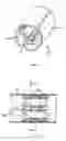
FIG. 2 shows a longitudinal sectional view according to line 2-2 of FIG. 3;
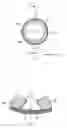
FIG. 3 represents a transversal section view according to line 3-3 of FIG. 2;
FIG. 4 is a detail view of a spring clip of FIG. 3;
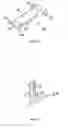
FIG. 5 shows a perspective view of a spring clip according to the invention;
FIG. 6 represents a partial sectional view of the extremity of the spring clip of FIG. 5 disposed on the cylinder head;
FIG. 7 is a view identical to FIG. 5 of a variation of embodiment;
FIG. 8 represents a partial section view of the extremity of the spring clip of FIG. 7 disposed on the cylinder head.
DESCRIPTION OF PREFERENTIAL EMBODIMENTS OF THE INVENTIONIn FIGS. 1 to 6, the field winding 10 is comprised of a tubular metallic cylinder head 11, and a plurality of permanent magnets PM in cylindrical segment forms, angularly distributed at regular intervals inside the cylinder head 11 in soft iron. The axial and radial support of the magnets PM in the cylinder head 11 is performed by means of elastic spring clips 12 inserted between the magnets PM. Each spring clip 12 is constructed from a metallic sheet, for example folded into a U and equipped with flaps 13 in the central area for the radial support of magnets PM. Locking fins 14, 15 are advantageously provided in the extremities of the spring clips 12 to assure the stable axial positioning of the permanent magnets PM. In a position of fixation, the curved core 16 of each spring clip 12 pushes against the internal wall of the cylinder head 11.
In a first phase, the set of permanent magnets PM and spring clips 12 is assembled in a specific tool. In a second phase, the tool is activated to tighten the assembly, and to position the assembly on a diameter that is slightly less than that of the inside of the cylindrical cylinder head 11. In a third phase, the cylinder head 11 just partially covers the assembly, and the tool is activated to loosen the assembly that, under the effect of the spring clips 12 that make a spring, lies flat on the inner diameter of the cylinder head 11. The field winding 10 is then removed from the tool to be placed in a clamp that terminates the axial insertion of the assembly into the cylinder head 11.
To prevent the spring clips 12 from engaging on the inner wall of the cylinder head 11, a first solution (FIGS. 5 and 6) consists of providing two bosses 17 in rounded forms, which are constructed onto the spring clips during the cutting operation. These bosses 17 are for example disposed between the two fins 14 at the extremity 20 penetrating first into the cylinder head, in such a way as to facilitate the sliding of the spring clips 12 in the inner wall of the cylinder head 11. Each spring clip 12 is set back from the inner wall of the cylinder head 11 by a small radial interval d. Contact between the end edge cutout of the spring clip 12 and the cylinder head 11 is therefore prevented.
In a second embodiment illustrated in FIGS. 7 and 8, the extremity 20 of the spring clip 12 of the side of the fins 14 is folded towards the center of the cylinder head 11 by forming a wedge-shaped tongue 18 designed to prevent contact of the live end edge against the inner surface of the cylinder head 11 during the course of insertion.
Claims
1. A device for fixing permanent magnets (PM) inside a cylinder head (11) of a field winding for an electrical engine, comprising elastic spring clips (12) disposed between the permanent magnets (PM) to maintain said magnets against the inner wall of the cylinder head (11), each spring clip (12) being made from a metallic sheet comprising a core (16) for holding two consecutive magnets (PM),
Characterized in that the extremity (20) of each spring clip (12), penetrating first into the cylinder head (11) during insertion of the permanent magnets (PM), comprises means to facilitate the axial sliding of the spring clips on the inner cylindrical wall of the cylinder head (11) by preventing all contact with an end edge of the extremity (20) of said spring clip against the inner wall of the cylinder head (11).
2. The fixation device according to claim 1, characterized in that the end edge of each spring clip (12) is set back from the cylinder head (11) by at least one boss (17) provided on the core (16).
3. The fixation device according to claim 2, characterized in that said boss (17) is situated set back from the end edge, and between two axial locking fins (14) of the magnets (PM).
4. The fixation device according to claim 1, characterized in that each spring clip (12) is set back from the cylinder head (11) by a wedge-shaped tongue (18).
5. The fixation device according to claim 1, characterized in that the core (16) of each spring clip (12) is curved by pushing against the inner wall of the cylinder head (11).
6. The fixation device according to claim 1, characterized in that the core (16) of each spring clip (12) is equipped with flaps (13) for holding two consecutive magnets (PM).
7. The fixation device according to claim 1, characterized in that the metallic sheet of each spring clip (12) is folded into a U.
8. An electrical engine of a starter of an automobile having a permanent magnet field winding, equipped with a fixation device by spring clip according to claim 1.
9. An electrical engine of a starter of an automobile having a permanent magnet field winding, equipped with a fixation device by spring clip according to claim 2.
10. An electrical engine of a starter of an automobile having a permanent magnet field winding, equipped with a fixation device by spring clip according to claim 3.
11. An electrical engine of a starter of an automobile having a permanent magnet field winding, equipped with a fixation device by spring clip according to claim 4.
12. An electrical engine of a starter of an automobile having a permanent magnet field winding, equipped with a fixation device by spring clip according to claim 5.
13. An electrical engine of a starter of an automobile having a permanent magnet field winding, equipped with a fixation device by spring clip according to claim 6.
14. An electrical engine of a starter of an automobile having a permanent magnet field winding, equipped with a fixation device by spring clip according to claim 7.
Images & Drawings included:

Sources:
- United States Patent and Trademark Office - verify current appl. status at the USPTO↗
Recent applications in this class:
- » 20220376594 2022-11-24
Motor - » 20220052590 2022-02-17
Movable permanent magnet stator electric motor - » 20190103795 2019-04-04
Permanent magnet rotor with enhanced demagnetization protection - » 20180375413 2018-12-27
Motor - » 20170331355 2017-11-16
Motor and rotary assembly thereof - » 20150349617 2015-12-03
Method and apparatus for determining a rotor position and rotation speed of an electrical machine - » 20130127279 2013-05-23
Repulsive force conversion drives and centrifugal force conversion - » 20120299405 2012-11-29
Electric motor - » 20120286611 2012-11-15
Motor - » 20120194023 2012-08-02
Permanent magnet motor
Recent applications for this Assignee:
- » 20230155447 2023-05-18
COVER FOR A ROTATING ELECTRIC MACHINE - » 20230146846 2023-05-11
Rotor for a rotating electric machine, and rotating electric machine - » 20230132537 2023-05-04
Undervoltage protection circuit for a DC/DC converter and method thereof - » 20230039095 2023-02-09
Device for determining the angular position of a rotor of a rotating electric machine - » 20230027557 2023-01-26
Stator comprising an interconnector - » 20230006494 2023-01-05
STATOR COMPRISING AN INTERCONNECTOR - » 20220407380 2022-12-22
Rotary electric machine provided with an end shield having an inner face configured for cooling - » 20220360130 2022-11-10
Electrical winding for a rotating electrical machine - » 20220352784 2022-11-03
Interconnections, sensors and control electronics mounted on a plastic bearing of an electric machine - » 20220263442 2022-08-18
Regulating module for a rotary electric machine