Handheld device with image sensor and printer
US20070126880A1
2007-06-07
11/672,878
2007-02-08
Abstract:
A handheld electronic device that has an image sensor for sensing an image in a first color space having three color components such that an image is sensed as an array of pixels, each having three color component intensities captured as analogue values. The device also has an analogue to digital converter for converting the analogue values to digital values, a memory facility for storing the digital values of the color components for each of the pixels in the array in a respective memory location, an address generator for generating an address that uniquely identifies the memory location of the digital values of the color components for each pixel, an inkjet printer for operation in a second color space and, a processor for manipulating the image by remapping at least some of the memory locations in the memory facility, and color converting the digital values of the color components into the second color space.
Interested in similar patents?
Get notified when new applications in this technology area are published.
Classification:
B41J2/01 » CPC main
Typewriters or selective printing mechanisms characterised by the printing or marking process for which they are designed characterised by bringing liquid or particles selectively into contact with a printing material Ink jet
B41J2/14 » CPC further
Typewriters or selective printing mechanisms characterised by the printing or marking process for which they are designed characterised by bringing liquid or particles selectively into contact with a printing material; Ink jet; Nozzles Structure thereof only for on-demand ink jet heads
B41J2/14314 » CPC further
Typewriters or selective printing mechanisms characterised by the printing or marking process for which they are designed characterised by bringing liquid or particles selectively into contact with a printing material; Ink jet; Nozzles; Structure thereof only for on-demand ink jet heads Structure of ink jet print heads with electrostatically actuated membrane
B41J2/14427 » CPC further
Typewriters or selective printing mechanisms characterised by the printing or marking process for which they are designed characterised by bringing liquid or particles selectively into contact with a printing material; Ink jet; Nozzles; Structure thereof only for on-demand ink jet heads Structure of ink jet print heads with thermal bend detached actuators
B41J2/16 » CPC further
Typewriters or selective printing mechanisms characterised by the printing or marking process for which they are designed characterised by bringing liquid or particles selectively into contact with a printing material; Ink jet; Nozzles Production of nozzles
B41J2/1601 » CPC further
Typewriters or selective printing mechanisms characterised by the printing or marking process for which they are designed characterised by bringing liquid or particles selectively into contact with a printing material; Ink jet; Nozzles; Production of nozzles Production of bubble jet print heads
B41J2/1623 » CPC further
Typewriters or selective printing mechanisms characterised by the printing or marking process for which they are designed characterised by bringing liquid or particles selectively into contact with a printing material; Ink jet; Nozzles; Production of nozzles manufacturing processes bonding and adhesion
B41J2/1626 » CPC further
Typewriters or selective printing mechanisms characterised by the printing or marking process for which they are designed characterised by bringing liquid or particles selectively into contact with a printing material; Ink jet; Nozzles; Production of nozzles manufacturing processes etching
B41J2/1631 » CPC further
Typewriters or selective printing mechanisms characterised by the printing or marking process for which they are designed characterised by bringing liquid or particles selectively into contact with a printing material; Ink jet; Nozzles; Production of nozzles manufacturing processes photolithography
B41J2/1632 » CPC further
Typewriters or selective printing mechanisms characterised by the printing or marking process for which they are designed characterised by bringing liquid or particles selectively into contact with a printing material; Ink jet; Nozzles; Production of nozzles manufacturing processes machining
B41J2/1635 » CPC further
Typewriters or selective printing mechanisms characterised by the printing or marking process for which they are designed characterised by bringing liquid or particles selectively into contact with a printing material; Ink jet; Nozzles; Production of nozzles manufacturing processes dividing the wafer into individual chips
B41J2/1637 » CPC further
Typewriters or selective printing mechanisms characterised by the printing or marking process for which they are designed characterised by bringing liquid or particles selectively into contact with a printing material; Ink jet; Nozzles; Production of nozzles manufacturing processes molding
B41J2/1648 » CPC further
Typewriters or selective printing mechanisms characterised by the printing or marking process for which they are designed characterised by bringing liquid or particles selectively into contact with a printing material; Ink jet; Nozzles; Production of nozzles Production of print heads with thermal bend detached actuators
B41J2/17503 » CPC further
Typewriters or selective printing mechanisms characterised by the printing or marking process for which they are designed characterised by bringing liquid or particles selectively into contact with a printing material; Ink jet characterised by ink handling; Ink supply systems ; Circuit parts therefor Ink cartridges
B41J2/17513 » CPC further
Typewriters or selective printing mechanisms characterised by the printing or marking process for which they are designed characterised by bringing liquid or particles selectively into contact with a printing material; Ink jet characterised by ink handling; Ink supply systems ; Circuit parts therefor; Ink cartridges Inner structure
B41J2/17596 » CPC further
Typewriters or selective printing mechanisms characterised by the printing or marking process for which they are designed characterised by bringing liquid or particles selectively into contact with a printing material; Ink jet characterised by ink handling; Ink supply systems ; Circuit parts therefor Ink pumps, ink valves
B41J3/00 » CPC further
Typewriters or selective printing or marking mechanisms, e.g. ink-jet printers, thermal printers characterised by the purpose for which they are constructed
B41J15/044 » CPC further
Devices or arrangements specially adapted for supporting or handling copy material in continuous form, e.g. webs; Supporting, feeding, or guiding devices; Mountings for web rolls or spindles Cassettes or cartridges containing continuous copy material, tape, for setting into printing devices
B41J29/02 » CPC further
Details of, or accessories for, typewriters or selective printing mechanisms not otherwise provided for Framework
B41J29/13 » CPC further
Details of, or accessories for, typewriters or selective printing mechanisms not otherwise provided for; Guards, shields or dust excluders Cases or covers
B82Y30/00 » CPC further
Nanotechnology for materials or surface science, e.g. nanocomposites
G03B17/02 » CPC further
Details of cameras or camera bodies; Accessories therefor Bodies
G03B17/24 » CPC further
Details of cameras or camera bodies; Accessories therefor with means for separately producing marks on the film, e.g. title, time of exposure
G03B17/48 » CPC further
Details of cameras or camera bodies; Accessories therefor adapted for combination with other photographic or optical apparatus
G03B27/02 » CPC further
Photographic printing apparatus Exposure apparatus for contact printing
G06F1/1626 » CPC further
Details not covered by groups - and; Constructional details or arrangements for portable computers with a single-body enclosure integrating a flat display, e.g. Personal Digital Assistants [PDAs]
G06F12/0866 » CPC further
Accessing, addressing or allocating within memory systems or architectures; Addressing or allocation; Relocation in hierarchically structured memory systems, e.g. virtual memory systems; Addressing of a memory level in which the access to the desired data or data block requires associative addressing means, e.g. caches for peripheral storage systems, e.g. disk cache
G06F21/79 » CPC further
Security arrangements for protecting computers, components thereof, programs or data against unauthorised activity; Protecting specific internal or peripheral components, in which the protection of a component leads to protection of the entire computer to assure secure storage of data in semiconductor storage media, e.g. directly-addressable memories
G06F21/86 » CPC further
Security arrangements for protecting computers, components thereof, programs or data against unauthorised activity; Protecting specific internal or peripheral components, in which the protection of a component leads to protection of the entire computer Secure or tamper-resistant housings
G06K1/121 » CPC further
Methods or arrangements for marking the record carrier in digital fashion otherwise than by punching by printing code marks
G06K7/10 » CPC further
Methods or arrangements for sensing record carriers, e.g. for reading patterns by electromagnetic radiation, e.g. optical sensing; by corpuscular radiation
G06K7/10722 » CPC further
Methods or arrangements for sensing record carriers, e.g. for reading patterns by electromagnetic radiation, e.g. optical sensing; by corpuscular radiation by scanning of the records by radiation in the optical part of the electromagnetic spectrum; Fixed beam scanning Photodetector array or CCD scanning
G06K7/14 » CPC further
Methods or arrangements for sensing record carriers, e.g. for reading patterns by electromagnetic radiation, e.g. optical sensing; by corpuscular radiation using light without selection of wavelength, e.g. sensing reflected white light
G06K7/1417 » CPC further
Methods or arrangements for sensing record carriers, e.g. for reading patterns by electromagnetic radiation, e.g. optical sensing; by corpuscular radiation using light without selection of wavelength, e.g. sensing reflected white light; Methods for optical code recognition the method being specifically adapted for the type of code 2D bar codes
G06K19/06 » CPC further
Record carriers for use with machines and with at least a part designed to carry digital markings characterised by the kind of the digital marking, e.g. shape, nature, code
G06K19/06037 » CPC further
Record carriers for use with machines and with at least a part designed to carry digital markings characterised by the kind of the digital marking, e.g. shape, nature, code with optically detectable marking multi-dimensional coding
G06K19/073 » CPC further
Record carriers for use with machines and with at least a part designed to carry digital markings characterised by the kind of the digital marking, e.g. shape, nature, code; Record carriers with conductive marks, printed circuits or semiconductor circuit elements, e.g. credit or identity cards also with resonating or responding marks without active components with integrated circuit chips Special arrangements for circuits, e.g. for protecting identification code in memory
G06Q20/3674 » CPC further
Payment architectures, schemes or protocols characterised by the use of specific devices or networks using electronic wallets or electronic money safes involving electronic purses or money safes involving authentication
G06Q20/382 » CPC further
Payment architectures, schemes or protocols; Payment protocols; Details thereof insuring higher security of transaction
G06Q20/3829 » CPC further
Payment architectures, schemes or protocols; Payment protocols; Details thereof insuring higher security of transaction involving key management
G06T1/20 » CPC further
General purpose image data processing Processor architectures; Processor configuration, e.g. pipelining
G06T3/0006 » CPC further
Geometric image transformation in the plane of the image Affine transformations
G07F7/08 » CPC further
Mechanisms actuated by objects other than coins to free or to actuate vending, hiring, coin or paper currency dispensing or refunding apparatus by coded identity card or credit card or other personal identification means
G07F7/086 » CPC further
Mechanisms actuated by objects other than coins to free or to actuate vending, hiring, coin or paper currency dispensing or refunding apparatus by coded identity card or credit card or other personal identification means by passive credit-cards adapted therefor, e.g. constructive particularities to avoid counterfeiting, e.g. by inclusion of a physical or chemical security-layer
G07F7/12 » CPC further
Mechanisms actuated by objects other than coins to free or to actuate vending, hiring, coin or paper currency dispensing or refunding apparatus by coded identity card or credit card or other personal identification means Card verification
G11B7/0033 » CPC further
Recording or reproducing by optical means, e.g. recording using a thermal beam of optical radiation , reproducing using an optical beam at lower power ; Record carriers therefor; Recording, reproducing or erasing systems characterised by the shape or form of the carrier with cards or other card-like flat carriers, e.g. flat sheets of optical film
G11B7/007 » CPC further
Recording or reproducing by optical means, e.g. recording using a thermal beam of optical radiation , reproducing using an optical beam at lower power ; Record carriers therefor Arrangement of the information on the record carrier, e.g. form of tracks, actual track shape, e.g. wobbled, or cross-section, e.g. v-shaped; Sequential information structures, e.g. sectoring or header formats within a track
G11C11/56 » CPC further
Digital stores characterised by the use of particular electric or magnetic storage elements; Storage elements therefor using storage elements with more than two stable states represented by steps, e.g. of voltage, current, phase, frequency
G11C16/22 » CPC further
Erasable programmable read-only memories electrically programmable; Auxiliary circuits, e.g. for writing into memory Safety or protection circuits preventing unauthorised or accidental access to memory cells
H01L23/576 » CPC further
Details of semiconductor or other solid state devices; Protection from inspection, reverse engineering or tampering using active circuits
H04L9/32 » CPC further
arrangements for secret or secure communications Cryptographic mechanisms or cryptographic ; Network security protocols including means for verifying the identity or authority of a user of the system or for message authentication, e.g. authorization, entity authentication, data integrity or data verification, non-repudiation, key authentication or verification of credentials
H04N1/00278 » CPC further
Scanning, transmission or reproduction of documents or the like, e.g. facsimile transmission; Details thereof; Connection or combination of a still picture apparatus with another apparatus, e.g. for storage, processing or transmission of still picture signals or of information associated with a still picture with a printing apparatus, e.g. a laser beam printer
H04N1/00326 » CPC further
Scanning, transmission or reproduction of documents or the like, e.g. facsimile transmission; Details thereof; Connection or combination of a still picture apparatus with another apparatus, e.g. for storage, processing or transmission of still picture signals or of information associated with a still picture with a data reading, recognizing or recording apparatus, e.g. with a bar-code apparatus
H04N1/00355 » CPC further
Scanning, transmission or reproduction of documents or the like, e.g. facsimile transmission; Details thereof; User-machine interface; Control console; Input means Mark-sheet input
H04N1/0044 » CPC further
Scanning, transmission or reproduction of documents or the like, e.g. facsimile transmission; Details thereof; User-machine interface; Control console; Output means; Display of information to the user, e.g. menus for image preview or review, e.g. to help the user position a sheet
H04N1/00965 » CPC further
Scanning, transmission or reproduction of documents or the like, e.g. facsimile transmission; Details thereof; Input arrangements for operating instructions or parameters, e.g. updating internal software using a plug-in memory module, e.g. memory card, memory stick
H04N1/00968 » CPC further
Scanning, transmission or reproduction of documents or the like, e.g. facsimile transmission; Details thereof; Input arrangements for operating instructions or parameters, e.g. updating internal software by scanning marks on a sheet
H04N1/2112 » CPC further
Scanning, transmission or reproduction of documents or the like, e.g. facsimile transmission; Details thereof; Intermediate information storage for one or a few pictures using still video cameras
H04N1/2154 » CPC further
Scanning, transmission or reproduction of documents or the like, e.g. facsimile transmission; Details thereof; Intermediate information storage for one or a few pictures using still video cameras the still video camera incorporating a hardcopy reproducing device, e.g. a printer
H04N1/2307 » CPC further
Scanning, transmission or reproduction of documents or the like, e.g. facsimile transmission; Details thereof; Reproducing arrangements Circuits or arrangements for the control thereof, e.g. using a programmed control device, according to a measured quantity
H04N1/32122 » CPC further
Scanning, transmission or reproduction of documents or the like, e.g. facsimile transmission; Details thereof; Circuits or arrangements for control or supervision between transmitter and receiver or between image input and image output device, e.g. between a still-image camera and its memory or between a still-image camera and a printer device; Display, printing, storage or transmission of additional information, e.g. ID code, date and time or title separate from the image data, e.g. in a different computer file in a separate device, e.g. in a memory or on a display separate from image data
H04N1/32133 » CPC further
Scanning, transmission or reproduction of documents or the like, e.g. facsimile transmission; Details thereof; Circuits or arrangements for control or supervision between transmitter and receiver or between image input and image output device, e.g. between a still-image camera and its memory or between a still-image camera and a printer device; Display, printing, storage or transmission of additional information, e.g. ID code, date and time or title attached to the image data, e.g. file header, transmitted message header, information on the same page or in the same computer file as the image on the same paper sheet, e.g. a facsimile page header
H04N5/2628 » CPC further
Details of television systems; Studio circuitry; Studio devices; Studio equipment ; Cameras comprising an electronic image sensor, e.g. digital cameras, video cameras, TV cameras, video cameras, camcorders, webcams, camera modules for embedding in other devices, e.g. mobile phones, computers or vehicles; Studio circuits, e.g. for mixing, switching-over, change of character of image, other special effects ; Cameras specially adapted for the electronic generation of special effects Alteration of picture size, shape, position or orientation, e.g. zooming, rotation, rolling, perspective, translation
H04N5/335 » CPC further
Details of television systems; Transforming light or analogous information into electric information using solid-state image sensors [SSIS]
B41J2/16585 » CPC further
Typewriters or selective printing mechanisms characterised by the printing or marking process for which they are designed characterised by bringing liquid or particles selectively into contact with a printing material; Ink jet; Nozzles; Preventing or detecting of nozzle clogging, e.g. cleaning, capping or moistening for nozzles for paper-width or non-reciprocating print heads
B41J2002/041 » CPC further
Typewriters or selective printing mechanisms characterised by the printing or marking process for which they are designed characterised by bringing liquid or particles selectively into contact with a printing material; Ink jet characterised by the jet generation process generating single droplets or particles on demand Electromagnetic transducer
B41J2002/14491 » CPC further
Typewriters or selective printing mechanisms characterised by the printing or marking process for which they are designed characterised by bringing liquid or particles selectively into contact with a printing material; Ink jet; Nozzles; Structure thereof only for on-demand ink jet heads Electrical connection
B41J2202/21 » CPC further
Embodiments of or processes related to ink-jet or thermal heads; Embodiments of or processes related to ink-jet heads Line printing
G06F2212/2022 » CPC further
Indexing scheme relating to accessing, addressing or allocation within memory systems or architectures; Employing a main memory using a specific memory technology; Non-volatile memory Flash memory
G06F2221/2129 » CPC further
Indexing scheme relating to security arrangements for protecting computers, components thereof, programs or data against unauthorised activity; Indexing scheme relating to and subgroups addressing additional information or applications relating to security arrangements for protecting computers, components thereof, programs or data against unauthorised activity Authenticate client device independently of the user
G09G2310/0281 » CPC further
Command of the display device; Addressing, scanning or driving the display screen or processing steps related thereto; Details of driving circuits Arrangement of scan or data electrode driver circuits at the periphery of a panel not inherent to a split matrix structure
H04N1/00127 » CPC further
Scanning, transmission or reproduction of documents or the like, e.g. facsimile transmission; Details thereof Connection or combination of a still picture apparatus with another apparatus, e.g. for storage, processing or transmission of still picture signals or of information associated with a still picture
H04N2101/00 » CPC further
Still video cameras
H04N2201/0008 » CPC further
Indexing scheme relating to scanning, transmission or reproduction of documents or the like, and to details thereof Connection or combination of a still picture apparatus with another apparatus
H01L2924/0002 » CPC further
Indexing scheme for arrangements or methods for connecting or disconnecting semiconductor or solid-state bodies as covered by; Technical content checked by a classifier Not covered by any one of groups , and
H04N5/225 » CPC further
Details of television systems; Studio circuitry; Studio devices; Studio equipment ; Cameras comprising an electronic image sensor, e.g. digital cameras, video cameras, TV cameras, video cameras, camcorders, webcams, camera modules for embedding in other devices, e.g. mobile phones, computers or vehicles Television cameras ; Cameras comprising an electronic image sensor, e.g. digital cameras, video cameras, camcorders, webcams, camera modules specially adapted for being embedded in other devices, e.g. mobile phones, computers or vehicles
H04N2201/0084 » CPC further
Indexing scheme relating to scanning, transmission or reproduction of documents or the like, and to details thereof; Types of the still picture apparatus Digital still camera
H04N2201/3222 » CPC further
Indexing scheme relating to scanning, transmission or reproduction of documents or the like, and to details thereof; Circuits or arrangements for control or supervision between transmitter and receiver or between image input and image output device, e.g. between a still-image camera and its memory or between a still-image camera and a printer device; Display, printing, storage or transmission of additional information, e.g. ID code, date and time or title of data relating to a job, e.g. communication, capture or filing of an image of processing required or performed, e.g. forwarding, urgent or confidential handling
H04N2201/3242 » CPC further
Indexing scheme relating to scanning, transmission or reproduction of documents or the like, and to details thereof; Circuits or arrangements for control or supervision between transmitter and receiver or between image input and image output device, e.g. between a still-image camera and its memory or between a still-image camera and a printer device; Display, printing, storage or transmission of additional information, e.g. ID code, date and time or title of data relating to an image, a page or a document of processing required or performed, e.g. for reproduction or before recording
H04N2201/3261 » CPC further
Indexing scheme relating to scanning, transmission or reproduction of documents or the like, and to details thereof; Circuits or arrangements for control or supervision between transmitter and receiver or between image input and image output device, e.g. between a still-image camera and its memory or between a still-image camera and a printer device; Display, printing, storage or transmission of additional information, e.g. ID code, date and time or title of multimedia information, e.g. a sound signal
H04N2201/3264 » CPC further
Indexing scheme relating to scanning, transmission or reproduction of documents or the like, and to details thereof; Circuits or arrangements for control or supervision between transmitter and receiver or between image input and image output device, e.g. between a still-image camera and its memory or between a still-image camera and a printer device; Display, printing, storage or transmission of additional information, e.g. ID code, date and time or title of multimedia information, e.g. a sound signal of sound signals
H04N2201/3269 » CPC further
Indexing scheme relating to scanning, transmission or reproduction of documents or the like, and to details thereof; Circuits or arrangements for control or supervision between transmitter and receiver or between image input and image output device, e.g. between a still-image camera and its memory or between a still-image camera and a printer device; Display, printing, storage or transmission of additional information, e.g. ID code, date and time or title of machine readable codes or marks, e.g. bar codes or glyphs
H04N2201/3276 » CPC further
Indexing scheme relating to scanning, transmission or reproduction of documents or the like, and to details thereof; Circuits or arrangements for control or supervision between transmitter and receiver or between image input and image output device, e.g. between a still-image camera and its memory or between a still-image camera and a printer device; Display, printing, storage or transmission of additional information, e.g. ID code, date and time or title; Storage or retrieval of prestored additional information of a customised additional information profile, e.g. a profile specific to a user ID
H04N2201/328 » CPC further
Indexing scheme relating to scanning, transmission or reproduction of documents or the like, and to details thereof; Circuits or arrangements for control or supervision between transmitter and receiver or between image input and image output device, e.g. between a still-image camera and its memory or between a still-image camera and a printer device; Display, printing, storage or transmission of additional information, e.g. ID code, date and time or title Processing of the additional information
H05K1/14 » CPC further
Printed circuits; Details Structural association of two or more printed circuits
H05K1/14 » CPC further
Printed circuits; Details Structural association of two or more printed circuits
H05K1/189 » CPC further
Printed circuits; Printed circuits structurally associated with non-printed electric components characterised by the use of a flexible or folded printed circuit
H05K1/189 » CPC further
Printed circuits; Printed circuits structurally associated with non-printed electric components characterised by the use of a flexible or folded printed circuit
Y02D10/00 » CPC further
Energy efficient computing, e.g. low power processors, power management or thermal management
Y02D10/00 » CPC further
Energy efficient computing, e.g. low power processors, power management or thermal management
Y10S977/839 » CPC further
Nanotechnology Mathematical algorithms, e.g. computer software, specifically adapted for modeling configurations or properties of nanostructure
Y10S977/843 » CPC further
Nanotechnology; Manufacture, treatment, or detection of nanostructure for carbon nanotubes or fullerenes Gas phase catalytic growth, i.e. chemical vapor deposition
Y10S977/901 » CPC further
Nanotechnology; Manufacture, treatment, or detection of nanostructure having step or means utilizing electromagnetic property, e.g. optical, x-ray, electron beamm
Y10S977/94 » CPC further
Nanotechnology; Specified use of nanostructure for electronic or optoelectronic application in a logic circuit
H01L2924/00 » CPC further
Indexing scheme for arrangements or methods for connecting or disconnecting semiconductor or solid-state bodies as covered by
Description
CROSS REFERENCE TO RELATED APPLICATIONThe present application is a continuation of U.S. application Ser. No. 09/113,094 filed on Jul. 10, 1998 all of which are herein incorporated by reference.
FIELD OF THE INVENTIONThe present invention relates substantially to the concept of a disposable camera having instant printing capabilities and in particular, discloses a method of color correction in a digital camera.
BACKGROUND OF THE INVENTIONRecently, the concept of a “single use” disposable camera has become an increasingly popular consumer item. Disposable camera systems presently on the market normally include an internal film roll and a simplified gearing mechanism for traversing the film roll across an imaging system including a shutter and lensing system. The user, after utilising a single film roll returns the camera system to a film development centre for processing. The film roll is taken out of the camera system and processed and the prints returned to the user. The camera system is then able to be re-manufactured through the insertion of a new film roll into the camera system, the replacement of any worn or wearable parts and the re-packaging of the camera system in accordance with requirements. In this way, the concept of a single use “disposable” camera is provided to the consumer.
Recently, a camera system has been proposed by the present applicant which provides for a handheld camera device having an internal printhead, image sensor and processing means such that images sense by the image sensing means, are processed by the processing means and adapted to be instantly printed out by the printing means on demand. The proposed camera system further discloses a system of internal “print rolls” carrying print media such as film on to which images are to be printed in addition to ink for supplying to the printing means for the printing process. The print roll is further disclosed to be detachable and replaceable within the camera system.
Unfortunately, such a system is likely to only be constructed at a substantial cost and it would be desirable to provide for a more inexpensive form of instant camera system which maintains a substantial number of the quality aspects of the aforementioned arrangement.
It would be advantageous to provide for a camera system having an effective color correction or gamma remapping capability.
SUMMARY OF THE INVENTIONIn a first aspect the present invention provides a method of colour correcting a sensed image before printing by a hand held camera system, said camera system including:
an image sensor device for sensing an image;
a processing means for processing said sensed image; and
a printing system including a printhead for printing out said sensed image; wherein the method of colour correcting a sensed image before printing comprises:
-
- utilizing said image sensor device to sense a first image;
- processing said first image to determine colour characteristics of said first image;
- utilizing said image sensor device to sense a second image, in rapid succession to said first image;
- applying colour correction to said second image based on the determined colour characteristics of said first image; and
- printing out said second image by said printhead.
Optionally said second image is sensed within 1 second of said first image.
Optionally said processing step includes examining the intensity characteristics of said first image.
Optionally said processing step includes determining a maximum and minimum intensity of said first image and utilizing said intensities to rescale the intensities of said second image.
Notwithstanding any other forms which may fall within the scope of the present invention, preferred forms of the invention will now be described, by way of example only, with reference to the accompanying drawings in which:
FIG. 1 illustrates a front perspective view of the assembled camera of the preferred embodiment;
FIG. 2 illustrates a rear perspective view, partly exploded, of the preferred embodiment;
FIG. 3 is a perspective view of the chassis of the preferred embodiment;
FIG. 4 is a perspective view of the chassis illustrating mounting of electric motors;
FIG. 5 is an exploded perspective view of the ink supply mechanism of the preferred embodiment;
FIG. 6 is rear perspective of the assembled form of the ink supply mechanism of the preferred embodiment;
FIG. 7 is a front perspective view of the assembled form of the ink supply mechanism of the preferred embodiment;
FIG. 8 is an exploded perspective view of the platten unit of the preferred embodiment;
FIG. 9 is a perspective view of the assembled form of the platten unit;
FIG. 10 is also a perspective view of the assembled form of the platten unit;
FIG. 11 is an exploded perspective view of the printhead recapping mechanism of the preferred embodiment;
FIG. 12 is a close up exploded perspective view of the recapping mechanism of the preferred embodiment;
FIG. 13 is an exploded perspective view of the ink supply cartridge of the preferred embodiment;
FIG. 14 is a close up perspective view, partly in section of the internal portions of the ink supply cartridge in an assembled form;
FIG. 15 is a schematic block diagram of one form of chip layer of the image capture and processing chip of the preferred embodiment;
FIG. 16 is an exploded perspective view illustrating the assembly process of the preferred embodiment;
FIG. 17 illustrates a front exploded perspective view of the assembly process of the preferred embodiment;
FIG. 18 illustrates a perspective view of the assembly process of the preferred embodiment;
FIG. 19 illustrates a perspective view of the assembly process of the preferred embodiment;
FIG. 20 is a perspective view illustrating the insertion of the platten unit in the preferred embodiment;
FIG. 21 illustrates the interconnection of the electrical components of the preferred embodiment;
FIG. 22 illustrates the process of assembling the preferred embodiment; and
FIG. 23 is a perspective view further illustrating the assembly process of the preferred embodiment.
DESCRIPTION OF PREFERRED AND OTHER EMBODIMENTSTurning to FIG. 1 and FIG. 2 there an illustrated perspective views of an assembled camera constructed in accordance with the preferred embodiment with FIG. 1 showing a front perspective view and FIG. 2 showing a rear perspective view. The camera 1 includes a paper or plastic film jacket 2 which can include simplified instructions 3 for the operation of the camera system 1. The camera system 1 includes a first “take” button 4 which is depressed to capture an image. The captured image is output via output slot 6. A further copy of the image can be obtained through depressing a second “printer copy” button 7 whilst an LED light 5 is illuminated. The camera system also provides the usual view finder 8 in addition to a CCD image capture/lensing system 9.
The camera system 1 provides for a standard number of output prints after which the camera system 1 ceases to function. A prints left indicator slot 10 is provided to indicate the number of remaining prints. A refund scheme at the point of purchase is assumed to be operational for the return of used camera systems for recycling.
Turning now to FIG. 3, the assembly of the camera system is based around an internal chassis 12 which can be a plastic injection molded part. A pair of paper pinch rollers 28, 29 utilized for decurling are snap fitted into corresponding frame holes eg. 26, 27.
As shown in FIG. 4, the chassis 12 includes a series of mutually opposed prongs eg. 13, 14 into which is snap fitted a series of electric motors 16, 17. The electric motors 16, 17 can be entirely standard with the motor 16 being of a stepper motor type. The motors 16, 17 include cogs 19, 20 for driving a series of gear wheels. A first set of gear wheels is provided for controlling a paper cutter mechanism and a second set is provided for controlling print roll movement.
Turning next to FIGS. 5 to 7, there is illustrated an ink supply mechanism 40 utilized in the camera system. FIG. 5 illustrates a rear exploded perspective view, FIG. 6 illustrates a assembled perspective view and FIG. 7 illustrates a front assembled view. The ink supply mechanism 40 is based around an ink supply cartridge 42 which contains printer ink and a printhead mechanism for printing out pictures on demand. The ink supply cartridge 42 includes a side aluminium strip 43 which is provided as a shear strip to assist in cutting images from a paper roll.
A dial mechanism 44 is provided for indicating the number of “prints left”. The dial mechanism 44 is snap fitted through a corresponding mating portion 46 so as to be freely rotatable.
As shown in FIG. 6, the mechanism 40 includes a flexible PCB strip 47 which interconnects with the printhead and provides for control of the printhead. The interconnection between the Flex PCB strip and an image sensor and printhead chip can be via Tape Automated Bonding (TAB) strips 51, 58. A moulded aspherical lens and aperture shim 50 (FIG. 5) is also provided for imaging an image onto the surface of the image sensor chip normally located within cavity 53 and a light box module or hood 52 is provided for snap fitting over the cavity 53 so as to provide for proper light control. A series of decoupling capacitors eg. 34 can also be provided. Further a plug 45 (FIG. 7) is provided for re-plugging ink holes after refilling. A series of guide prongs eg. 55-57 are further provided for guiding the flexible PCB strip 47.
The ink supply mechanism 40 interacts with a platten unit 60 which guides print media under a printhead located in the ink supply mechanism. FIG. 8 shows an exploded view of the platten unit 60, while FIGS. 9 and 10 show assembled views of the platten unit. The platten unit 60 includes a first pinch roller 61 which is snap fitted to one side of a platten base 62. Attached to a second side of the platten base 62 is a cutting mechanism 63 which traverses the platen unit 60 by means of a rod 64 having a screw thread which is rotated by means of cogged wheel 65 which is also fitted to the platen base 62. The screw threaded rod 64 mounts a block 67 which includes a cutting wheel 68 fastened via a fastener 69. Also mounted to the block 67 is a counter actuator which includes a pawl 71. The pawl 71 acts to rotate the dial mechanism 44 of FIG. 6 upon the return traversal of the cutting wheel. As shown previously in FIG. 6, the dial mechanism 44 includes a cogged surface which interacts with pawl 71, thereby maintaining a count of the number of photographs by means of numbers embossed on the surface of dial mechanism 44. The cutting mechanism 63 is inserted into the platten base 62 by means of a snap fit via clips 74.
The platten unit 60 includes an internal recapping mechanism 80 for recapping the printhead when not in use. The recapping mechanism 80 includes a sponge portion 81 and is operated via a solenoid coil so as to provide for recapping of the printhead. In the preferred embodiment, there is provided an inexpensive form of printhead re-capping mechanism provided for incorporation into a handheld camera system so as to provide for printhead re-capping of an inkjet printhead.
FIG. 11 illustrates an exploded view of the recapping mechanism whilst FIG. 12 illustrates a close up of the end portion thereof. The re-capping mechanism 80 is structured around a solenoid including a 16 turn coil 75 which can comprise insulated wire. The coil 75 is turned around a first stationery solenoid arm 76 which is mounted on a bottom surface of the platen base 62 (FIG. 8) and includes a post portion 77 to magnify effectiveness of operation. The arm 76 can comprise a ferrous material.
A second moveable arm 78 of the solenoid actuator is also provided. The arm 78 is moveable and also is made of ferrous material. Mounted on the arm is a sponge portion surrounded by an elastomer strip 79. The elastomer strip 79 is of a generally arcuate cross-section and acts as a leaf spring against the surface of the printhead ink supply cartridge 42 (FIG. 5) so as to provide for a seal against the surface of the printhead ink supply cartridge 42. In the quiescent position elastomer spring units 87, 88 act to resiliently deform the elastomer seal 79 against the surface of the ink supply unit 42.
When it is desired to operate the printhead unit, upon the insertion of paper, the solenoid coil 75 is activated so as to cause the arm 78 to move down to be adjacent to the end plate 76. The arm 78 is held against end plate 76 while the printhead is printing by means of a small “keeper current” in coil 75. Simulation results indicate that the keeper current can be significantly less than the actuation current. Subsequently, after photo printing, the paper is guillotined by the cutting mechanism 63 of FIG. 8 acting against Aluminium Strip 43, and rewound so as to clear the area of the re-capping mechanism 80. Subsequently, the current is turned off and springs 87, 88 return the arm 78 so that the elastomer seal is again resting against the printhead ink supply cartridge.
It can be seen that the preferred embodiment provides for a simple and inexpensive means of re-capping a printhead through the utilisation of a solenoid type device having a long rectangular form. Further, the preferred embodiment utilises minimal power in that currents are only required whilst the device is operational and additionally, only a low keeper current is required whilst the printhead is printing.
Turning next to FIGS. 13 and 14, FIG. 13 illustrates an exploded perspective of the ink supply cartridge 42 whilst FIG. 14 illustrates a close up sectional view of a bottom of the ink supply cartridge with the printhead unit in place. The ink supply cartridge 42 is based around a pagewidth printhead 102 which comprises a long slither of silicon having a series of holes etched on the back surface for the supply of ink to a front surface of the silicon wafer for subsequent ejection via a micro electro mechanical system. The form of ejection can be many different forms such as those set out in the tables below.
Of course, many other inkjet technologies, as referred to the attached tables below, can also be utilised when constructing a printhead unit 102. The fundamental requirement of the ink supply cartridge 42 is the supply of ink to a series of colour channels etched through the back surface of the printhead 102. In the description of the preferred embodiment, it is assumed that a three colour printing process is to be utilised so as to provide full colour picture output. Hence, the print supply unit includes three ink supply reservoirs being a cyan reservoir 104, a magenta reservoir 105 and a yellow reservoir 106. Each of these reservoirs is required to store ink and includes a corresponding sponge type material 107-109 which assists in stabilising ink within the corresponding ink channel and inhibiting the ink from sloshing back and forth when the printhead is utilised in a handheld camera system. The reservoirs 104, 105, 106 are formed through the mating of first exterior plastic piece 110 and a second base piece 111.
At a first end 118 of the base piece 111 a series of air inlets 113-115 are provided. Each air inlet leads to a corresponding winding channel which is hydrophobically treated so as to act as an ink repellent and therefore repel any ink that may flow along the air inlet channel. The air inlet channel further takes a convoluted path further assisting in resisting any ink flow out of the chambers 104-106. An adhesive tape portion 117 is provided for sealing the channels within end portion 118.
At the top end, there is included a series of refill holes (not shown) for refilling corresponding ink supply chambers 104, 105, 106. A plug 121 is provided for sealing the refill holes.
Turning now to FIG. 14, there is illustrated a close up perspective view, partly in section through the ink supply cartridge 42 of FIG. 13 when formed as a unit. The ink supply cartridge includes the three colour ink reservoirs 104, 105, 106 which supply ink to different portions of the back surface of printhead 102 which includes a series of apertures 128 defined therein for carriage of the ink to the front surface.
The ink supply cartridge 42 includes two guide walls 124, 125 which separate the various ink chambers and are tapered into an end portion abutting the surface of the printhead 102. The guide walls 124, 125 are further mechanically supported by block portions eg. 126 which are placed at regular intervals along the length of the ink supply unit. The block portions 126 leave space at portions close to the back of printhead 102 for the flow of ink around the back surface thereof.
The ink supply unit is preferably formed from a multi-part plastic injection mold and the mold pieces eg. 110, 111 (FIG. 13) snap together around the sponge pieces 107, 109. Subsequently, a syringe type device can be inserted in the ink refill holes and the ink reservoirs filled with ink with the air flowing out of the air outlets 113-115. Subsequently, the adhesive tape portion 117 and plug 121 are attached and the printhead tested for operation capabilities. Subsequently, the ink supply cartridge 42 can be readily removed for refilling by means of removing the ink supply cartridge, performing a washing cycle, and then utilising the holes for the insertion of a refill syringe filled with ink for refilling the ink chamber before returning the ink supply cartridge 42 to a camera.
Turning now to FIG. 15, there is shown an example layout of the Image Capture and Processing Chip (ICP) 48.
The Image Capture and Processing Chip 48 provides most of the electronic functionality of the camera with the exception of the printhead chip. The chip 48 is a highly integrated system. It combines CMOS image sensing, analog to digital conversion, digital image processing, DRAM storage, ROM, and miscellaneous control functions in a single chip.
The chip is estimated to be around 32 mm2 using a leading edge 0.18 micron CMOS/DRAM/APS process. The chip size and cost can scale somewhat with Moore's law, but is dominated by a CMOS active pixel sensor array 201, so scaling is limited as the sensor pixels approach the diffraction limit.
The ICP 48 includes CMOS logic, a CMOS image sensor, DRAM, and analog circuitry. A very small amount of flash memory or other non-volatile memory is also preferably included for protection against reverse engineering.
Alternatively, the ICP can readily be divided into two chips: one for the CMOS imaging array, and the other for the remaining circuitry. The cost of this two chip solution should not be significantly different than the single chip ICP, as the extra cost of packaging and bond-pad area is somewhat cancelled by the reduced total wafer area requiring the color filter fabrication steps.
The ICP preferably contains the following functions:
| Function |
| 1.5 megapixel image sensor | |
| Analog Signal Processors | |
| Image sensor column decoders | |
| Image sensor row decoders | |
| Analogue to Digital Conversion (ADC) | |
| Column ADC's | |
| Auto exposure | |
| 12 Mbits of DRAM | |
| DRAM Address Generator | |
| Color interpolator | |
| Convolver | |
| Color ALU | |
| Halftone matrix ROM | |
| Digital halftoning | |
| printhead interface | |
| 8 bit CPU core | |
| Program ROM | |
| Flash memory | |
| Scratchpad SRAM | |
| Parallel interface (8 bit) | |
| Motor drive transistors (5) | |
| Clock PLL | |
| JTAG test interface | |
| Test circuits | |
| Busses | |
| Bond pads | |
The CPU, DRAM, Image sensor, ROM, Flash memory, Parallel interface, JTAG interface and ADC can be vendor supplied cores. The ICP is intended to run on 1.5V to minimize power consumption and allow convenient operation from two AA type battery cells.
FIG. 15 illustrates a layout of the ICP 48. The ICP 48 is dominated by the imaging array 201, which consumes around 80% of the chip area. The imaging array is a CMOS 4 transistor active pixel design with a resolution of 1,500×1,000. The array can be divided into the conventional configuration, with two green pixels, one red pixel, and one blue pixel in each pixel group. There are 750×500 pixel groups in the imaging array.
The latest advances in the field of image sensing and CMOS image sensing in particular can be found in the October, 1997 issue of IEEE Transactions on Electron Devices and, in particular, pages 1689 to 1968. Further, a specific implementation similar to that disclosed in the present application is disclosed in Wong et. al, “CMOS Active Pixel Image Sensors Fabricated Using a 1.8V, 0.25 μm CMOS Technology”, IEDM 1996, page 915
The imaging array uses a 4 transistor active pixel design of a standard configuration. To minimize chip area and therefore cost, the image sensor pixels should be as small as feasible with the technology available. With a four transistor cell, the typical pixel size scales as 20 times the lithographic feature size. This allows a minimum pixel area of around 3.6 μm×3.6 μm. However, the photosite must be substantially above the diffraction limit of the lens. It is also advantageous to have a square photosite, to maximize the margin over the diffraction limit in both horizontal and vertical directions. In this case, the photosite can be specified as 2.5 μm×2.5 μm. The photosite can be a photogate, pinned photodiode, charge modulation device, or other sensor.
The four transistors are packed as an ‘L’ shape, rather than a rectangular region, to allow both the pixel and the photosite to be square. This reduces the transistor packing density slightly, increasing pixel size. However, the advantage in avoiding the diffraction limit is greater than the small decrease in packing density.
The transistors also have a gate length which is longer than the minimum for the process technology. These have been increased from a drawn length of 0.18 micron to a drawn length of 0.36 micron. This is to improve the transistor matching by making the variations in gate length represent a smaller proportion of the total gate length.
The extra gate length, and the ‘L’ shaped packing, mean that the transistors use more area than the minimum for the technology. Normally, around 8 μm2 would be required for rectangular packing. Preferably, 9.75 μm2 has been allowed for the transistors.
The total area for each pixel is 16 μm2, resulting from a pixel size of 4 μm×4 μm. With a resolution of 1,500×1,000, the area of the imaging array 101 is 6,000 μm×4,000 μm, or 24 mm2.
The presence of a color image sensor on the chip affects the process required in two major ways:
-
- The CMOS fabrication process should be optimized to minimize dark current
Color filters are required. These can be fabricated using dyed photosensitive polyimides, resulting in an added process complexity of three spin coatings, three photolithographic steps, three development steps, and three hardbakes.
There are 15,000 analog signal processors (ASPs) 205, one for each of the columns of the sensor. The ASPs amplify the signal, provide a dark current reference, sample and hold the signal, and suppress the fixed pattern noise (FPN).
There are 375 analog to digital converters 206, one for each four columns of the sensor array. These may be delta-sigma or successive approximation type ADC's. A row of low column ADC's are used to reduce the conversion speed required, and the amount of analog signal degradation incurred before the signal is converted to digital. This also eliminates the hot spot (affecting local dark current) and the substrate coupled noise that would occur if a single high speed ADC was used. Each ADC also has two four bit DAC's which trim the offset and scale of the ADC to further reduce FPN variations between columns. These DAC's are controlled by data stored in flash memory during chip testing.
The column select logic 204 is a 1:1500 decoder which enables the appropriate digital output of the ADCs onto the output bus. As each ADC is shared by four columns, the least significant two bits of the row select control 4 input analog multiplexers.
A row decoder 207 is a 1:1000 decoder which enables the appropriate row of the active pixel sensor array. This selects which of the 1000 rows of the imaging array is connected to analog signal processors. As the rows are always accessed in sequence, the row select logic can be implemented as a shift register.
An auto exposure system 208 adjusts the reference voltage of the ADC 205 in response to the maximum intensity sensed during the previous frame period. Data from the green pixels is passed through a digital peak detector. The peak value of the image frame period before capture (the reference frame) is provided to a digital to analogue converter (DAC), which generates the global reference voltage for the column ADCs. The peak detector is reset at the beginning of the reference frame. The minimum and maximum values of the three RGB color components are also collected for color correction.
The second largest section of the chip is consumed by a DRAM 210 used to hold the image. To store the 1,500×1,000 image from the sensor without compression, 1.5 Mbytes of DRAM 210 are required. This equals 12 Mbits, or slightly less than 5% of a 256 Mbit DRAM. The DRAM technology assumed is of the 256 Mbit generation implemented using 0.18 μm CMOS.
Using a standard 8F cell, the area taken by the memory array is 3.11 mm2. When row decoders, column sensors, redundancy, and other factors are taken into account, the DRAM requires around 4 mm2.
This DRAM 210 can be mostly eliminated if analog storage of the image signal can be accurately maintained in the CMOS imaging array for the two seconds required to print the photo. However, digital storage of the image is preferable as it is maintained without degradation, is insensitive to noise, and allows copies of the photo to be printed considerably later.
A DRAM address generator 211 provides the write and read addresses to the DRAM 210. Under normal operation, the write address is determined by the order of the data read from the CMOS image sensor 201. This will typically be a simple raster format. However, the data can be read from the sensor 201 in any order, if matching write addresses to the DRAM are generated. The read order from the DRAM 210 will normally simply match the requirements of a color interpolator and the printhead. As the cyan, magenta, and yellow rows of the printhead are necessarily offset by a few pixels to allow space for nozzle actuators, the colors are not read from the DRAM simultaneously. However, there is plenty of time to read all of the data from the DRAM many times during the printing process. This capability is used to eliminate the need for FIFOs in the printhead interface, thereby saving chip area. All three RGB image components can be read from the DRAM each time color data is required. This allows a color space converter to provide a more sophisticated conversion than a simple linear RGB to CMY conversion.
Also, to allow two dimensional filtering of the image data without requiring line buffers, data is re-read from the DRAM array.
The address generator may also implement image effects in certain models of camera. For example, passport photos are generated by a manipulation of the read addresses to the DRAM. Also, image framing effects (where the central image is reduced), image warps, and kaleidoscopic effects can all be generated by manipulating the read addresses of the DRAM.
While the address generator 211 may be implemented with substantial complexity if effects are built into the standard chip, the chip area required for the address generator is small, as it consists only of address counters and a moderate amount of random logic.
A color interpolator 214 converts the interleaved pattern of red, 2× green, and blue pixels into RGB pixels. It consists of three 8 bit adders and associated registers. The divisions are by either 2 (for green) or 4 (for red and blue) so they can be implemented as fixed shifts in the output connections of the adders.
A convolver 215 is provided as a sharpening filter which applies a small convolution kernel (5×5) to the red, green, and blue planes of the image. The convolution kernel for the green plane is different from that of the red and blue planes, as green has twice as many samples. The sharpening filter has five functions:
-
- To improve the color interpolation from the linear interpolation provided by the color interpolator, to a close approximation of a sync interpolation.
- To compensate for the image ‘softening’ which occurs during digitization.
- To adjust the image sharpness to match average consumer preferences, which are typically for the image to be slightly sharper than reality. As the single use camera is intended as a consumer product, and not a professional photographic products, the processing can match the most popular settings, rather than the most accurate.
- To suppress the sharpening of high frequency (individual pixel) noise. The function is similar to the ‘unsharp mask’ process.
- To antialias Image Warping.
These functions are all combined into a single convolution matrix. As the pixel rate is low (less than 1 Mpixel per second) the total number of multiplies required for the three color channels is 56 million multiplies per second. This can be provided by a single multiplier. Fifty bytes of coefficient ROM are also required.
A color ALU 113 combines the functions of color compensation and color space conversion into the one matrix multiplication, which is applied to every pixel of the frame. As with sharpening, the color correction should match the most popular settings, rather than the most accurate.
A color compensation circuit of the color ALU provides compensation for the lighting of the photo. The vast majority of photographs are substantially improved by a simple color compensation, which independently normalizes the contrast and brightness of the three color components.
A color look-up table (CLUT) 212 is provided for each color component. These are three separate 256×8 SRAMs, requiring a total of 6,144 bits. The CLUTs are used as part of the color correction process. They are also used for color special effects, such as stochastically selected “wild color” effects.
A color space conversion system of the color ALU converts from the RGB color space of the image sensor to the CMY color space of the printer. The simplest conversion is a l's complement of the RGB data. However, this simple conversion assumes perfect linearity of both color spaces, and perfect dye spectra for both the color filters of the image sensor, and the ink dyes. At the other extreme is a tri-linear interpolation of a sampled three dimensional arbitrary transform table. This can effectively match any non-linearity or differences in either color space. Such a system is usually necessary to obtain good color space conversion when the print engine is a color electrophotographic.
However, since the non-linearity of a halftoned ink jet output is very small, a simpler system can be used. A simple matrix multiply can provide excellent results. This requires nine multiplies and six additions per contone pixel. However, since the contone pixel rate is low (less than 1 Mpixel/sec) these operations can share a single multiplier and adder. The multiplier and adder are used in a color ALU which is shared with the color compensation function.
Digital halftoning can be performed as a dispersed dot ordered dither using a stochastic optimized dither cell. A halftone matrix ROM 216 is provided for storing dither cell coefficients. A dither cell size of 32×32 is adequate to ensure that the cell repeat cycle is not visible. The three colors—cyan, magenta, and yellow—are all dithered using the same cell, to ensure maximum co-positioning of the ink dots. This minimizes ‘muddying’ of the mid-tones which results from bleed of dyes from one dot to adjacent dots while still wet. The total ROM size required is 1 KByte, as the one ROM is shared by the halftoning units for each of the three colors.
The digital halftoning used is dispersed dot ordered dither with stochastic optimized dither matrix. While dithering does not produce an image quite as ‘sharp’ as error diffusion, it does produce a more accurate image with fewer artifacts. The image sharpening produced by error diffusion is artificial, and less controllable and accurate than ‘unsharp mask’ filtering performed in the contone domain. The high print resolution (1,600 dpi×1,600 dpi) results in excellent quality when using a well formed stochastic dither matrix.
Digital halftoning is performed by a digital halftoning unit 217 using a simple comparison between the contone information from the DRAM 210 and the contents of the dither matrix 216. During the halftone process, the resolution of the image is changed from the 250 dpi of the captured contone image to the 1,600 dpi of the printed image. Each contone pixel is converted to an average of 40.96 halftone dots.
The ICP incorporates a 16 bit microcontroller CPU core 219 to run the miscellaneous camera functions, such as reading the buttons, controlling the motor and solenoids, setting up the hardware, and authenticating the refill station. The processing power required by the CPU is very modest, and a wide variety of processor cores can be used. As the entire CPU program is run from a small ROM 220. Program compatibility between camera versions is not important, as no external programs are run. A 2 Mbit (256 Kbyte) program and data ROM 220 is included on chip. Most of this ROM space is allocated to data for outline graphics and fonts for specialty cameras. The program requirements are minor. The single most complex task is the encrypted authentication of the refill station. The ROM requires a single transistor per bit.
A Flash memory 221 may be used to store a 128 bit authentication code. This provides higher security than storage of the authentication code in ROM, as reverse engineering can be made essentially impossible. The Flash memory is completely covered by third level metal, making the data impossible to extract using scanning probe microscopes or electron beams. The authentication code is stored in the chip when manufactured. At least two other Flash bits are required for the authentication process: a bit which locks out reprogramming of the authentication code, and a bit which indicates that the camera has been refilled by an authenticated refill station. The flash memory can also be used to store FPN correction data for the imaging array. Additionally, a phase locked loop rescaling parameter is stored and provided for scaling the clocking cycle to an appropriate correct time. The clock frequency does not require crystal accuracy since no date functions are provided. To eliminate the cost of a crystal, an on chip oscillator with a phase locked loop 224 is used. As the frequency of an on-chip oscillator is highly variable from chip to chip, the frequency ratio of the oscillator to the PLL is digitally trimmed during initial testing. The value is stored in Flash memory 221. This allows the clock PLL to control the ink-jet heater pulse width with sufficient accuracy.
A scratchpad SRAM is a small static RAM 222 with a 6T cell. The scratchpad provides temporary memory for the 16 bit CPU. 1024 bytes is adequate.
A printhead interface 223 formats the data correctly for the printhead. The printhead interface also provides all of the timing signals required by the printhead. These timing signals may vary depending upon temperature, the number of dots printed simultaneously, the print medium in the print roll, and the dye density of the ink in the print roll.
The following is a table of external connections to the printhead interface:
| Connection | Function | Pins |
| DataBits[0-7] | Independent serial data to the eight | 8 |
| segments of the printhead | ||
| BitClock | Main data clock for the printhead | 1 |
| ColorEnable[0-2] | Independent enable signals for the CMY | 3 |
| actuators, allowing different pulse times | ||
| for each color. | ||
| BankEnable[0-1] | Allows either simultaneous or interleaved | 2 |
| actuation of two banks of nozzles. This | ||
| allows two different print speed/power | ||
| consumption tradeoffs | ||
| NozzleSelect[0-4] | Selects one of 32 banks of nozzles for | 5 |
| simultaneous actuation | ||
| ParallelXferClock | Loads the parallel transfer register with | 1 |
| the data from the shift registers | ||
| Total | 20 | |
The printhead utilized is composed of eight identical segments, each 1.25 cm long. There is no connection between the segments on the printhead chip. Any connections required are made in the external TAB bonding film, which is double sided. The division into eight identical segments is to simplify lithography using wafer steppers. The segment width of 1.25 cm fits easily into a stepper field. As the printhead chip is long and narrow (10 cm×0.3 mm), the stepper field contains a single segment of 32 printhead chips. The stepper field is therefore 1.25 cm×1.6 cm. An average of four complete printheads are patterned in each wafer step.
A single BitClock output line connects to all 8 segments on the printhead. The 8 DataBits lines lead one to each segment, and are clocked in to the 8 segments on the printhead simultaneously (on a BitClock pulse). For example, dot 0 is transferred to segment0, dot 750 is transferred to segment1, dot 1500 to segment2 etc simultaneously.
The ParallelXferClock is connected to each of the 8 segments on the printhead, so that on a single pulse, all segments transfer their bits at the same time.
The NozzleSelect, BankEnable and ColorEnable lines are connected to each of the 8 segments, allowing the printhead interface to independently control the duration of the cyan, magenta, and yellow nozzle energizing pulses. Registers in the printhead Interface allow the accurate specification of the pulse duration between 0 and 6 ms, with a typical duration of 2 ms to 3 ms.
A parallel interface 125 connects the ICP to individual static electrical signals. The CPU is able to control each of these connections as memory mapped I/O via a low speed bus.
The following is a table of connections to the parallel interface:
| Connection | Direction | Pins | |
| Paper transport stepper motor | Output | 4 | |
| Capping solenoid | Output | 1 | |
| Copy LED | Output | 1 | |
| Photo button | Input | 1 | |
| Copy button | Input | 1 | |
| Total | 8 | ||
Seven high current drive transistors eg. 227 are required. Four are for the four phases of the main stepper motor, two are for the guillotine motor, and the remaining transistor is to drive the capping solenoid. These transistors are allocated 20,000 square microns (600,000 F) each. As the transistors are driving highly inductive loads, they must either be turned off slowly, or be provided with a high level of back EMF protection. If adequate back EMF protection cannot be provided using the chip process chosen, then external discrete transistors should be used. The transistors are never driven at the same time as the image sensor is used. This is to avoid voltage fluctuations and hot spots affecting the image quality. Further, the transistors are located as far away from the sensor as possible.
A standard JTAG (Joint Test Action Group) interface 228 is included in the ICP for testing purposes and for interrogation by the refill station. Due to the complexity of the chip, a variety of testing techniques are required, including BIST (Built In Self Test) and functional block isolation. An overhead of 10% in chip area is assumed for chip testing circuitry for the random logic portions. The overhead for the large arrays, the image sensor and the DRAM is smaller.
The JTAG interface is also used for authentication of the refill station. This is included to ensure that the cameras are only refilled with quality paper and ink at a properly constructed refill station, thus preventing inferior quality refills from occurring. The camera must authenticate the refill station, rather than vice versa. The secure protocol is communicated to the refill station during the automated test procedure. Contact is made to four gold plated spots on the ICP/printhead TAB by the refill station as the new ink is injected into the printhead.
FIG. 16 illustrates a rear view of the next step in the construction process whilst FIG. 17 illustrates a front camera view.
Turning now to FIG. 16, the assembly of the camera system proceeds via first assembling the ink supply mechanism 40. The flex PCB is interconnected with batteries 84 only one of which is shown, which are inserted in the middle portion of a print roll 85 which is wrapped around a plastic former 86. An end cap 89 is provided at the other end of the print roll 85 so as to fasten the print roll and batteries firmly to the ink supply mechanism.
The solenoid coil is interconnected (not shown) to interconnects 97, 98 (FIG. 8) which include leaf spring ends for interconnection with electrical contacts on the Flex PCB so as to provide for electrical control of the solenoid.
Turning now to FIGS. 17-19 the next step in the construction process is the insertion of the relevant gear trains into the side of the camera chassis. FIG. 17 illustrates a front view. FIG. 18 illustrates a rear view and FIG. 19 also illustrates a rear view. The first gear trains comprising gear wheels 22, 23 are utilised for driving the guillotine blade with the gear wheel 23 engaging the gear wheel 65 of FIG. 8. The second gear chain comprising gear wheels 24, 25 and 26 engage one end of the print roller 61 of FIG. 8. As best indicated in FIG. 18, the gear wheels mate with corresponding pins on the surface of the chassis with the gear wheel 26 being snap fitted into corresponding mating hole 27.
Next, as illustrated in FIG. 20, the assembled platten unit 60 is then inserted between the print roll 85 and aluminium cutting blade 43.
Turning now to FIG. 21, by way of illumination, there is illustrated the electrically interactive components of the camera system. As noted previously, the components are based around a Flex PCB board and include a TAB film 58 which interconnects the printhead 102 with the image sensor and processing chip 48. Power is supplied by two AA type batteries 83, 84 and a paper drive stepper motor 16 is provided in addition to a rotary guillotine motor 17.
An optical element 31 is provided for snapping into a top portion of the chassis 12. The optical element 31 includes portions defining an optical view finder 32, 33 which are slotted into mating portions 35, 36 in view finder channel 37. Also provided in the optical element 31 is a lensing system 38 for magnification of the “prints left” number in addition to an optical pipe element 39 for piping light from the LED 5 for external display.
Turning next to FIG. 22, the assembled unit 90 is then inserted into a front outer case 91 which includes button 4 for activation of printouts.
Turning now to FIG. 23, next, the unit 90 is provided with a snap-on back cover 93 which includes a slot 6 and copy print button 7. A wrapper label containing instructions and advertising (not shown) is then wrapped around the outer surface of the camera system and pinch clamped to the cover by means of clamp strip 96 which can comprise a flexible plastic or rubber strip.
Subsequently, the preferred embodiment is ready for use as a one time use camera system that provides for instant output images on demand.
It will be evident that the preferred embodiment further provides for a refillable camera system. A used camera can be collected and its outer plastic cases removed and recycled. A new paper roll and batteries can be added and the ink cartridge refilled. A series of automatic test routines can then be carried out to ensure that the printer is properly operational. Further, in order to ensure only authorised refills are conducted so as to enhance quality, routines in the on-chip program ROM can be executed such that the camera authenticates the refilling station using a secure protocol. Upon authentication, the camera can reset an internal paper count and an external case can be fitted on the camera system with a new outer label. Subsequent packing and shipping can then take place.
It will be further readily evident to those skilled in the art that the program ROM can be modified so as to allow for a variety of digital processing routines. In addition to the digitally enhanced photographs optimised for mainstream consumer preferences, various other models can readily be provided through mere re-programming of the program ROM. For example, a sepia classic old fashion style output can be provided through a remapping of the colour mapping function. A further alternative is to provide for black and white outputs again through a suitable colour remapping algorithm. Minimum colour can also be provided to add a touch of colour to black and white prints to produce the effect that was traditionally used to colourize black and white photos. Further, passport photo output can be provided through suitable address remappings within the address generators. Further, edge filters can be utilised as is known in the field of image processing to produce sketched art styles. Further, classic wedding borders and designs can be placed around an output image in addition to the provision of relevant clip arts. For example, a wedding style camera might be provided. Further, a panoramic mode can be provided so as to output the well known panoramic format of images. Further, a postcard style output can be provided through the printing of postcards including postage on the back of a print roll surface. Further, cliparts can be provided for special events such as Halloween, Christmas etc. Further, kaleidoscopic effects can be provided through address remappings and wild colour effects can be provided through remapping of the colour lookup table. Many other forms of special event cameras can be provided for example, cameras dedicated to the Olympics, movie tie-ins, advertising and other special events.
The operational mode of the camera can be programmed so that upon the depressing of the take photo a first image is sampled by the sensor array to determine relevant parameters. Next a second image is again captured which is utilised for the output. The captured image is then manipulated in accordance with any special requirements before being initially output on the paper roll. The LED light is then activated for a predetermined time during which the DRAM is refreshed so as to retain the image. If the print copy button is depressed during this predetermined time interval, a further copy of the photo is output. After the predetermined time interval where no use of the camera has occurred, the onboard CPU shuts down all power to the camera system until such time as the take button is again activated. In this way, substantial power savings can be realized.
Ink Jet Technologies
The embodiments of the invention use an ink jet printer type device. Of course many different devices could be used. However presently popular ink jet printing technologies are unlikely to be suitable.
The most significant problem with thermal ink jet is power consumption. This is approximately 100 times that required for high speed, and stems from the energy-inefficient means of drop ejection. This involves the rapid boiling of water to produce a vapor bubble which expels the ink. Water has a very high heat capacity, and must be superheated in thermal ink jet applications. This leads to an efficiency of around 0.02%, from electricity input to drop momentum (and increased surface area) out.
The most significant problem with piezoelectric ink jet is size and cost. Piezoelectric crystals have a very small deflection at reasonable drive voltages, and therefore require a large area for each nozzle. Also, each piezoelectric actuator must be connected to its drive circuit on a separate substrate. This is not a significant problem at the current limit of around 300 nozzles per printhead, but is a major impediment to the fabrication of pagewidth printheads with 19,200 nozzles.
Ideally, the ink jet technologies used meet the stringent requirements of in-camera digital color printing and other high quality, high speed, low cost printing applications. To meet the requirements of digital photography, new ink jet technologies have been created. The target features include:
low power (less than 10 Watts)
high resolution capability (1,600 dpi or more)
photographic quality output
low manufacturing cost
small size (pagewidth times minimum cross section)
high speed (<2 seconds per page).
All of these features can be met or exceeded by the ink jet systems described below with differing levels of difficulty. Forty five different ink jet technologies have been developed by the Assignee to give a wide range of choices for high volume manufacture. These technologies form part of separate applications assigned to the present Assignee as set out in the table under the heading CROSS REFERENCES TO RELATED APPLICATIONS.
The ink jet designs shown here are suitable for a wide range of digital printing systems, from battery powered one-time use digital cameras, through to desktop and network printers, and through to commercial printing systems
For ease of manufacture using standard process equipment, the printhead is designed to be a monolithic 0.5 micron CMOS chip with MEMS post processing. For color photographic applications, the printhead is 100 mm long, with a width which depends upon the ink jet type. The smallest print head designed is IJ38, which is 0.35 mm wide, giving a chip area of 35 square mm. The printheads each contain 19,200 nozzles plus data and control circuitry.
Ink is supplied to the back of the printhead by injection molded plastic ink channels. The molding requires 50 micron features, which can be created using a lithographically micromachined insert in a standard injection molding tool. Ink flows through holes etched through the wafer to the nozzle chambers fabricated on the front surface of the wafer. The printhead is connected to the camera circuitry by tape automated bonding.
Cross-Referenced Applications
The following table is a guide to cross-referenced patent applications filed concurrently herewith and discussed hereinafter with the reference being utilized in subsequent tables when referring to a particular case.
| Docket | Refer- | |
| No. | ence | Title |
| IJ01US | IJ01 | Radiant Plunger Ink Jet Printer |
| IJ02US | IJ02 | Electrostatic Ink Jet Printer |
| IJ03US | IJ03 | Planar Thermoelastic Bend Actuator Ink Jet |
| IJ04US | IJ04 | Stacked Electrostatic Ink Jet Printer |
| IJ05US | IJ05 | Reverse Spring Lever Ink Jet Printer |
| IJ06US | IJ06 | Paddle Type Ink Jet Printer |
| IJ07US | IJ07 | Permanent Magnet Electromagnetic Ink Jet Printer |
| IJ08US | IJ08 | Planar Swing Grill Electromagnetic Ink Jet Printer |
| IJ09US | IJ09 | Pump Action Refill Ink Jet Printer |
| IJ10US | IJ10 | Pulsed Magnetic Field Ink Jet Printer |
| IJ11US | IJ11 | Two Plate Reverse Firing Electromagnetic Ink Jet |
| Printer | ||
| IJ12US | IJ12 | Linear Stepper Actuator Ink Jet Printer |
| IJ13US | IJ13 | Gear Driven Shutter Ink Jet Printer |
| IJ14US | IJ14 | Tapered Magnetic Pole Electromagnetic Ink Jet Printer |
| IJ15US | IJ15 | Linear Spring Electromagnetic Grill Ink Jet Printer |
| IJ16US | IJ16 | Lorenz Diaphragm Electromagnetic Ink Jet Printer |
| IJ17US | IJ17 | PTFE Surface Shooting Shuttered Oscillating |
| Pressure Ink Jet Printer | ||
| IJ18US | IJ18 | Buckle Grip Oscillating Pressure Ink Jet Printer |
| IJ19US | IJ19 | Shutter Based Ink Jet Printer |
| IJ20US | IJ20 | Curling Calyx Thermoelastic Ink Jet Printer |
| IJ21US | IJ21 | Thermal Actuated Ink Jet Printer |
| IJ22US | IJ22 | Iris Motion Ink Jet Printer |
| IJ23US | IJ23 | Direct Firing Thermal Bend Actuator Ink Jet Printer |
| IJ24US | IJ24 | Conductive PTFE Ben Activator Vented Ink Jet Printer |
| IJ25US | IJ25 | Magnetostrictive Ink Jet Printer |
| IJ26US | IJ26 | Shape Memory Alloy Ink Jet Printer |
| IJ27US | IJ27 | Buckle Plate Ink Jet Printer |
| IJ28US | IJ28 | Thermal Elastic Rotary Impeller Ink Jet Printer |
| IJ29US | IJ29 | Thermoelastic Bend Actuator Ink Jet Printer |
| IJ30US | IJ30 | Thermoelastic Bend Actuator Using PTFE and |
| Corrugated Copper Ink Jet Printer | ||
| IJ31US | IJ31 | Bend Actuator Direct Ink Supply Ink Jet Printer |
| IJ32US | IJ32 | A High Young's Modulus Thermoelastic Ink |
| Jet Printer | ||
| IJ33US | IJ33 | Thermally actuated slotted chamber wall ink jet printer |
| IJ34US | IJ34 | Ink Jet Printer having a thermal actuator comprising an |
| external coiled spring | ||
| IJ35US | IJ35 | Trough Container Ink Jet Printer |
| IJ36US | IJ36 | Dual Chamber Single Vertical Actuator Ink Jet |
| IJ37US | IJ37 | Dual Nozzle Single Horizontal Fulcrum Actuator |
| Ink Jet | ||
| IJ38US | IJ38 | Dual Nozzle Single Horizontal Actuator Ink Jet |
| IJ39US | IJ39 | A single bend actuator cupped paddle ink jet printing |
| device | ||
| IJ40US | IJ40 | A thermally actuated ink jet printer having a series of |
| thermal actuator units | ||
| IJ41US | IJ41 | A thermally actuated ink jet printer including a tapered |
| heater element | ||
| IJ42US | IJ42 | Radial Back-Curling Thermoelastic Ink Jet |
| IJ43US | IJ43 | Inverted Radial Back-Curling Thermoelastic Ink Jet |
| IJ44US | IJ44 | Surface bend actuator vented ink supply ink jet printer |
| IJ45US | IJ45 | Coil Actuated Magnetic Plate Ink Jet Printer |
Tables of Drop-on-Demand Ink Jets
Eleven important characteristics of the fundamental operation of individual ink jet nozzles have been identified. These characteristics are largely orthogonal, and so can be elucidated as an eleven dimensional matrix. Most of the eleven axes of this matrix include entries developed by the present assignee.
The following tables form the axes of an eleven dimensional table of ink jet types.
Actuator mechanism (18 types)
Basic operation mode (7 types)
Auxiliary mechanism (8 types)
Actuator amplification or modification method (17 types)
Actuator motion (19 types)
Nozzle refill method (4 types)
Method of restricting back-flow through inlet (10 types)
Nozzle clearing method (9 types)
Nozzle plate construction (9 types)
Drop ejection direction (5 types)
Ink type (7 types)
The complete eleven dimensional table represented by these axes contains 36.9 billion possible configurations of ink jet nozzle. While not all of the possible combinations result in a viable ink jet technology, many million configurations are viable. It is clearly impractical to elucidate all of the possible configurations. Instead, certain ink jet types have been investigated in detail. These are designated IJ01 to IJ45 above which match the docket numbers in the table under the heading Cross References to Related Applications.
Other ink jet configurations can readily be derived from these forty-five examples by substituting alternative configurations along one or more of the 11 axes. Most of the IJ01 to IJ45 examples can be made into ink jet print heads with characteristics superior to any currently available ink jet technology.
Where there are prior art examples known to the inventor, one or more of these examples are listed in the examples column of the tables below. The IJ01 to IJ45 series are also listed in the examples column. In some cases, a print technology may be listed more than once in a table, where it shares characteristics with more than one entry.
Suitable applications for the ink jet technologies include: Home printers, Office network printers, Short run digital printers, Commercial print systems, Fabric printers, Pocket printers, Internet WWW printers, Video printers, Medical imaging, Wide format printers, Notebook PC printers, Fax machines, Industrial printing systems, Photocopiers, Photographic minilabs etc.
The information associated with the aforementioned 11 dimensional matrix are set out in the following tables.
| Actuator | ||||
| Mechanism | Description | Advantages | Disadvantages | Examples |
| Thermal | An electrothermal heater | Large force generated | High power | Canon Bubblejet 1979 |
| bubble | heats the ink to above | Simple construction | Ink carrier limited to water | Endo et al GB patent |
| boiling point, transferring | No moving parts | Low efficiency | 2,007,162 | |
| significant heat to the | Fast operation | High temperatures required | Xerox heater-in-pit 1990 | |
| aqueous ink. A bubble | Small chip area required for | High mechanical stress | Hawkins et al U.S. | |
| nucleates and quickly | actuator | Unusual materials required | Pat. No. 4,899,181 | |
| forms, expelling the ink. | Large drive transistors | Hewlett-Packard TIJ | ||
| The efficiency of the | Cavitation causes actuator failure | 1982 Vaught et al U.S. | ||
| process is low, with | Kogation reduces bubble formation | Pat. No. 4,490,728 | ||
| typically less than 0.05% | Large print heads are difficult to fabricate | |||
| of the electrical energy | ||||
| being transformed into | ||||
| kinetic energy of the drop. | ||||
| Piezoelectric | A piezoelectric crystal | Low power consumption | Very large area required for actuator | Kyser et al U.S. Pat. No. |
| such as lead lanthanum | Many ink types can be used | Difficult to integrate with electronics | 3,946,398 | |
| zirconate (PZT) is | Fast operation | High voltage drive transistors required | Zoltan U.S. Pat. No. | |
| electrically activated, and | High efficiency | Full pagewidth print heads impractical due | 3,683,212 1973 Stemme | |
| either expands, shears, or | to actuator size | U.S. Pat. No. 3,747,120 | ||
| bends to apply pressure to | Requires electrical poling in high field | Epson Stylus | ||
| the ink, ejecting drops. | strengths during manufacture | Tektronix | ||
| IJ04 | ||||
| Electro- | An electric field is used | Low power consumption | Low maximum strain (approx. 0.01%) | Seiko Epson, Usui et all |
| strictive | to activate | Many ink types can be used | Large area required for actuator due to low | JP 253401/96 |
| electrostriction in relaxor | Low thermal expansion | strain | IJ04 | |
| materials such as lead | Electric field strength required | Response speed is marginal (˜10 μs) | ||
| lanthanum zirconate | (approx. 3.5 V/μm) can be | High voltage drive transistors required | ||
| titanate (PLZT) or lead | generated without difficulty | Full pagewidth print heads impractical due | ||
| magnesium niobate (PMN). | Does not require electrical | to actuator size | ||
| poling | ||||
| Ferroelectric | An electric field is used | Low power consumption | Difficult to integrate with electronics | IJ04 |
| to induce a phase | Many ink types can be used | Unusual materials such as PLZSnT are | ||
| transition between the | Fast operation(<1 μs) | required | ||
| antiferroelectric (AFE) and | Relatively high longitudinal | Actuators require a large area | ||
| ferroelectric (FE) phase. | strain | |||
| Perovskite materials such | High efficiency | |||
| as tin modified lead | Electric field strength of around | |||
| lanthanum zirconate | 3 V/μm can be readily provided | |||
| titanate (PLZSnT) exhibit | ||||
| large strains of up to 1% | ||||
| associated with the AFE to | ||||
| FE phase transition. | ||||
| Electrostatic | Conductive plates are | Low power consumption | Difficult to operate electrostatic devices in | IJ02, IJ04 |
| plates | separated by a compressible | Many ink types can be used | an aqueous environment | |
| or fluid dielectric | Fast operation | The electrostatic actuator will normally | ||
| (usually air). Upon | need to be separated from the ink | |||
| application of a voltage, | Very large area required to achieve high | |||
| the plates attract each | forces | |||
| other and displace ink, | High voltage drive transistors may be | |||
| causing drop ejection. The | required | |||
| conductive plates may be in | Full pagewidth print heads are not | |||
| a comb or honeycomb | competitive due to actuator size | |||
| structure, or stacked to | ||||
| increase the surface area | ||||
| and therefore the force. | ||||
| Electrostatic | A strong electric field is | Low current consumption | High voltage required | 1989 Saito et al, U.S. |
| pull on ink | applied to the ink, | Low temperature | May be damaged by sparks due to air | Pat. No. 4,799,068 |
| whereupon electrostatic | breakdown | 1989 Miura et al, U.S. | ||
| attraction accelerates the | Required field strength increases as the drop | Pat. No. 4,810,954 | ||
| ink towards the print | size decreases | Tone-jet | ||
| medium. | High voltage drive transistors required | |||
| Electrostatic field attracts dust | ||||
| Permanent | An electromagnet directly | Low power consumption | Complex fabrication | IJ07, IJ10 |
| magnet | attracts a permanent | Many ink types can be used | Permanent magnetic material such as | |
| electro- | magnet, displacing ink and | Fast operation | Neodymium Iron Boron (NdFeB) required. | |
| magnetic | causing drop ejection. Rare | High efficiency | High local currents required | |
| earth magnets with a field | Easy extension from single | Copper metalization should be used for long | ||
| strength around 1 Tesla can | nozzles to pagewidth print | electromigration lifetime and low resistivity | ||
| be used. Examples are: | heads | Pigmented inks are usually infeasible | ||
| Samarium Cobalt (SaCo) and | Operating temperature limited to the Curie | |||
| magnetic materials in the | temperature (around 540 K) | |||
| neodymium iron boron family | ||||
| (NdFeB, NdDyFeBNb, | ||||
| NdDyFeB, etc) | ||||
| Soft | A solenoid induced a | Low power consumption | Complex fabrication | IJ01, IJ05, IJ08, IJ10 |
| magnetic | magnetic field in a soft | Many ink types can be used | Materials not usually present in a CMOS | IJ12, IJ14, IJ15, IJ17 |
| core | magnetic core or yoke | Fast operation | fab such as NiFe, CoNiFe, or CoFe are | |
| electro- | fabricated from a ferrous | High efficiency | required | |
| magnetic | material such as | Easy extension from single | High local currents required | |
| electroplated iron alloys | nozzles to pagewidth print | Copper metalization should be used for long | ||
| such as CoNiFe [1], CoFe, | heads | electromigration lifetime and low resistivity | ||
| or NiFe alloys. Typically, | Electroplating is required | |||
| the soft magnetic material | High saturation flux density is required | |||
| is in two parts, which are | (2.0-2.1 T is achievable with CoNiFe [1]) | |||
| normally held apart by a | ||||
| spring. When the solenoid | ||||
| is actuated, the two parts | ||||
| attract, displacing the | ||||
| ink. | ||||
| Magnetic | The Lorenz force acting on | Low power consumption | Force acts as a twisting motion | IJ06, IJ11, IJ13, IJ16 |
| Lorenz force | a current carrying wire in | Many ink types can be used | Typically, only a quarter of the solenoid | |
| a magnetic field is | Fast operation | length provides force in a useful direction | ||
| utilized. | High efficiency | High local currents required | ||
| This allows the magnetic | Easy extension from single | Copper metalization should be used for long | ||
| field to be supplied | nozzles to pagewidth print | electromigration lifetime and low resistivity | ||
| externally to the print | heads | Pigmented inks are usually infeasible | ||
| head, for example with rare | ||||
| earth permanent magnets. | ||||
| Only the current carrying | ||||
| wire need be fabricated on | ||||
| the print-head, simplifying | ||||
| materials requirements. | ||||
| Magneto- | The actuator uses the giant | Many ink types can be used | Force acts as a twisting motion | Fischenbeck, U.S. |
| striction | magnetostrictive effect of | Fast operation | Unusual materials such as Terfenol-D are | Pat. No. 4,032,929 |
| materials such as Terfenol- | Easy extension from single | required | IJ25 | |
| D (an alloy of terbium, | nozzles to pagewidth print | High local currents required | ||
| dysprosium and iron | heads | Copper metalization should be used for long | ||
| developed at the Naval | High force is available | electromigration lifetime and low resistivity | ||
| Ordnance Laboratory, hence | Pre-stressing may be required | |||
| Ter-Fe-NOL). For best | ||||
| efficiency, the actuator | ||||
| should be pre-stressed to | ||||
| approx. 8 MPa. | ||||
| Surface | Ink under positive pressure | Low power consumption | Requires supplementary force to effect drop | Silverbrook, EP 0771 |
| tension | is held in a nozzle by | Simple construction | separation | 658 A2 and related |
| reduction | surface tension. The | No unusual materials required | Requires special ink surfactants | patent applications |
| surface tension of the ink | in fabrication | Speed may be limited by surfactant | ||
| is reduced below the bubble | High efficiency | properties | ||
| threshold, causing the ink | Easy extension from single | |||
| to egress from the nozzle. | nozzles to pagewidth print | |||
| heads | ||||
| Viscosity | The ink viscosity is | Simple construction | Requires supplementary force to effect drop | Silverbrook, EP 0771 |
| reduction | locally reduced to select | No unusual materials required | separation | 658 A2 and related |
| which drops are to be | in fabrication | Requires special ink viscosity properties | patent applications | |
| ejected. A viscosity | Easy extension from single | High speed is difficult to achieve | ||
| reduction can be achieved | nozzles to pagewidth print | Requires oscillating ink pressure | ||
| electrothermally with most | heads | A high temperature difference (typically 80 | ||
| inks, but special inks can | degrees) is required | |||
| be engineered for a 100:1 | ||||
| viscosity reduction. | ||||
| Acoustic | An acoustic wave is | Can operate without a nozzle | Complex drive circuitry | 1993 Hadimioglu et al, |
| generated and focussed upon | plate | Complex fabrication | EUP 550,192 | |
| the drop ejection region. | Low efficiency | 1993 Elrod et al, EUP | ||
| Poor control of drop position | 572,220 | |||
| Poor control of drop volume | ||||
| Thermo- | An actuator which relies | Low power consumption | Efficient aqueous operation requires a | IJ03, IJ09, IJ17, IJ18 |
| elastic | upon differential thermal | Many ink types can be used | thermal insulator on the hot side | IJ19, IJ20, IJ21, IJ22 |
| bend | expansion upon Joule | Simple planar fabrication | Corrosion prevention can be difficult | IJ23, IJ24, IJ27, IJ28 |
| actuator | heating is used. | Small chip area required for | Pigmented inks may be infeasible, as | IJ29, IJ30, IJ31, IJ32 |
| each actuator | pigment particles may jam the bend actuator | IJ33, IJ34, IJ35, IJ36 | ||
| Fast operation | IJ37, IJ38, IJ39, IJ40 | |||
| High efficiency | IJ41 | |||
| CMOS compatible voltages and | ||||
| currents | ||||
| Standard MEMS processes can | ||||
| be used | ||||
| Easy extension from single | ||||
| nozzles to pagewidth print | ||||
| heads | ||||
| High CTE | A material with a very high | High force can be generated | Requires special material (e.g. PTFE) | IJ09, IJ17, IJ18, IJ20 |
| thermoelastic | coefficient of thermal | PTFE is a candidate for low | Requires a PTFE deposition process, which | IJ21, IJ22, IJ23, IJ24 |
| actuator | expansion (CTE) such as | dielectric constant insulation in | is not yet standard in ULSI fabs | IJ27, IJ28, IJ29, IJ30 |
| polytetrafluoroethylene | ULSI | PTFE deposition cannot be followed with | IJ31, IJ42, IJ43, IJ44 | |
| (PTFE) is used. As high CTE | Very low power consumption | high temperature (above 350° C.) processing | ||
| materials are usually non- | Many ink types can be used | Pigmented inks may be infeasible, as | ||
| conductive, a heater | Simple planar fabrication | pigment particles may jam the bend actuator | ||
| fabricated from a | Small chip area required for | |||
| conductive material is | each actuator | |||
| incorporated. A 50 μm long | Fast operation | |||
| PTFE bend actuator with | High efficiency | |||
| polysilicon heater and 15 mW | CMOS compatible voltages and | |||
| power input can provide | currents | |||
| 180 μN force and 10 μm | Easy extension from single | |||
| deflection. Actuator | nozzles to pagewidth print | |||
| motions include: | heads | |||
| Bend | ||||
| Push | ||||
| Buckle | ||||
| Rotate | ||||
| Conductive | A polymer with a high | High force can be generated | Requires special materials development | IJ24 |
| polymer | coefficient of thermal | Very low power consumption | (High CTE conductive polymer) | |
| thermoelastic | expansion (such as PTFE) is | Many ink types can be used | Requires a PTFE deposition process, which | |
| actuator | doped with conducting | Simple planar fabrication | is not yet standard in ULSI fabs | |
| substances to increase its | Small chip area required for | PTFE deposition cannot be followed with | ||
| conductivity to about 3 | each actuator | high temperature (above 350° C.) processing | ||
| orders of magnitude below | Fast operation | Evaporation and CVD deposition | ||
| that of copper. The | High efficiency | techniques cannot be used | ||
| conducting polymer expands | CMOS compatible voltages and | Pigmented inks may be infeasible, as | ||
| when resistively heated. | currents | pigment particles may jam the bend actuator | ||
| Examples of conducting | Easy extension from single | |||
| dopants include: | nozzles to pagewidth print | |||
| Carbon nanotubes | heads | |||
| Metal fibers | ||||
| Conductive polymers such as | ||||
| doped polythiophene | ||||
| Carbon granules | ||||
| Shape | A shape memory alloy such | High force is available (stresses | Fatigue limits maximum number of cycles | IJ26 |
| memory | as TiNi (also known as | of hundreds of MPa) | Low strain (1%) is required to extend | |
| alloy | Nitinol - Nickel Titanium | Large strain is available (more | fatigue resistance | |
| alloy developed at the | than 3%) | Cycle rate limited by heat removal | ||
| Naval Ordnance Laboratory) | High corrosion resistance | Requires unusual materials (TiNi) | ||
| is thermally switched | Simple construction | The latent heat of transformation must be | ||
| between its weak | Easy extension from single | provided | ||
| martensitic state and its | nozzles to pagewidth print | High current operation | ||
| high stiffness austenic | heads | Requires pre-stressing to distort the | ||
| state. The shape of the | Low voltage operation | martensitic state | ||
| actuator in its martensitic | ||||
| state is deformed relative | ||||
| to the austenic shape. The | ||||
| shape change causes | ||||
| ejection of a drop. | ||||
| Linear | Linear magnetic actuators | Linear Magnetic actuators can | Requires unusual semiconductor materials | IJ12 |
| Magnetic | include the Linear | be constructed with high thrust, | such as soft magnetic alloys (e.g. CoNiFe | |
| Actuator | Induction Actuator (LIA), | long travel, and high efficiency | [1]) | |
| Linear Permanent Magnet | using planar semiconductor | Some varieties also require permanent | ||
| Synchronous Actuator | fabrication techniques | magnetic materials such as Neodymium | ||
| (LPMSA), Linear Reluctance | Long actuator travel is | iron boron (NdFeB) | ||
| Synchronous Actuator | available | Requires complex multi-phase drive | ||
| (LRSA), Linear Switched | Medium force is available | circuitry | ||
| Reluctance Actuator (LSRA), | Low voltage operation | High current operation | ||
| and the Linear Stepper | ||||
| Actuator (LSA). | ||||
| Operational | ||||
| mode | Description | Advantages | Disadvantages | Examples |
| Actuator | This is the simplest mode | Simple operation | Drop repetition rate is usually limited to | Thermal inkjet |
| directly | of operation: the actuator | No external fields required | less than 10 KHz. However, this is not | Piezoelectric inkjet |
| pushes ink | directly supplies | Satellite drops can be avoided | fundamental to the method, but is related to | IJ01, IJ02, IJ03, IJ04 |
| sufficient kinetic energy | if drop velocity is less than 4 | the refill method normally used | IJ05, IJ06, IJ07, IJ09 | |
| to expel the drop. The drop | m/s | All of the drop kinetic energy must be | IJ11, IJ12, IJ14, IJ16 | |
| must have a sufficient | Can be efficient, depending | provided by the actuator | IJ20, IJ22, IJ23, IJ24 | |
| velocity to overcome the | upon the actuator used | Satellite drops usually form if drop velocity | IJ25, IJ26, IJ27, IJ28 | |
| surface tension. | is greater than 4.5 m/s | IJ29, IJ30, IJ31, IJ32 | ||
| IJ33, IJ34, IJ35, IJ36 | ||||
| IJ37, IJ38, IJ39, IJ40 | ||||
| IJ41, IJ42, IJ43, IJ44 | ||||
| Proximity | The drops to be printed are | Very simple print head | Requires close proximity between the print | Silverbrook, EP 0771 |
| selected by some manner | fabrication can be used | head and the print media or transfer roller | 658 A2 and related | |
| (e.g. thermally induced | The drop selection means does | May require two print heads printing | patent applications | |
| surface tension reduction | not need to provide the energy | alternate rows of the image | ||
| of pressurized ink). | required to separate the drop | Monolithic color print heads are difficult | ||
| Selected drops are | from the nozzle | |||
| separated from the ink in | ||||
| the nozzle by contact with | ||||
| the print medium or a | ||||
| transfer roller. | ||||
| Electrostatic | The drops to be printed are | Very simple print head | Requires very high electrostatic field | Silverbrook, EP 0771 |
| pull on ink | selected by some manner | fabrication can be used | Electrostatic field for small nozzle sizes is | 658 A2 and related |
| (e.g. thermally induced | The drop selection means does | above air breakdown | patent applications | |
| surface tension reduction | not need to provide the energy | Electrostatic field may attract dust | Tone-Jet | |
| of pressurized ink). | required to separate the drop | |||
| Selected drops are | from the nozzle | |||
| separated from the ink in | ||||
| the nozzle by a strong | ||||
| electric field. | ||||
| Magnetic | The drops to be printed are | Very simple print head | Requires magnetic ink | Silverbrook, EP 0771 |
| pull onselected by some manner | fabrication can be used | Ink colors other than black are difficult | 658 A2 and related | |
| ink | (e.g. thermally induced | The drop selection means does | Requires very high magnetic fields | patent applications |
| surface tension reduction | not need to provide the energy | |||
| of pressurized ink). | required to separate the drop | |||
| Selected drops are | from the nozzle | |||
| separated from the ink in | ||||
| the nozzle by a strong | ||||
| magnetic field acting on | ||||
| the magnetic ink. | ||||
| Shutter | The actuator moves a | High speed (>50 KHz) | Moving parts are required | IJ13, IJ17, IJ21 |
| shutter to block ink flow | operation can be achieved due | Requires ink pressure modulator | ||
| to the nozzle. The ink | to reduced refill time | Friction and wear must be considered | ||
| pressure is pulsed at a | Drop timing can be very | Stiction is possible | ||
| multiple of the drop | accurate | |||
| ejection frequency. | The actuator energy can be | |||
| very low | ||||
| Shuttered | The actuator moves a | Actuators with small travel can | Moving parts are required | IJ08, IJ15, IJ18, IJ19 |
| grill | shutter to block ink flow | be used | Requires ink pressure modulator | |
| through a grill to the | Actuators with small force can | Friction and wear must be considered | ||
| nozzle. The shutter | be used | Stiction is possible | ||
| movement need only be equal | High speed (>50 KHz) | |||
| to the width of the grill | operation can be achieved | |||
| holes. | ||||
| Pulsed | A pulsed magnetic field | Extremely low energy | Requires an external pulsed magnetic field | IJ10 |
| magnetic | attracts an ‘ink pusher’ at | operation is possible | Requires special materials for both the | |
| pull on ink | the drop ejection | No heat dissipation problems | actuator and the ink pusher | |
| pusher | frequency. An actuator | Complex construction | ||
| controls a catch, which | ||||
| prevents the ink pusher | ||||
| from moving when a drop is | ||||
| not to be ejected. | ||||
| Auxiliary | ||||
| Mechanism | Description | Advantages | Disadvantages | Examples |
| None | The actuator directly fires | Simplicity of construction | Drop ejection energy must be supplied by | Most inkjets, including |
| the ink drop, and there is | Simplicity of operation | individual nozzle actuator | piezoelectric and | |
| no external field or other | Small physical size | thermal bubble. | ||
| mechanism required. | IJ01-IJ07, IJ09, IJ11 | |||
| IJ12, IJ14, IJ20, IJ22 | ||||
| IJ23-IJ45 | ||||
| Oscillating ink | The ink pressure | Oscillating ink pressure can | Requires external ink pressure oscillator | Silverbrook, EP 0771 |
| pressure | oscillates, providing much | provide a refill pulse, allowing | Ink pressure phase and amplitude must be | 658 A2 and related |
| (including | of the drop ejection | higher operating speed | carefully controlled | patent applications |
| acoustic | energy. The actuator | The actuators may operate with | Acoustic reflections in the ink chamber | IJ08, IJ13, IJ15, IJ17 |
| stimulation) | selects which drops are to | much lower energy | must be designed for | IJ18, IJ19, IJ21 |
| be fired by selectively | Acoustic lenses can be used to | |||
| blocking or enabling | focus the sound on the nozzles | |||
| nozzles. The ink pressure | ||||
| oscillation may be achieved | ||||
| by vibrating the print | ||||
| head, or preferably by an | ||||
| actuator in the ink supply. | ||||
| Media | The print head is placed in | Low power | Precision assembly required | Silverbrook, EP 0771 |
| proximity | close proximity to the | High accuracy | Paper fibers may cause problems | 658 A2 and related |
| print medium. Selected | Simple print head construction | Cannot print on rough substrates | patent applications | |
| drops protrude from the | ||||
| print head further than | ||||
| unselected drops, and | ||||
| contact the print medium. | ||||
| The drop soaks into the | ||||
| medium fast enough to cause | ||||
| drop separation. | ||||
| Transfer roller | Drops are printed to a | High accuracy | Bulky | Silverbrook, EP 0771 |
| transfer roller instead of | Wide range of print substrates | Expensive | 658 A2 and related | |
| straight to the print | can be used | Complex construction | patent applications | |
| medium. A transfer roller | Ink can be dried on the transfer | Tektronix hot melt | ||
| can also be used for | roller | piezoelectric inkjet | ||
| proximity drop separation. | Any of the IJ series | |||
| Electrostatic | An electric field is used | Low power | Field strength required for separation of | Silverbrook, EP 0771 |
| to accelerate selected | Simple print head construction | small drops is near or above air breakdown | 658 A2 and related | |
| drops towards the print | patent applications | |||
| medium. | Tone-Jet | |||
| Direct | A magnetic field is used to | Low power | Requires magnetic ink | Silverbrook, EP 0771 |
| magnetic | accelerate selected drops | Simple print head construction | Requires strong magnetic field | 658 A2 and related |
| field | of magnetic ink towards the | patent applications | ||
| print medium. | ||||
| Cross magnetic | The print head is placed in | Does not require magnetic | Requires external magnet | IJ06, IJ16 |
| field | a constant magnetic field. | materials to be integrated in the | Current densities may be high, resulting in | |
| The Lorenz force in a | print head manufacturing | electromigration problems | ||
| current carrying wire is | process | |||
| used to move the actuator. | ||||
| Pulsed | A pulsed magnetic field is | Very low power operation is | Complex print head construction | IJ10 |
| magnetic | used to cyclically attract | possible | Magnetic materials required in print head | |
| field | a paddle, which pushes on | Small print head size | ||
| the ink. A small actuator | ||||
| moves a catch, which | ||||
| selectively prevents the | ||||
| paddle from moving. | ||||
| Actuator | ||||
| amplification | Description | Advantages | Disadvantages | Examples |
| None | No actuator mechanical | Operational simplicity | Many actuator mechanisms have | Thermal Bubble Inkjet |
| amplification is used. The | insufficient travel, or insufficient force, to | IJ01, IJ02, IJ06, IJ07 | ||
| actuator directly drives | efficiently drive the drop ejection process | IJ16, IJ25, IJ26 | ||
| the drop ejection process. | ||||
| Differential | An actuator material | Provides greater travel in a | High stresses are involved | Piezoelectric |
| expansion | expands more on one side | reduced print head area | Care must be taken that the materials do not | IJ03, IJ09, IJ17-IJ24 |
| bend | than on the other. The | The bend actuator converts a | delaminate | IJ27, IJ29-IJ39, IJ42, |
| actuator | expansion may be thermal, | high force low travel actuator | Residual bend resulting from high | IJ43, IJ44 |
| piezoelectric, | mechanism to high travel, | temperature or high stress during formation | ||
| magnetostrictive, or other | lower force mechanism. | |||
| mechanism. | ||||
| Transient | A trilayer bend actuator | Very good temperature stability | High stresses are involved | IJ40, IJ41 |
| bend | where the two outside | High speed, as a new drop can | Care must be taken that the materials do not | |
| actuator | layers are identical. This | be fired before heat dissipates | delaminate | |
| cancels bend due to ambient | Cancels residual stress of | |||
| temperature and residual | formation | |||
| stress. The actuator only | ||||
| responds to transient | ||||
| heating of one side or the | ||||
| other. | ||||
| Actuator | A series of thin actuators | Increased travel | Increased fabrication complexity | Some piezoelectric ink |
| stack | are stacked. This can be | Reduced drive voltage | Increased possibility of short circuits due to | jets |
| appropriate where actuators | pinholes | IJ04 | ||
| require high electric field | ||||
| strength, such as | ||||
| electrostatic and | ||||
| piezoelectric actuators. | ||||
| Multiple | Multiple smaller actuators | Increases the force available | Actuator forces may not add linearly, | IJ12, IJ13, IJ18, IJ20 |
| actuators | are used simultaneously to | from an actuator | reducing efficiency | IJ22, IJ28, IJ42, IJ43 |
| move the ink. Each actuator | Multiple actuators can be | |||
| need provide only a portion | positioned to control ink flow | |||
| of the force required. | accurately | |||
| Linear | A linear spring is used to | Matches low travel actuator | Requires print head area for the spring | IJ15 |
| Spring | transform a motion with | with higher travel requirements | ||
| small travel and high force | Non-contact method of motion | |||
| into a longer travel, lower | transformation | |||
| force motion. | ||||
| Reverse | The actuator loads a | Better coupling to the ink | Fabrication complexity | IJ05, IJ11 |
| spring | spring. When the actuator | High stress in the spring | ||
| is turned off, the spring | ||||
| releases. This can reverse | ||||
| the force/distance curve of | ||||
| the actuator to make it | ||||
| compatible with the | ||||
| force/time requirements of | ||||
| the drop ejection. | ||||
| Coiled | A bend actuator is coiled | Increases travel | Generally restricted to planar | IJ17, IJ21, IJ34, IJ35 |
| actuator | to provide greater travel | Reduces chip area | implementations due to extreme fabrication | |
| in a reduced chip area. | Planar implementations are | difficulty in other orientations. | ||
| relatively easy to fabricate. | ||||
| Flexure bend | A bend actuator has a small | Simple means of increasing | Care must be taken not to exceed the elastic | IJ10, IJ19, IJ33 |
| actuator | region near the fixture | travel of a bend actuator | limit in the flexure area | |
| point, which flexes much | Stress distribution is very uneven | |||
| more readily than the | Difficult to accurately model with finite | |||
| remainder of the actuator. | element analysis | |||
| The actuator flexing is | ||||
| effectively converted from | ||||
| an even coiling to an | ||||
| angular bend, resulting in | ||||
| greater travel of the | ||||
| actuator tip. | ||||
| Gears | Gears can be used to | Low force, low travel actuators | Moving parts are required | IJ13 |
| increase travel at the | can be used | Several actuator cycles are required | ||
| expense of duration. | Can be fabricated using | More complex drive electronics | ||
| Circular gears, rack and | standard surface MEMS | Complex construction | ||
| pinion, ratchets, and other | processes | Friction, friction, and wear are possible | ||
| gearing methods can be | ||||
| used. | ||||
| Catch | The actuator controls a | Very low actuator energy | Complex construction | IJ10 |
| small catch. The catch | Very small actuator size | Requires external force | ||
| either enables or disables | Unsuitable for pigmented inks | |||
| movement of an ink pusher | ||||
| that is controlled in a | ||||
| bulk manner. | ||||
| Buckle plate | A buckle plate can be used | Very fast movement achievable | Must stay within elastic limits of the | S. Hirata et al, “An Ink- |
| to change a slow actuator | materials for long device life | jet Head . . . ”, Proc. | ||
| into a fast motion. It can | High stresses involved | IEEE MEMS, February | ||
| also convert a high force, | Generally high power requirement | 1996, pp 418-423. | ||
| low travel actuator into a | IJ18, IJ27 | |||
| high travel, medium force | ||||
| motion. | ||||
| Tapered | A tapered magnetic pole can | Linearizes the magnetic | Complex construction | IJ14 |
| magnetic | increase travel at the | force/distance curve | ||
| pole | expense of force. | |||
| Lever | A lever and fulcrum is used | Matches low travel actuator | High stress around the fulcrum | IJ32, IJ36, IJ37 |
| to transform a motion with | with higher travel requirements | |||
| small travel and high force | Fulcrum area has no linear | |||
| into a motion with longer | movement, and can be used for | |||
| travel and lower force. The | a fluid seal | |||
| lever can also reverse the | ||||
| direction of travel. | ||||
| Rotary | The actuator is connected | High mechanical advantage | Complex construction | IJ28 |
| impeller | to a rotary impeller. A | The ratio of force to travel of | Unsuitable for pigmented inks | |
| small angular deflection of | the actuator can be matched to | |||
| the actuator results in a | the nozzle requirements by | |||
| rotation of the impeller | varying the number of impeller | |||
| vanes, which push the ink | vanes | |||
| against stationary vanes | ||||
| and out of the nozzle. | ||||
| Acoustic | A refractive or diffractive | No moving parts | Large area required | 1993 Hadimioglu et al, |
| lens | (e.g. zone plate) acoustic | Only relevant for acoustic ink jets | EUP 550,192 | |
| lens is used to concentrate | 1993 Elrod et al, EUP | |||
| sound waves. | 572,220 | |||
| Sharp | A sharp point is used to | Simple construction | Difficult to fabricate using standard VLSI | Tone-jet |
| conductive | concentrate an | processes for a surface ejecting ink-jet | ||
| point | electrostatic field. | Only relevant for electrostatic ink jets | ||
| Actuator | ||||
| motion | Description | Advantages | Disadvantages | Examples |
| Volume | The volume of the actuator | Simple construction in the case | High energy is typically required to achieve | Hewlett-Packard |
| expansion | changes, pushing the ink in | of thermal ink jet | volume expansion. This leads to thermal | Thermal Inkjet |
| all directions. | stress, cavitation, and kogation in thermal | Canon Bubblejet | ||
| ink jet implementations | ||||
| Linear, normal | The actuator moves in a | Efficient coupling to ink drops | High fabrication complexity may be | IJ01, IJ02, IJ04, IJ07 |
| to chip surface | direction normal to the | ejected normal to the surface | required to achieve perpendicular motion | IJ11, IJ14 |
| print head surface. The | ||||
| nozzle is typically in the | ||||
| line of movement. | ||||
| Linear, parallel | The actuator moves parallel | Suitable for planar fabrication | Fabrication complexity | IJ12, IJ13, IJ15, IJ33, |
| to chip surface | to the print head surface. | Friction | IJ34, IJ35, IJ36 | |
| Drop ejection may still be | Stiction | |||
| normal to the surface. | ||||
| Membrane | An actuator with a high | The effective area of the | Fabrication complexity | 1982 Howkins U.S. |
| push | force but small area is | actuator becomes the | Actuator size | Pat. No. 4,459,601 |
| used to push a stiff | membrane area | Difficulty of integration in a VLSI process | ||
| membrane that is in contact | ||||
| with the ink. | ||||
| Rotary | The actuator causes the | Rotary levers may be used to | Device complexity | IJ05, IJ08, IJ13, IJ28 |
| rotation of some element, | increase travel | May have friction at a pivot point | ||
| such a grill or impeller | Small chip area requirements | |||
| Bend | The actuator bends when | A very small change in | Requires the actuator to be made from at | 1970 Kyser et al U.S. |
| energized. This may be due | dimensions can be converted to | least two distinct layers, or to have a | Pat. No. 3,946,398 | |
| to differential thermal | a large motion. | thermal difference across the actuator | 1973 Stemme U.S. | |
| expansion, piezoelectric | Pat. No. 3,747,120 | |||
| expansion, | IJ03, IJ09, IJ10, IJ19 | |||
| magnetostriction, or other | IJ23, IJ24, IJ25, IJ29 | |||
| form of relative | IJ30, IJ31, IJ33, IJ34 | |||
| dimensional change. | IJ35 | |||
| Swivel | The actuator swivels around | Allows operation where the net | Inefficient coupling to the ink motion | IJ06 |
| a central pivot. This | linear force on the paddle is | |||
| motion is suitable where | zero | |||
| there are opposite forces | Small chip area requirements | |||
| applied to opposite sides | ||||
| of the paddle, e.g. Lorenz | ||||
| force. | ||||
| Straighten | The actuator is normally | Can be used with shape | Requires careful balance of stresses to | IJ26, IJ32 |
| bent, and straightens when | memory alloys where the | ensure that the quiescent bend is accurate | ||
| energized. | austenic phase is planar | |||
| Double bend | The actuator bends in one | One actuator can be used to | Difficult to make the drops ejected by both | IJ36, IJ37, IJ38 |
| direction when one element | power two nozzles. | bend directions identical. | ||
| is energized, and bends the | Reduced chip size. | A small efficiency loss compared to | ||
| other way when another | Not sensitive to ambient | equivalent single bend actuators. | ||
| element is energized. | temperature | |||
| Shear | Energizing the actuator | Can increase the effective | Not readily applicable to other actuator | 1985 Fishbeck U.S. |
| causes a shear motion in | travel of piezoelectric actuators | mechanisms | Pat. No. 4,584,590 | |
| the actuator material. | ||||
| Radial | The actuator squeezes an | Relatively easy to fabricate | High force required | 1970 Zoltan U.S. |
| constriction | ink reservoir, forcing ink | single nozzles from glass | Inefficient | Pat. No. 3,683,212 |
| from a constricted nozzle. | tubing as macroscopic | Difficult to integrate with VLSI processes | ||
| structures | ||||
| Coil/uncoil | A coiled actuator uncoils | Easy to fabricate as a planar | Difficult to fabricate for non-planar devices | IJ17, IJ21, IJ34, IJ35 |
| or coils more tightly. The | VLSI process | Poor out-of-plane stiffness | ||
| motion of the free end of | Small area required, therefore | |||
| the actuator ejects the | low cost | |||
| ink. | ||||
| Bow | The actuator bows (or | Can increase the speed of travel | Maximum travel is constrained | IJ16, IJ18, IJ27 |
| buckles) in the middle when | Mechanically rigid | High force required | ||
| energized. | ||||
| Push-Pull | Two actuators control a | The structure is pinned at both | Not readily suitable for inkjets which | IJ18 |
| shutter. One actuator pulls | ends, so has a high out-of-plane | directly push the ink | ||
| the shutter, and the other | rigidity | |||
| pushes it. | ||||
| Curl inwards | A set of actuators curl | Good fluid flow to the region | Design complexity | IJ20, IJ42 |
| inwards to reduce the | behind the actuator increases | |||
| volume of ink that they | efficiency | |||
| enclose. | ||||
| Curl outwards | A set of actuators curl | Relatively simple construction | Relatively large chip area | IJ43 |
| outwards, pressurizing ink | ||||
| in a chamber surrounding | ||||
| the actuators, and | ||||
| expelling ink from a nozzle | ||||
| in the chamber. | ||||
| Iris | Multiple vanes enclose a | High efficiency | High fabrication complexity | IJ22 |
| volume of ink. These | Small chip area | Not suitable for pigmented inks | ||
| simultaneously rotate, | ||||
| reducing the volume between | ||||
| the vanes. | ||||
| Acoustic | The actuator vibrates at a | The actuator can be physically | Large area required for efficient operation | 1993 Hadimioglu et al, |
| vibration | high frequency. | distant from the ink | at useful frequencies | EUP 550,192 |
| Acoustic coupling and crosstalk | 1993 Elrod et al, EUP | |||
| Complex drive circuitry | 572,220 | |||
| Poor control of drop volume and position | ||||
| None | In various ink jet designs | No moving parts | Various other tradeoffs are required to | Silverbrook, EP 0771 |
| the actuator does not move, | eliminate moving parts | 658 A2 and related | ||
| patent applications | ||||
| Tone-jet | ||||
| Nozzle refill | ||||
| method | Description | Advantages | Disadvantages | Examples |
| Surface tension | After the actuator is | Fabrication simplicity | Low speed | Thermal inkjet |
| energized, it typically | Operational simplicity | Surface tension force relatively small | Piezoelectric inkjet | |
| returns rapidly to its | compared to actuator force | IJ01-IJ07, IJ10-IJ14 | ||
| normal position. This rapid | Long refill time usually dominates the total | IJ16, IJ20, IJ22-IJ45 | ||
| return sucks in air through | repetition rate | |||
| the nozzle opening. The ink | ||||
| surface tension at the | ||||
| nozzle then exerts a small | ||||
| force restoring the | ||||
| meniscus to a minimum area. | ||||
| Shuttered | Ink to the nozzle chamber | High speed | Requires common ink pressure oscillator | IJ08, IJ13, IJ15, IJ17 |
| oscillating ink | is provided at a pressure | Low actuator energy, as the | May not be suitable for pigmented inks | IJ18, IJ19, IJ21 |
| pressure | that oscillates at twice | actuator need only open or | ||
| the drop ejection | close the shutter, instead of | |||
| frequency. When a drop is | ejecting the ink drop | |||
| to be ejected, the shutter | ||||
| is opened for 3 half | ||||
| cycles: drop ejection, | ||||
| actuator return, and | ||||
| refill. | ||||
| Refill actuator | After the main actuator has | High speed, as the nozzle is | Requires two independent actuators per | IJ09 |
| ejected a drop a second | actively refilled | nozzle | ||
| (refill) actuator is | ||||
| energized. The refill | ||||
| actuator pushes ink into | ||||
| the nozzle chamber. The | ||||
| refill actuator returns | ||||
| slowly, to prevent its | ||||
| return from emptying the | ||||
| chamber again. | ||||
| Positive ink | The ink is held a slight | High refill rate, therefore a high | Surface spill must be prevented | Silverbrook, EP 0771 |
| pressure | positive pressure. After | drop repetition rate is possible | Highly hydrophobic print head surfaces are | 658 A2 and related |
| the ink drop is ejected, | required | patent applications | ||
| the nozzle chamber fills | Alternative for: | |||
| quickly as surface tension | IJ01-IJ07, IJ10-IJ14 | |||
| and ink pressure both | IJ16, IJ20, IJ22-IJ45 | |||
| operate to refill the | ||||
| nozzle. | ||||
| Inlet back-flow | ||||
| restriction | ||||
| method | Description | Advantages | Disadvantages | Examples |
| Long inlet | The ink inlet channel to | Design simplicity | Restricts refill rate | Thermal inkjet |
| channel | the nozzle chamber is made | Operational simplicity | May result in a relatively large chip area | Piezoelectric inkjet |
| long and relatively narrow, | Reduces crosstalk | Only partially effective | IJ42, IJ43 | |
| relying on viscous drag to | ||||
| reduce inlet back-flow. | ||||
| Positive ink | The ink is under a positive | Drop selection and separation | Requires a method (such as a nozzle rim or | Silverbrook, EP 0771 |
| pressure | pressure, so that in the | forces can be reduced | effective hydrophobizing, or both) to | 658 A2 and related |
| quiescent state some of the | Fast refill time | prevent flooding of the ejection surface of | patent applications | |
| ink drop already protrudes | the print head. | Possible operation of the | ||
| from the nozzle, | following: | |||
| This reduces the pressure | IJ01-IJ07, IJ09-IJ12 | |||
| in the nozzle chamber | IJ14, IJ16, IJ20, IJ22, | |||
| which is required to | IJ23-IJ34, IJ36-IJ41 | |||
| eject a certain volume | IJ44 | |||
| of ink. The reduction | ||||
| in chamber | ||||
| pressure results in a | ||||
| reduction in ink pushed out | ||||
| through the inlet. | ||||
| Baffle | One or more baffles are | The refill rate is not as | Design complexity | HP Thermal Ink Jet |
| placed in the inlet ink | restricted as the long inlet | May increase fabrication complexity (e.g. | Tektronix piezoelectric | |
| flow. When the actuator is | method. | Tektronix hot melt Piezoelectric print | ink jet | |
| energized, the rapid ink | Reduces crosstalk | heads). | ||
| movement creates eddies | ||||
| which restrict the flow | ||||
| through the inlet. The | ||||
| slower refill process is | ||||
| unrestricted, and does not | ||||
| result in eddies. | ||||
| Flexible flap | In this method recently | Significantly reduces back-flow | Not applicable to most inkjet configurations | Canon |
| restricts inlet | disclosed by Canon, the | for edge-shooter thermal ink jet | Increased fabrication complexity | |
| expanding actuator (bubble) | devices | Inelastic deformation of polymer flap | ||
| pushes on a flexible flap | results in creep over extended use | |||
| that restricts the inlet. | ||||
| Inlet filter | A filter is located between | Additional advantage of ink | Restricts refill rate | IJ04, IJ12, IJ24, IJ27 |
| the ink inlet and the | filtration | May result in complex construction | IJ29, IJ30 | |
| nozzle chamber. The filter | Ink filter may be fabricated | |||
| has a multitude of small | with no additional process steps | |||
| holes or slots, restricting | ||||
| ink flow. The filter also | ||||
| removes particles which | ||||
| may block the nozzle. | ||||
| Small inlet | The ink inlet channel to | Design simplicity | Restricts refill rate | IJ02, IJ37, IJ44 |
| compared to | the nozzle chamber has a | May result in a relatively large chip area | ||
| nozzle | substantially smaller cross | Only partially effective | ||
| section than that of the | ||||
| nozzle, resulting in | ||||
| easier ink egress out of | ||||
| the nozzle than out of the | ||||
| inlet. | ||||
| Inlet shutter | A secondary actuator | Increases speed of the ink-jet | Requires separate refill actuator and drive | IJ09 |
| controls the position of a | print head operation | circuit | ||
| shutter, closing off the | ||||
| ink inlet when the main | ||||
| actuator is energized. | ||||
| The inlet is | The method avoids the | Back-flow problem is | Requires careful design to minimize the | IJ01, IJ03, IJ05, IJ06 |
| located behind | problem of inlet back-flow | eliminated | negative pressure behind the paddle | IJ07, IJ10, IJ11, IJ14 |
| the ink-pushing | by arranging the ink- | IJ16, IJ22, IJ23, IJ25 | ||
| surface | pushing surface of the | IJ28, IJ31, IJ32, IJ33 | ||
| actuator between the inlet | IJ34, IJ35, IJ36, IJ39 | |||
| and the nozzle. | IJ40, IJ41 | |||
| Part of the | The actuator and a wall of | Significant reductions in back- | Small increase in fabrication complexity | IJ07, IJ20, IJ26, IJ38 |
| actuator moves | the ink chamber are | flow can be achieved | ||
| to shut off the | arranged so that the motion | Compact designs possible | ||
| inlet | of the actuator closes off | |||
| the inlet. | ||||
| Nozzle actuator | In some configurations of | Ink back-flow problem is | None related to ink back-flow on actuation | Silverbrook, EP 0771 |
| does not result | ink jet, there is no | eliminated | 658 A2 and related | |
| in ink | expansion or movement | patent applications | ||
| back-flow | of an actuator which | Valve-jet | ||
| may cause ink back-flow | Tone-jet | |||
| through the inlet. | IJ08, IJ13, IJ15, IJ17 | |||
| IJ18, IJ19, IJ21 | ||||
| Nozzle | ||||
| Clearing | ||||
| method | Description | Advantages | Disadvantages | Examples |
| Normal nozzle | All of the nozzles are | No added complexity on the | May not be sufficient to displace dried ink | Most ink jet systems |
| firing | fired periodically, before | print head | IJ01-IJ07, IJ09-IJ12 | |
| the ink has a chance to | IJ14, IJ16, IJ20, IJ22 | |||
| dry. When not in use the | IJ23-IJ34, IJ36-IJ45 | |||
| nozzles are sealed (capped) | ||||
| against air. | ||||
| The nozzle firing is | ||||
| usually performed during a | ||||
| special clearing cycle, | ||||
| after first moving the | ||||
| print head to a cleaning | ||||
| station. | ||||
| Extra power to | In systems which heat the | Can be highly effective if the | Requires higher drive voltage for clearing | Silverbrook, EP 0771 |
| ink heater | ink, but do not boil it | heater is adjacent to the nozzle | May require larger drive transistors | 658 A2 and related |
| under normal situations, | patent applications | |||
| nozzle clearing can be | ||||
| achieved by over-powering | ||||
| the heater and boiling ink | ||||
| at the nozzle. | ||||
| Rapid | The actuator is fired in | Does not require extra drive | Effectiveness depends substantially upon | May be used with: |
| succession of | rapid succession. In some | circuits on the print head | the configuration of the inkjet nozzle | IJ01-IJ07, IJ09-IJ11 |
| actuator pulses | configurations, this may | Can be readily controlled and | IJ14, IJ16, IJ20, IJ22 | |
| cause heat build-up at the | initiated by digital logic | IJ23-IJ25, IJ27-IJ34 | ||
| nozzle which boils the ink, | IJ36-IJ45 | |||
| clearing the nozzle. In | ||||
| other situations, it may | ||||
| cause sufficient vibrations | ||||
| to dislodge clogged | ||||
| nozzles. | ||||
| Extra power to | Where an actuator is not | A simple solution where | Not suitable where there is a hard limit to | May be used with: |
| ink pushing | normally driven to the | applicable | actuator movement | IJ03, IJ09, IJ16, IJ20 |
| actuator | limit of its motion, nozzle | IJ23, IJ24, IJ25, IJ27 | ||
| clearing may be assisted by | IJ29, IJ30, IJ31, IJ32 | |||
| providing an enhanced | IJ39, IJ40, IJ41, IJ42 | |||
| drive signal to the | IJ43, IJ44, IJ45 | |||
| actuator. | ||||
| Acoustic | An ultrasonic wave is | A high nozzle clearing | High implementation cost if system does | IJ08, IJ13, IJ15, IJ17 |
| resonance | applied to the ink chamber. | capability can be achieved | not already include an acoustic actuator | IJ18, IJ19, IJ21 |
| This wave is of an | May be implemented at very | |||
| appropriate amplitude and | low cost in systems which | |||
| frequency to cause | already include acoustic | |||
| sufficient force at the | actuators | |||
| nozzle to clear blockages. | ||||
| This is easiest to achieve | ||||
| if the ultrasonic wave is | ||||
| at a resonant frequency of | ||||
| the ink cavity. | ||||
| Nozzle clearing | A microfabricated plate is | Can clear severely clogged | Accurate mechanical alignment is required | Silverbrook, EP 0771 |
| plate | pushed against the nozzles. | nozzles | Moving parts are required | 658 A2 and related |
| The plate has a post for | There is risk of damage to the nozzles | patent applications | ||
| every nozzle. The array of | Accurate fabrication is required | |||
| posts | ||||
| Ink pressure | The pressure of the ink is | May be effective where other | Requires pressure pump or other pressure | May be used with all IJ |
| pulse | temporarily increased so | methods cannot be used | actuator | series ink jets |
| that ink streams from all | Expensive | |||
| of the nozzles. This may be | Wasteful of ink | |||
| used in conjunction with | ||||
| actuator energizing. | ||||
| Print head | A flexible ‘blade’ is wiped | Effective for planar print head | Difficult to use if print head surface is non- | Many ink jet systems |
| wiper | across the print head | surfaces | planar or very fragile | |
| surface. The blade is | Low cost | Requires mechanical parts | ||
| usually fabricated from a | Blade can wear out in high volume print | |||
| flexible polymer, e.g. | systems | |||
| rubber or synthetic | ||||
| elastomer. | ||||
| Separate ink | A separate heater is | Can be effective where other | Fabrication complexity | Can be used with many |
| boiling heater | provided at the nozzle | nozzle clearing methods cannot | IJ series ink jets | |
| although the normal drop e- | be used | |||
| ection mechanism does not | Can be implemented at no | |||
| require it. The heaters do | additional cost in some inkjet | |||
| not require individual | configurations | |||
| drive circuits, as many | ||||
| nozzles can be cleared | ||||
| simultaneously, and no | ||||
| imaging is required. | ||||
| Nozzle plate | ||||
| construction | Description | Advantages | Disadvantages | Examples |
| Electroformed | A nozzle plate is | Fabrication simplicity | High temperatures and pressures are | Hewlett Packard |
| nickel | separately fabricated from | required to bond nozzle plate | Thermal Inkjet | |
| electroformed nickel, and | Minimum thickness constraints | |||
| bonded to the print head | Differential thermal expansion | |||
| chip. | ||||
| Laser ablated | Individual nozzle holes are | No masks required | Each hole must be individually formed | Canon Bubblejet |
| or drilled | ablated by an intense UV | Can be quite fast | Special equipment required | 1988 Sercel et al., SPIE, |
| polymer | laser in a nozzle plate, | Some control over nozzle | Slow where there are many thousands of | Vol. 998 Excimer Beam |
| which is typically a | profile is possible | nozzles per print head | Applications, pp. 76-83 | |
| polymer such as polyimide | Equipment required is | May produce thin burrs at exit holes | 1993 Watanabe et al., | |
| or polysulphone | relatively low cost | U.S. Pat. No. 5,208,604 | ||
| Silicon | A separate nozzle plate is | High accuracy is attainable | Two part construction | K. Bean, IEEE |
| micromachined | micromachined from single | High cost | Transactions on Electron | |
| crystal silicon, and bonded | Requires precision alignment | Devices, Vol. ED-25, | ||
| to the print head wafer. | Nozzles may be clogged by adhesive | No. 10, 1978, pp | ||
| 1185-1195 | ||||
| Xerox 1990 Hawkins et | ||||
| al., U.S. Pat. No. | ||||
| 4,899,181 | ||||
| Glass | Fine glass capillaries are | No expensive equipment | Very small nozzle sizes are difficult to form | 1970 Zoltan |
| capillaries | drawn from glass tubing. | required | Not suited for mass production | U.S. Pat No. |
| This method has been used | Simple to make single nozzles | 3,683,212 | ||
| for making individual | ||||
| nozzles, but is difficult | ||||
| to use for bulk | ||||
| manufacturing of print | ||||
| heads with thousands of | ||||
| nozzles. | ||||
| Monolithic, | The nozzle plate is | High accuracy (<1 μm) | Requires sacrificial layer under the nozzle | Silverbrook, EP 0771 |
| surface | deposited as a layer using | Monolithic | plate to form the nozzle chamber | 658 A2 and related |
| micromachined | standard VLSI deposition | Low cost | Surface may be fragile to the touch | patent applications |
| using VLSI | techniques. Nozzles are | Existing processes can be used | IJ01, IJ02, IJ04, IJ11 | |
| lithographic | etched in the nozzle plate | IJ12, IJ17, IJ18, IJ20 | ||
| processes | using VLSI lithography and | IJ22, IJ24, IJ27, IJ28 | ||
| etching. | IJ29, IJ30, IJ31, IJ32 | |||
| IJ33, IJ34, IJ36, IJ37 | ||||
| IJ38, IJ39, IJ40, IJ41 | ||||
| IJ42, IJ43, IJ44 | ||||
| Monolithic, | The nozzle plate is a | High accuracy (<1 μm) | Requires long etch times | IJ03, IJ05, IJ06, IJ07 |
| etched through | buried etch stop in the | Monolithic | Requires a support wafer | IJ08, IJ09, IJ10, IJ13 |
| substrate | wafer. Nozzle chambers are | Low cost | IJ14, IJ15, IJ16, IJ19 | |
| etched in the front of the | No differential expansion | IJ21, IJ23, IJ25, IJ26 | ||
| wafer, and the wafer is | ||||
| thinned from the back side. | ||||
| Nozzles are then etched in | ||||
| the etch stop layer. | ||||
| No nozzle plate | Various methods have been | No nozzles to become clogged | Difficult to control drop position accurately | Ricoh 1995 Sekiya et al |
| tried to eliminate the | Crosstalk problems | U.S. Pat. No. 5,412,413 | ||
| nozzles entirely, to | 1993 Hadimioglu et al | |||
| prevent nozzle clogging. | EUP 550,192 | |||
| These include thermal | 1993 Elrod et al EUP | |||
| bubble mechanisms and | 572,220 | |||
| acoustic lens mechanisms | ||||
| Trough | Each drop ejector has a | Reduced manufacturing | Drop firing direction is sensitive to wicking. | IJ35 |
| trough through which a | complexity | |||
| paddle moves. There is no | Monolithic | |||
| nozzle plate. | ||||
| Nozzle slit | The elimination of nozzle | No nozzles to become clogged | Difficult to control drop position accurately | 1989 Saito et al |
| instead of | holes and replacement by a | Crosstalk problems | U.S. Pat. No. | |
| individual | slit encompassing many | 4,799,068 | ||
| nozzles | actuator positions reduces | |||
| nozzle clogging, but | ||||
| increases crosstalk due to | ||||
| ink surface waves | ||||
| Ejection | ||||
| direction | Description | Advantages | Disadvantages | Examples |
| Edge | Ink flow is along the | Simple construction | Nozzles limited to edge | Canon Bubblejet 1979 |
| (‘edge | surface of the chip, and | No silicon etching required | High resolution is difficult | Endo et al GB patent |
| shooter’) | ink drops are ejected from | Good heat sinking via substrate | Fast color printing requires one print head | 2,007,162 |
| the chip edge. | Mechanically strong | per color | Xerox heater-in-pit 1990 | |
| Ease of chip handing | Hawkins et al | |||
| U.S. Pat. No. | ||||
| 4,899,181 | ||||
| Tone-jet | ||||
| Surface | Ink flow is along the | No bulk silicon etching | Maximum ink flow is severely restricted | Hewlett-Packard TIJ |
| (‘roof shooter’) | surface of the chip, and | required | 1982 Vaught et al | |
| ink drops are ejected from | Silicon can make an effective | U.S. Pat. No. 4,490,728 | ||
| the chip surface, normal to | heat sink | IJ02, IJ11, IJ12, IJ20 | ||
| the plane of the chip. | Mechanical strength | IJ22 | ||
| Through chip, | Ink flow is through the | High ink flow | Requires bulk silicon etching | Silverbrook, EP 0771 |
| forward | chip, and ink drops are | Suitable for pagewidth print | 658 A2 and related | |
| (‘up shooter’) | ejected from the front | High nozzle packing density | patent applications | |
| surface of the chip. | therefore low manufacturing | IJ04, IJ17, IJ18, IJ24 | ||
| cost | IJ27-IJ45 | |||
| Through chip, | Ink flow is through the | High ink flow | Requires wafer thinning | IJ01, IJ03, IJ05, IJ06 |
| reverse | chip, and ink drops are | Suitable for pagewidth print | Requires special handling during | IJ07, IJ08, IJ09, IJ10 |
| (‘down | ejected from the rear | High nozzle packing density | manufacture | IJ13, IJ14, IJ15, IJ16 |
| shooter’) | surface of the chip. | therefore low manufacturing | IJ19, IJ21, IJ23, IJ25 | |
| cost | IJ26 | |||
| Through | Ink flow is through the | Suitable for piezoelectric print | Pagewidth print heads require several | Epson Stylus |
| actuator | actuator, which is not | heads | thousand connections to drive circuits | Tektronix hot melt |
| fabricated as part of the | Cannot be manufactured in standard CMOS | piezoelectric ink jets | ||
| same substrate as the drive | fabs | |||
| transistors. | Complex assembly required | |||
| Ink type | Description | Advantages | Disadvantages | Examples |
| Aqueous, dye | Water based ink which | Environmentally friendly | Slow drying | Most existing inkjets |
| typically contains: water, | No odor | Corrosive | All IJ series ink jets | |
| dye, surfactant, humectant, | Bleeds on paper | Silverbrook, EP 0771 | ||
| and biocide. | May strikethrough | 658 A2 and related | ||
| Modern ink dyes have high | Cockles paper | patent applications | ||
| water-fastness, light | ||||
| fastness | ||||
| Aqueous, | Water based ink which | Environmentally friendly | Slow drying | IJ02, IJ04, IJ21, IJ26 |
| pigment | typically contains: water, | No odor | Corrosive | IJ27, IJ30 |
| pigment, surfactant, | Reduced bleed | Pigment may clog nozzles | Silverbrook, EP 0771 | |
| humectant, and biocide. | Reduced wicking | Pigment may clog actuator mechanisms | 658 A2 and related | |
| Pigments have an advantage | Reduced strikethrough | Cockles paper | patent applications | |
| in reduced bleed, wicking | Piezoelectric ink-jets | |||
| and strikethrough. | Thermal ink jets (with | |||
| significant restrictions) | ||||
| Methyl Ethyl | MEK is a highly volatile | Very fast drying | Odorous | All IJ series ink jets |
| Ketone (MEK) | solvent used for industrial | Prints on various substrates | Flammable | |
| printing on difficult | such as metals and plastics | |||
| surfaces such as aluminum | ||||
| cans. | ||||
| Alcohol | Alcohol based inks can be | Fast drying | Slight odor | All IJ series ink jets |
| (ethanol, 2- | used where the printer must | Operates at sub-freezing | Flammable | |
| butanol, and | operate at temperatures | temperatures | ||
| others) | below the freezing point of | Reduced paper cockle | ||
| water. An example of this | Low cost | |||
| is in-camera consumer | ||||
| photographic printing. | ||||
| Phase change | The ink is solid at room | No drying time-ink instantly | High viscosity | Tektronix hot melt |
| (hot melt) | temperature, and is melted | freezes on the print medium | Printed ink typically has a ‘waxy’ feel | piezoelectric ink jets |
| in the print head before | Almost any print medium can | Printed pages may ‘block’ | 1989 Nowak U.S. | |
| jetting. Hot melt inks are | be used | Ink temperature may be above the curie | Pat. No. 4,820,346 | |
| usually wax based, with a | No paper cockle occurs | point of permanent magnets | All IJ series ink jets | |
| melting point around 80° C. | No wicking occurs | Ink heaters consume power | ||
| After jetting the ink | No bleed occurs | Long warm-up time | ||
| freezes almost instantly | No strikethrough occurs | |||
| upon contacting the print | ||||
| medium or a transfer | ||||
| roller. | ||||
| Oil | Oil based inks are | High solubility medium for | High viscosity: this is a significant | All IJ series ink jets |
| extensively used in offset | some dyes | limitation for use in inkjets, which usually | ||
| printing. They have | Does not cockle paper | require a low viscosity. Some short chain | ||
| advantages in improved | Does not wick through paper | and multi-branched oils have a sufficiently | ||
| characteristics on paper | low viscosity. | |||
| (especially no wicking or | Slow drying | |||
| cockle). Oil soluble dies | ||||
| and pigments are required. | ||||
| Microemulsion | A microemulsion is a | Stops ink bleed | Viscosity higher than water | All IJ series ink jets |
| stable, self forming | High dye solubility | Cost is slightly higher than water based ink | ||
| emulsion of oil, water, and | Water, oil, and amphiphilic | High surfactant concentration required | ||
| surfactant. The | soluble dies can be used | (around 5%) | ||
| characteristic drop size is | Can stabilize pigment | |||
| less than 100 nm, and is | suspensions | |||
| determined by the preferred | ||||
| curvature of the | ||||
| surfactant. | ||||
Ink Jet Printing
A large number of new forms of ink jet printers have been developed to facilitate alternative ink jet technologies for the image processing and data distribution system. Various combinations of ink jet devices can be included in printer devices incorporated as part of the present invention. Australian Provisional Patent Applications relating to these ink jets which are specifically incorporated by cross reference. The serial numbers of respective corresponding US patent applications are also provided for the sake of convenience.
| US Patent/Patent | |||
| Australian | Application and | ||
| Provisional Number | Filing Date | Title | Filing Date |
| PO8066 | 15-Jul-97 | Image Creation Method and | 6,227,652 |
| Apparatus (IJ01) | (Jul. 10, 1998) | ||
| PO8072 | 15-Jul-97 | Image Creation Method and | 6,213,588 |
| Apparatus (IJ02) | (Jul. 10, 1998) | ||
| PO8040 | 15-Jul-97 | Image Creation Method and | 6,213,589 |
| Apparatus (IJ03) | (Jul. 10, 1998) | ||
| PO8071 | 15-Jul-97 | Image Creation Method and | 6,231,163 |
| Apparatus (IJ04) | (Jul. 10, 1998) | ||
| PO8047 | 15-Jul-97 | Image Creation Method and | 6,247,795 |
| Apparatus (IJ05) | (Jul. 10, 1998) | ||
| PO8035 | 15-Jul-97 | Image Creation Method and | 6,394,581 |
| Apparatus (IJ06) | (Jul. 10, 1998) | ||
| PO8044 | 15-Jul-97 | Image Creation Method and | 6,244,691 |
| Apparatus (IJ07) | (Jul. 10, 1998) | ||
| PO8063 | 15-Jul-97 | Image Creation Method and | 6,257,704 |
| Apparatus (IJ08) | (Jul. 10, 1998) | ||
| PO8057 | 15-Jul-97 | Image Creation Method and | 6,416,168 |
| Apparatus (IJ09) | (Jul. 10, 1998) | ||
| PO8056 | 15-Jul-97 | Image Creation Method and | 6,220,694 |
| Apparatus (IJ10) | (Jul. 10, 1998 | ||
| PO8069 | 15-Jul-97 | Image Creation Method and | 6,257,705 |
| Apparatus (IJ11) | (Jul. 10, 1998 | ||
| PO8049 | 15-Jul-97 | Image Creation Method and | 6,247,794 |
| Apparatus (IJ12) | (Jul. 10, 1998 | ||
| PO8036 | 15-Jul-97 | Image Creation Method and | 6,234,610 |
| Apparatus (IJ13) | (Jul. 10, 1998 | ||
| PO8048 | 15-Jul-97 | Image Creation Method and | 6,247,793 |
| Apparatus (IJ14) | (Jul. 10, 1998 | ||
| PO8070 | 15-Jul-97 | Image Creation Method and | 6,264,306 |
| Apparatus (IJ15) | (Jul. 10, 1998 | ||
| PO8067 | 15-Jul-97 | Image Creation Method and | 6,241,342 |
| Apparatus (IJ16) | (Jul. 10, 1998 | ||
| PO8001 | 15-Jul-97 | Image Creation Method and | 6,247,792 |
| Apparatus (IJ17) | (Jul. 10, 1998 | ||
| PO8038 | 15-Jul-97 | Image Creation Method and | 6,264,307 |
| Apparatus (IJ18) | (Jul. 10, 1998 | ||
| PO8033 | 15-Jul-97 | Image Creation Method and | 6,254,220 |
| Apparatus (IJ19) | (Jul. 10, 1998 | ||
| PO8002 | 15-Jul-97 | Image Creation Method and | 6,234,611 |
| Apparatus (IJ20) | (Jul. 10, 1998 | ||
| PO8068 | 15-Jul-97 | Image Creation Method and | 6,302,528 |
| Apparatus (IJ21) | (Jul. 10, 1998 | ||
| PO8062 | 15-Jul-97 | Image Creation Method and | 6,283,582 |
| Apparatus (IJ22) | (Jul. 10, 1998 | ||
| PO8034 | 15-Jul-97 | Image Creation Method and | 6,239,821 |
| Apparatus (IJ23) | (Jul. 10, 1998 | ||
| PO8039 | 15-Jul-97 | Image Creation Method and | 6,338,547 |
| Apparatus (IJ24) | (Jul. 10, 1998 | ||
| PO8041 | 15-Jul-97 | Image Creation Method and | 6,247,796 |
| Apparatus (IJ25) | (Jul. 10, 1998 | ||
| PO8004 | 15-Jul-97 | Image Creation Method and | 09/113,122 |
| Apparatus (IJ26) | (Jul. 10, 1998 | ||
| PO8037 | 15-Jul-97 | Image Creation Method and | 6,390,603 |
| Apparatus (IJ27) | (Jul. 10, 1998 | ||
| PO8043 | 15-Jul-97 | Image Creation Method and | 6,362,843 |
| Apparatus (IJ28) | (Jul. 10, 1998 | ||
| PO8042 | 15-Jul-97 | Image Creation Method and | 6,293,653 |
| Apparatus (IJ29) | (Jul. 10, 1998 | ||
| PO8064 | 15-Jul-97 | Image Creation Method and | 6,312,107 |
| Apparatus (IJ30) | (Jul. 10, 1998 | ||
| PO9389 | 23-Sep-97 | Image Creation Method and | 6,227,653 |
| Apparatus (IJ31) | (Jul. 10, 1998 | ||
| PO9391 | 23-Sep-97 | Image Creation Method and | 6,234,609 |
| Apparatus (IJ32) | (Jul. 10, 1998 | ||
| PP0888 | 12-Dec-97 | Image Creation Method and | 6,238,040 |
| Apparatus (IJ33) | (Jul. 10, 1998 | ||
| PP0891 | 12-Dec-97 | Image Creation Method and | 6,188,415 |
| Apparatus (IJ34) | (Jul. 10, 1998 | ||
| PP0890 | 12-Dec-97 | Image Creation Method and | 6,227,654 |
| Apparatus (IJ35) | (Jul. 10, 1998 | ||
| PP0873 | 12-Dec-97 | Image Creation Method and | 6,209,989 |
| Apparatus (IJ36) | (Jul. 10, 1998 | ||
| PP0993 | 12-Dec-97 | Image Creation Method and | 6,247,791 |
| Apparatus (IJ37) | (Jul. 10, 1998 | ||
| PP0890 | 12-Dec-97 | Image Creation Method and | 6,336,710 |
| Apparatus (IJ38) | (Jul. 10, 1998 | ||
| PP1398 | 19-Jan-98 | An Image Creation Method and | 6,217,153 |
| Apparatus (IJ39) | (Jul. 10, 1998 | ||
| PP2592 | 25-Mar-98 | An Image Creation Method and | 6,416,167 |
| Apparatus (IJ40) | (Jul. 10, 1998 | ||
| PP2593 | 25-Mar-98 | Image Creation Method and | 6,243,113 |
| Apparatus (IJ41) | (Jul. 10, 1998 | ||
| PP3991 | 9-Jun-98 | Image Creation Method and | 6,283,581 |
| Apparatus (IJ42) | (Jul. 10, 1998 | ||
| PP3987 | 9-Jun-98 | Image Creation Method and | 6,247,790 |
| Apparatus (IJ43) | (Jul. 10, 1998 | ||
| PP3985 | 9-Jun-98 | Image Creation Method and | 6,260,953 |
| Apparatus (IJ44) | (Jul. 10, 1998 | ||
| PP3983 | 9-Jun-98 | Image Creation Method and | 6,267,469 |
| Apparatus (IJ45) | (Jul. 10, 1998 | ||
In Jet Manufacturing
Further, the present application may utilize advanced semiconductor fabrication techniques in the construction of large arrays of ink jet printers. Suitable manufacturing techniques are described in the following Australian provisional patent specifications incorporated here by cross-reference. The serial numbers of respective corresponding US patent applications are also provided for the sake of convenience.
| US | |||
| Australian | Patent/Patent | ||
| Provisional | Application and | ||
| Number | Filing Date | Title | Filing Date |
| PO7935 | 15-Jul- | A Method of Manufacture of an Image | 6,224,780 |
| 97 | Creation Apparatus (IJM01) | (Jul. 10, 1998 | |
| PO7936 | 15-Jul- | A Method of Manufacture of an Image | 6,235,212 |
| 97 | Creation Apparatus (IJM02) | (Jul. 10, 1998 | |
| PO7937 | 15-Jul- | A Method of Manufacture of an Image | 6,280,643 |
| 97 | Creation Apparatus (IJM03) | (Jul. 10, 1998 | |
| PO8061 | 15-Jul- | A Method of Manufacture of an Image | 6,284,147 |
| 97 | Creation Apparatus (IJM04) | (Jul. 10, 1998 | |
| PO8054 | 15-Jul- | A Method of Manufacture of an Image | 6,214,244 |
| 97 | Creation Apparatus (IJM05) | (Jul. 10, 1998 | |
| PO8065 | 15-Jul- | A Method of Manufacture of an Image | 6,071,750 |
| 97 | Creation Apparatus (IJM06) | (Jul. 10, 1998 | |
| PO8055 | 15-Jul- | A Method of Manufacture of an Image | 6,267,905 |
| 97 | Creation Apparatus (IJM07) | (Jul. 10, 1998 | |
| PO8053 | 15-Jul- | A Method of Manufacture of an Image | 6,251,298 |
| 97 | Creation Apparatus (IJM08) | (Jul. 10, 1998 | |
| PO8078 | 15-Jul- | A Method of Manufacture of an Image | 6,258,285 |
| 97 | Creation Apparatus (IJM09) | (Jul. 10, 1998 | |
| PO7933 | 15-Jul- | A Method of Manufacture of an Image | 6,225,138 |
| 97 | Creation Apparatus (IJM10) | (Jul. 10, 1998 | |
| PO7950 | 15-Jul- | A Method of Manufacture of an Image | 6,241,904 |
| 97 | Creation Apparatus (IJM11) | (Jul. 10, 1998 | |
| PO7949 | 15-Jul- | A Method of Manufacture of an Image | 6,299,786 |
| 97 | Creation Apparatus (IJM12) | (Jul. 10, 1998 | |
| PO8060 | 15-Jul- | A Method of Manufacture of an Image | 09/113,124 |
| 97 | Creation Apparatus (IJM13) | (Jul. 10, 1998 | |
| PO8059 | 15-Jul- | A Method of Manufacture of an Image | 6,231,773 |
| 97 | Creation Apparatus (IJM14) | (Jul. 10, 1998 | |
| PO8073 | 15-Jul- | A Method of Manufacture of an Image | 6,190,931 |
| 97 | Creation Apparatus (IJM15) | (Jul. 10, 1998 | |
| PO8076 | 15-Jul- | A Method of Manufacture of an Image | 6,248,249 |
| 97 | Creation Apparatus (IJM16) | (Jul. 10, 1998 | |
| PO8075 | 15-Jul- | A Method of Manufacture of an Image | 6,290,862 |
| 97 | Creation Apparatus (IJM17) | (Jul. 10, 1998 | |
| PO8079 | 15-Jul- | A Method of Manufacture of an Image | 6,241,906 |
| 97 | Creation Apparatus (IJM18) | (Jul. 10, 1998 | |
| PO8050 | 15-Jul- | A Method of Manufacture of an Image | 09/113,116 |
| 97 | Creation Apparatus (IJM19) | (Jul. 10, 1998 | |
| PO8052 | 15-Jul- | A Method of Manufacture of an Image | 6,241,905 |
| 97 | Creation Apparatus (IJM20) | (Jul. 10, 1998 | |
| PO7948 | 15-Jul- | A Method of Manufacture of an Image | 6,451,216 |
| 97 | Creation Apparatus (IJM21) | (Jul. 10, 1998 | |
| PO7951 | 15-Jul- | A Method of Manufacture of an Image | 6,231,772 |
| 97 | Creation Apparatus (IJM22) | (Jul. 10, 1998 | |
| PO8074 | 15-Jul- | A Method of Manufacture of an Image | 6,274,056 |
| 97 | Creation Apparatus (IJM23) | (Jul. 10, 1998 | |
| PO7941 | 15-Jul- | A Method of Manufacture of an Image | 6,290,861 |
| 97 | Creation Apparatus (IJM24) | (Jul. 10, 1998 | |
| PO8077 | 15-Jul- | A Method of Manufacture of an Image | 6,248,248 |
| 97 | Creation Apparatus (IJM25) | (Jul. 10, 1998 | |
| PO8058 | 15-Jul- | A Method of Manufacture of an Image | 6,306,671 |
| 97 | Creation Apparatus (IJM26) | (Jul. 10, 1998 | |
| PO8051 | 15-Jul- | A Method of Manufacture of an Image | 6,331,258 |
| 97 | Creation Apparatus (IJM27) | (Jul. 10, 1998 | |
| PO8045 | 15-Jul- | A Method of Manufacture of an Image | 6,110,754 |
| 97 | Creation Apparatus (IJM28) | (Jul. 10, 1998 | |
| PO7952 | 15-Jul- | A Method of Manufacture of an Image | 6,294,101 |
| 97 | Creation Apparatus (IJM29) | (Jul. 10, 1998 | |
| PO8046 | 15-Jul- | A Method of Manufacture of an Image | 6,416,679 |
| 97 | Creation Apparatus (IJM30) | (Jul. 10, 1998 | |
| PO8503 | 11-Aug- | A Method of Manufacture of an Image | 6,264,849 |
| 97 | Creation Apparatus (IJM30a) | (Jul. 10, 1998 | |
| PO9390 | 23-Sep- | A Method of Manufacture of an Image | 6,254,793 |
| 97 | Creation Apparatus (IJM31) | (Jul. 10, 1998 | |
| PO9392 | 23-Sep- | A Method of Manufacture of an Image | 6,235,211 |
| 97 | Creation Apparatus (IJM32) | (Jul. 10, 1998 | |
| PP0889 | 12-Dec- | A Method of Manufacture of an Image | 6,235,211 |
| 97 | Creation Apparatus (IJM35) | (Jul. 10, 1998 | |
| PP0887 | 12-Dec- | A Method of Manufacture of an Image | 6,264,850 |
| 97 | Creation Apparatus (IJM36) | (Jul. 10, 1998 | |
| PP0882 | 12-Dec- | A Method of Manufacture of an Image | 6,258,284 |
| 97 | Creation Apparatus (IJM37) | (Jul. 10, 1998 | |
| PP0874 | 12-Dec- | A Method of Manufacture of an Image | 6,258,284 |
| 97 | Creation Apparatus (IJM38) | (Jul. 10, 1998 | |
| PP1396 | 19-Jan- | A Method of Manufacture of an Image | 6,228,668 |
| 98 | Creation Apparatus (IJM39) | (Jul. 10, 1998 | |
| PP2591 | 25-Mar- | A Method of Manufacture of an Image | 6,180,427 |
| 98 | Creation Apparatus (IJM41) | (Jul. 10, 1998 | |
| PP3989 | 9-Jun-98 | A Method of Manufacture of an Image | 6,171,875 |
| Creation Apparatus (IJM40) | (Jul. 10, 1998 | ||
| PP3990 | 9-Jun-98 | A Method of Manufacture of an Image | 6,267,904 |
| Creation Apparatus (IJM42) | (Jul. 10, 1998 | ||
| PP3986 | 9-Jun-98 | A Method of Manufacture of an Image | 6,245,247 |
| Creation Apparatus (IJM43) | (Jul. 10, 1998 | ||
| PP3984 | 9-Jun-98 | A Method of Manufacture of an Image | 6,245,247 |
| Creation Apparatus (IJM44) | (Jul. 10, 1998 | ||
| PP3982 | 9-Jun-98 | A Method of Manufacture of an Image | 6,231,148 |
| Creation Apparatus (IJM45) | (Jul. 10, 1998 | ||
Fluid Supply
Further, the present application may utilize an ink delivery system to the ink jet head. Delivery systems relating to the supply of ink to a series of ink jet nozzles are described in the following Australian provisional patent specifications, the disclosure of which are hereby incorporated by cross-reference. The serial numbers of respective corresponding US patent applications are also provided for the sake of convenience.
| Australian | US Patent/Patent | ||
| Provisional | Filing | Application and | |
| Number | Date | Title | Filing Date |
| PO8003 | 15-Jul-97 | Supply Method and | 6,350,023 |
| Apparatus (F1) | (Jul. 10, 1998) | ||
| PO8005 | 15-Jul-97 | Supply Method and | 6,318,849 |
| Apparatus (F2) | (Jul. 10, 1998) | ||
| PO9404 | 23-Sep-97 | A Device and Method | 09/113,101 |
| (F3) | (Jul. 10, 1998) | ||
MEMS Technology
Further, the present application may utilize advanced semiconductor microelectromechanical techniques in the construction of large arrays of ink jet printers. Suitable microelectromechanical techniques are described in the following Australian provisional patent specifications incorporated here by cross-reference. The serial numbers of respective corresponding US patent applications are also provided for the sake of convenience.
| Australian | US Patent/Patent | ||
| Provisional | Application and | ||
| Number | Filing Date | Title | Filing Date |
| PO7943 | 15-Jul-97 | A device (MEMS01) | |
| PO8006 | 15-Jul-97 | A device (MEMS02) | 6,087,638 |
| (Jul. 10, 1998) | |||
| PO8007 | 15-Jul-97 | A device (MEMS03) | 09/113,093 |
| (Jul. 10, 1998) | |||
| PO8008 | 15-Jul-97 | A device (MEMS04) | 6,340,222 |
| (Jul. 10, 1998) | |||
| PO8010 | 15-Jul-97 | A device (MEMS05) | 6,041,600 |
| (Jul. 10, 1998) | |||
| PO8011 | 15-Jul-97 | A device (MEMS06) | 6,299,300 |
| (Jul. 10, 1998) | |||
| PO7947 | 15-Jul-97 | A device (MEMS07) | 6,067,797 |
| (Jul. 10, 1998) | |||
| PO7945 | 15-Jul-97 | A device (MEMS08) | 09/113,081 |
| (Jul. 10, 1998) | |||
| PO7944 | 15-Jul-97 | A device (MEMS09) | 6,286,935 |
| (Jul. 10, 1998) | |||
| PO7946 | 15-Jul-97 | A device (MEMS10) | 6,044,646 |
| (Jul. 10, 1998) | |||
| PO9393 | 23-Sep-97 | A Device and Method | 09/113,065 |
| (MEMS11) | (Jul. 10, 1998) | ||
| PP0875 | 12-Dec-97 | A Device (MEMS12) | 09/113,078 |
| (Jul. 10, 1998) | |||
| PP0894 | 12-Dec-97 | A Device and Method | 09/113,075 |
| (MEMS13) | (Jul. 10, 1998) | ||
IR Technologies
Further, the present application may include the utilization of a disposable camera system such as those described in the following Australian provisional patent specifications incorporated here by cross-reference. The serial numbers of respective corresponding US patent applications are also provided for the sake of convenience.
| Australian | US Patent/Patent | ||
| Provisional | Application and | ||
| Number | Filing Date | Title | Filing Date |
| PP0895 | 12-Dec-97 | An Image Creation | 6,231,148 |
| Method and Apparatus | (Jul. 10, 1998) | ||
| (IR01) | |||
| PP0870 | 12-Dec-97 | A Device and Method | 09/113,106 |
| (IR02) | (Jul. 10, 1998) | ||
| PP0869 | 12-Dec-97 | A Device and Method | 6,293,658 |
| (IR04) | (Jul. 10, 1998) | ||
| PP0887 | 12-Dec-97 | Image Creation Method | 09/113,104 |
| and Apparatus (IR05) | (Jul. 10, 1998) | ||
| PP0885 | 12-Dec-97 | An Image Production | 6,238,033 |
| System (IR06) | (Jul. 10, 1998) | ||
| PP0884 | 12-Dec-97 | Image Creation Method | 6,312,070 |
| and Apparatus (IR10) | (Jul. 10, 1998) | ||
| PP0886 | 12-Dec-97 | Image Creation Method | 6,238,111 |
| and Apparatus (IR12) | (Jul. 10, 1998) | ||
| PP0871 | 12-Dec-97 | A Device and Method | 09/113,086 |
| (IR13) | (Jul. 10, 1998) | ||
| PP0876 | 12-Dec-97 | An Image Processing | 09/113,094 |
| Method and Apparatus | (Jul. 10, 1998) | ||
| (IR14) | |||
| PP0877 | 12-Dec-97 | A Device and Method | 6,378,970 |
| (IR16) | (Jul. 10, 1998 | ||
| PP0878 | 12-Dec-97 | A Device and Method | 6,196,739 |
| (IR17) | (Jul. 10, 1998) | ||
| PP0879 | 12-Dec-97 | A Device and Method | 09/112,774 |
| (IR18) | (Jul. 10, 1998) | ||
| PP0883 | 12-Dec-97 | A Device and Method | 6,270,182 |
| (IR19) | (Jul. 10, 1998) | ||
| PP0880 | 12-Dec-97 | A Device and Method | 6,152,619 |
| (IR20) | (Jul. 10, 1998) | ||
| PP0881 | 12-Dec-97 | A Device and Method | 09/113,092 |
| (IR21) | (Jul. 10, 1998) | ||
DotCard Technologies
Further, the present application may include the utilization of a data distribution system such as that described in the following Australian provisional patent specifications incorporated here by cross-reference. The serial numbers of respective corresponding US patent applications are also provided for the sake of convenience.
| Australian | US Patent/Patent | ||
| Provision- | Filing | Application and | |
| al Number | Date | Title | Filing Date |
| PP2370 | 16 Mar. 1998 | Data Processing Method | 09/112,781 |
| and Apparatus (Dot01) | (Jul. 10, 1998 | ||
| PP2371 | 16 Mar. 1998 | Data Processing Method | 09/113,052 |
| and Apparatus (Dot02) | (Jul. 10, 1998 | ||
Artcam Technologies
Further, the present application may include the utilization of camera and data processing techniques such as an Artcam type device as described in the following Australian provisional patent specifications incorporated here by cross-reference. The serial numbers of respective corresponding US patent applications are also provided for the sake of convenience.
| Australian | |||
| Provisional | Filing | US Patent/Patent | |
| Number | Date | Title | Application and Filing Date |
| PO7991 | 15 Jul. 1997 | Image Processing Method | 09/113,060 |
| and Apparatus (ART01) | (Jul. 10, 1998) | ||
| PO7988 | 15 Jul. 1997 | Image Processing Method | 6,476,863 |
| and Apparatus (ART02) | (Jul. 10, 1998) | ||
| PO7993 | 15 Jul. 1997 | Image Processing Method | 09/113,073 |
| and Apparatus (ART03) | (Jul. 10, 1998) | ||
| PO9395 | 23 Sep. 1997 | Data Processing Method | 6,322,181 |
| and Apparatus (ART04) | (Jul. 10, 1998) | ||
| PO8017 | 15 Jul. 1997 | Image Processing Method | 09/112,747 |
| and Apparatus (ART06) | (Jul. 10, 1998) | ||
| PO8014 | 15 Jul. 1997 | Media Device (ART07) | 6,227,648 |
| (Jul. 10, 1998) | |||
| PO8025 | 15 Jul. 1997 | Image Processing Method | 09/112,750 |
| and Apparatus (ART08) | (Jul. 10, 1998) | ||
| PO8032 | 15 Jul. 1997 | Image Processing Method | 09/112,746 |
| and Apparatus (ART09) | (Jul. 10, 1998) | ||
| PO7999 | 15 Jul. 1997 | Image Processing Method | 09/112,743 |
| and Apparatus (ART10) | (Jul. 10, 1998) | ||
| PO7998 | 15 Jul. 1997 | Image Processing Method | 09/112,742 |
| and Apparatus (ART11) | (Jul. 10, 1998) | ||
| PO8031 | 15 Jul. 1997 | Image Processing Method | 09/112,741 |
| and Apparatus (ART12) | (Jul. 10, 1998) | ||
| PO8030 | 15 Jul. 1997 | Media Device (ART13) | 6,196,541 |
| (Jul. 10, 1998) | |||
| PO7997 | 15 Jul. 1997 | Media Device (ART15) | 6,195,150 |
| (Jul. 10, 1998) | |||
| PO7979 | 15 Jul. 1997 | Media Device (ART16) | 6,362,868 |
| (Jul. 10, 1998) | |||
| PO8015 | 15 Jul. 1997 | Media Device (ART17) | 09/112,738 |
| (Jul. 10, 1998) | |||
| PO7978 | 15 Jul. 1997 | Media Device (ART18) | 09/113,067 |
| (Jul. 10, 1998) | |||
| PO7982 | 15 Jul. 1997 | Data Processing Method | 6,431,669 |
| and Apparatus (ART19) | (Jul. 10, 1998) | ||
| PO7989 | 15 Jul. 1997 | Data Processing Method | 6,362,869 |
| and Apparatus (ART20) | (Jul. 10, 1998) | ||
| PO8019 | 15 Jul. 1997 | Media Processing Method | 6,472,052 |
| and Apparatus (ART21) | (Jul. 10, 1998) | ||
| PO7980 | 15 Jul. 1997 | Image Processing Method | 6,356,715 |
| and Apparatus (ART22) | (Jul. 10, 1998) | ||
| PO8018 | 15 Jul. 1997 | Image Processing Method | 09/112,777 |
| and Apparatus (ART24) | (Jul. 10, 1998) | ||
| PO7938 | 15 Jul. 1997 | Image Processing Method | 09/113,224 |
| and Apparatus (ART25) | (Jul. 10, 1998) | ||
| PO8016 | 15 Jul. 1997 | Image Processing Method | 6,366,693 |
| and Apparatus (ART26) | (Jul. 10, 1998) | ||
| PO8024 | 15 Jul. 1997 | Image Processing Method | 6,329,990 |
| and Apparatus (ART27) | (Jul. 10, 1998) | ||
| PO7940 | 15 Jul. 1997 | Data Processing Method | 09/113,072 |
| and Apparatus (ART28) | (Jul. 10, 1998) | ||
| PO7939 | 15 Jul. 1997 | Data Processing Method | 09/112,785 |
| and Apparatus (ART29) | (Jul. 10, 1998) | ||
| PO8501 | 11 Aug. 1997 | Image Processing Method | 6,137,500 |
| and Apparatus (ART30) | (Jul. 10, 1998) | ||
| PO8500 | 11 Aug. 1997 | Image Processing Method | 09/112,796 |
| and Apparatus (ART31) | (Jul. 10, 1998) | ||
| PO7987 | 15 Jul. 1997 | Data Processing Method | 09/113,071 |
| and Apparatus (ART32) | (Jul. 10, 1998) | ||
| PO8022 | 15 Jul. 1997 | Image Processing Method | 6,398,328 |
| and Apparatus (ART33) | (Jul. 10, 1998) | ||
| PO8497 | 11 Aug. 1997 | Image Processing Method | 09/113,090 |
| and Apparatus (ART34) | (Jul. 10, 1998) | ||
| PO8020 | 15 Jul. 1997 | Data Processing Method | 6,431,704 |
| and Apparatus (ART38) | (Jul. 10, 1998) | ||
| PO8023 | 15 Jul. 1997 | Data Processing Method | 09/113,222 |
| and Apparatus (ART39) | (Jul. 10, 1998) | ||
| PO8504 | 11 Aug. 1997 | Image Processing Method | 09/112,786 |
| and Apparatus (ART42) | (Jul. 10, 1998) | ||
| PO8000 | 15 Jul. 1997 | Data Processing Method | 6,415,054 |
| and Apparatus (ART43) | (Jul. 10, 1998) | ||
| PO7977 | 15 Jul. 1997 | Data Processing Method | 09/112,782 |
| and Apparatus (ART44) | (Jul. 10, 1998) | ||
| PO7934 | 15 Jul. 1997 | Data Processing Method | 09/113,056 |
| and Apparatus (ART45) | (Jul. 10, 1998) | ||
| PO7990 | 15 Jul. 1997 | Data Processing Method | 09/113,059 |
| and Apparatus (ART46) | (Jul. 10, 1998) | ||
| PO8499 | 11 Aug. 1997 | Image Processing Method | 6,486,886 |
| and Apparatus (ART47) | (Jul. 10, 1998) | ||
| PO8502 | 11 Aug. 1997 | Image Processing Method | 6,381,361 |
| and Apparatus (ART48) | (Jul. 10, 1998) | ||
| PO7981 | 15 Jul. 1997 | Data Processing Method | 6,317,192 |
| and Apparatus (ART50) | (Jul. 10, 1998) | ||
| PO7986 | 15 Jul. 1997 | Data Processing Method | 09/113,057 |
| and Apparatus (ART51) | (Jul. 10, 1998) | ||
| PO7983 | 15 Jul. 1997 | Data Processing Method | 09/113,054 |
| and Apparatus (ART52) | (Jul. 10, 1998) | ||
| PO8026 | 15 Jul. 1997 | Image Processing Method | 09/112,752 |
| and Apparatus (ART53) | (Jul. 10, 1998) | ||
| PO8027 | 15 Jul. 1997 | Image Processing Method | 09/112,759 |
| and Apparatus (ART54) | (Jul. 10, 1998) | ||
| PO8028 | 15 Jul. 1997 | Image Processing Method | 09/112,757 |
| and Apparatus (ART56) | (Jul. 10, 1998) | ||
| PO9394 | 23 Sep. 1997 | Image Processing Method | 6,357,135 |
| and Apparatus (ART57) | (Jul. 10, 1998) | ||
| PO9396 | 23 Sep. 1997 | Data Processing Method | 09/113,107 |
| and Apparatus (ART58) | (Jul. 10, 1998) | ||
| PO9397 | 23 Sep. 1997 | Data Processing Method | 6,271,931 |
| and Apparatus (ART59) | (Jul. 10, 1998) | ||
| PO9398 | 23 Sep. 1997 | Data Processing Method | 6,353,772 |
| and Apparatus (ART60) | (Jul. 10, 1998) | ||
| PO9399 | 23 Sep. 1997 | Data Processing Method | 6,106,147 |
| and Apparatus (ART61) | (Jul. 10, 1998) | ||
| PO9400 | 23 Sep. 1997 | Data Processing Method | 09/112,790 |
| and Apparatus (ART62) | (Jul. 10, 1998) | ||
| PO9401 | 23 Sep. 1997 | Data Processing Method | 6,304,291 |
| and Apparatus (ART63) | (Jul. 10, 1998) | ||
| PO9402 | 23 Sep. 1997 | Data Processing Method | 09/112,788 |
| and Apparatus (ART64) | (Jul. 10, 1998) | ||
| PO9403 | 23 Sep. 1997 | Data Processing Method | 6,305,770 |
| and Apparatus (ART65) | (Jul. 10, 1998) | ||
| PO9405 | 23 Sep. 1997 | Data Processing Method | 6,289,262 |
| and Apparatus (ART66) | (Jul. 10, 1998) | ||
| PP0959 | 16 Dec. 1997 | A Data Processing Method | 6,315,200 |
| and Apparatus (ART68) | (Jul. 10, 1998) | ||
| PP1397 | 19 Jan. 1998 | A Media Device (ART69) | 6,217,165 |
| (Jul. 10, 1998) | |||
Claims
We claim:1. A handheld electronic device comprising:
an image sensor for sensing an image in a first color space having three color components such that an image is sensed as an array of pixels, each having three color component intensities captured as analogue values;
an analogue to digital converter for converting the analogue values to digital values;
a memory facility for storing the digital values of the color components for each of the pixels in the array in a respective memory location;
an address generator for generating an address that uniquely identifies the memory location of the digital values of the color components for each pixel;
an inkjet printer for operation in a second color space; and,
a processor for manipulating the image by remapping at least some of the memory locations in the memory facility, and color converting the digital values of the color components into the second color space.
2. A handheld electronic device according to claim 1 wherein the image sensor senses a first image and a second image of the same scene, such that the processor determines an image enhancement to be applied to the second image from the characteristics of first image.
3. A handheld electronic device according to claim 2 wherein the processor samples at least some of the intensities of the three color components of the first image and adjusts the operation of the analogue to digital converter to provide per channel color correction of the second image.
4. A handheld electronic device according to claim 1 wherein the processor uses color conversion to achieve special effects in the image printed by the inkjet printer.
5. A handheld electronic device according to claim 4 wherein the special effects are selected from at least of:
sepia style;
black and white; and,
traditional colorized black and white.
6. A handheld electronic device according to claim 1 wherein the image manipulation is selected from at least one of:
resizing to passport;
resizing to panoramic;
wild color effects; and,
kaleidoscopic effects.
7. A handheld electronic device according to claim 1 wherein the processor adds additional elements to the printed image.
8. A handheld electronic device according to claim 7 wherein the additional elements are clip art, borders, edge effects, or blank post card markings.
9. A handheld electronic device according to claim 1 wherein the device is a digital camera.
10. A handheld electronic device according to claim 9 wherein the digital camera carries a supply of media substrate on which the image is printed such that the camera is single use and is discarded once the media substrate supply is exhausted.
Images & Drawings included:
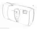
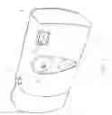
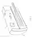
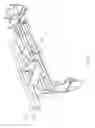
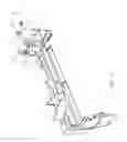
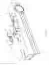
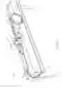
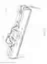
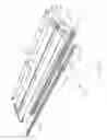
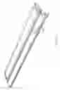

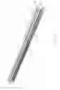


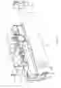

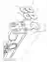
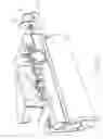

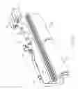
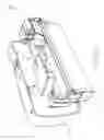
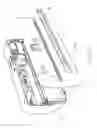
Sources:
- United States Patent and Trademark Office - verify current appl. status at the USPTO↗
Recent applications in this class:
- » 20250010608 2025-01-09
CAPPING DEVICE AND LIQUID EJECTING APPARATUS - » 20240367431 2024-11-07
INDUSTRIAL PRINTING DEVICE AND INDUSTRIAL PRINTING PROCESS - » 20240246333 2024-07-25
PRINTING DEVICE - » 20240173959 2024-05-30
RECORDING SYSTEM, RECORDING DEVICE, AND CONTROL METHOD - » 20230364905 2023-11-16
Indirect printing system - » 20230278328 2023-09-07
Friction reduction system and method - » 20220297422 2022-09-22
Recording system, post-processing apparatus, and transport apparatus - » 20220274394 2022-09-01
Friction reduction system and method - » 20220227126 2022-07-21
ESTIMATION METHOD, PRINTING METHOD AND PRINTING APPARATUS - » 20220176693 2022-06-09
Indirect printing system