Transport device for sterile media
US20070129680A1
2007-06-07
10/573,767
2004-08-24
✅ Patent granted
US 8,083,493 B2
2011-12-27
WO; PCT/EP2004/009451; 20040824
WO; WO2005/034777; 20050421
Charles Freay | Patrick Hamo
2027-10-08
Abstract:
For water-jet surgery pump devices are known by means of which a sterile fluid is transported through a reservoir to the surgical instrument by means of piston pumps or similar volumetrically transporting pumps. In accordance with the present invention it is proposed either to construct drive means for the pumps in such a way that their suction cycle is shorter than the output cycle, or to provide a pump with at least three pump chambers and to construct the drive means in such a way that the suction and output cycles of the pump chambers overlap one another.
Inventors:
- Ralf Kuhner 11 🇩🇪 Stuttgart, Germany
- Martin Hagg 18 🇩🇪 Wannweil, Germany
- Martin Hagg 1 🇩🇪 Wannwell, Germany
Assignee:
- ERBE ELEKTROMEDIZIN GMBH 73 🇩🇪 Tubingen, Germany
Interested in similar patents?
Get notified when new applications in this technology area are published.
Classification:
A61B17/3203 » CPC main
Surgical instruments, devices or methods, e.g. tourniquets; Surgical cutting instruments Fluid jet cutting instruments
A61B2090/063 » CPC further
Instruments, implements or accessories specially adapted for surgery or diagnosis and not covered by any of the groups - , e.g. for luxation treatment or for protecting wound edges; Measuring instruments not otherwise provided for for measuring volume
A61B2090/064 » CPC further
Instruments, implements or accessories specially adapted for surgery or diagnosis and not covered by any of the groups - , e.g. for luxation treatment or for protecting wound edges; Measuring instruments not otherwise provided for for measuring force, pressure or mechanical tension
A61M1/00 IPC
Suction or pumping devices for medical purposes; Devices for carrying-off, for treatment of, or for carrying-over, body-liquids; Drainage systems
F04B41/06 IPC
Pumping installations or systems specially adapted for elastic fluids Combinations of two or more pumps
Description
RELATED U.S. APPLICATIONSNot applicable.
STATEMENT REGARDING FEDERALLY SPONSORED RESEARCH OR DEVELOPMENTNot applicable.
REFERENCE TO MICROFICHE APPENDIXNot applicable.
FIELD OF THE INVENTIONThe invention relates to a device for transporting sterile fluids, e.g. Ringer solution, such as are employed for example in water-jet surgery.
BACKGROUND OF THE INVENTIONIn the area of water-jet surgery—this is an especially important example —in general the following requirements must be met:
-
- The sterility of the fluid must be ensured, because it not only comes into contact with a patient's body but also to some extent remains in the body;
- the required flow and/or the pressure needed for such flow must be substantially constant and reproducibly adjustable, to achieve a reproducible effect on the tissue;
- the person operating the device must be free to select the duration of an individual activation with constant flow;
- containers for the fluid should be available in differing sizes, so that for a particular application the amount required can be kept in reserve, with no need to exchange the container during an application on one hand and, on the other hand, without leaving a too-large container only partially emptied;
- it must be possible to begin and end the activation of the instrument substantially without delay, i.e. the pressure must build up rapidly and no drops may appear post-activity;
- it must be possible to exchange applicators with no problems.
Surgical water-jet cutting devices and associated systems for pressure build-up are known per se. One technical solution to the problem of keeping the operating fluid completely sterile, namely by preventing it from coming into any contact with parts of the pump mechanism, is disclosed by the document DE 42 00 976 C2. With this known solution, however, the user has available only a specific quantity of the fluid medium, because it is contained in a previously prepared cartridge. Once this has been opened, any content that remains cannot be put to further use, regardless of how much or how little has been extracted during the actual operation. The residue must be discarded. The maximal size of the reservoir in this known arrangement is crucially determined by the dimensions of the device. When a small device is desired, it can easily happen that the reservoir must be exchanged during the operation, which constitutes a disturbing interruption of the procedure. Furthermore, the reservoir must be pressurized as a whole, so that there is a dependence on the sizes that are available for the reservoir.
Sterile filters, which allow nonsterile transport in that they filter out any germs that could have entered the cutting medium from a nonsterile transport device, present various disadvantages. One is that the effort of maintenance is considerably increased, because the filters must be exchanged at specified time intervals. Furthermore, filters tend to inhibit the flow behavior. In the case of high pressures, inserted sterile filters are suitable only with some restrictions, because when the instrument is turned on and off they are subjected to major changes in flow and thus also interfere with the required rapid pressure build-up.
BRIEF SUMMARY OF THE INVENTIONIt is an object of the invention to provide a transport device for sterile fluids that simplifies and improves its usability in the operating theater over conventionally used devices.
According to the present invention there is provided a transport device for sterile fluids to transport a sterile medium from a reservoir or similar source to a surgical instrument, in particular an instrument for water-jet surgery or a similar consumer apparatus, which comprises a piston pump or similar volumetrically transporting pump, with a suction cycle to draw the medium in and an output cycle to eject the medium, and which furthermore comprises conduits and valve means to connect the pump to the source and to the consumer, as well as drive means to drive the pump, the drive means being constructed and connected to the pump in such a way that the suction cycle is shorter than the output cycle. Alternatively, the pump can comprise three or more pump chambers, which are actuated in such a way that the pump cycles overlap.
In the case of the first alternative the pump preferably comprises at least one first and one second piston/cylinder unit or similar pump chambers, which can be controlled in a push-pull manner so that the suction cycle in the first pump chamber is shorter than the output cycle in the second pump chamber, and conversely. As a result, only two pump chambers suffice to ensure production of a continuous flow.
The drive means are preferably constructed such that the output cycles overlap one another. This ensures an especially uniform flow, with no need for storage vessels or the like.
Each drive means is preferably constructed such that the medium is supplied to the consumer with a substantially constant pressure and hence a constant transported amount. This considerably enhances usability.
Preferably the pump is releasably connected to the drive means. As a result a “sterile device part” can be separated from an “unsterile device part” that could only be sterilized with extreme effort.
In this embodiment it is especially advantageous for the pump and/or the conduits to be constructed, preferably together with the valve means, as a “disposable unit”. Thus for each application a “set” consisting of pumps, the conduits and the necessary valve means is connected on one hand to the reservoir for the medium to be transported and on the other hand to the surgical instrument, and is then coupled to the drive means. After use this set as a whole is discarded. In this way complete sterility can be ensured along with simple manipulation, because the set can be sterilized by the manufacturer in a simple manner.
For the drive means various alternatives are possible. For instance, for each pump chamber a separately controllable drive motor can be provided, so that the velocity profile for the individual pump chambers can be set as desired with little effort, by employing an appropriate electronic control system (e.g., by using stepping motors). Alternatively (but in some cases also in addition) the drive means can be provided as gear mechanisms, with a gear train connected to the drive motor and a gear-train output for each pump chamber. Although in this case the ratio of suction cycle to output cycle cannot be changed, the transport rate can be set very easily. The complexity involved here is likewise relatively slight.
Preferred embodiments of the invention are now described by way of example with reference to the accompanying drawings.
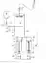
BRIEF DESCRIPTION OF THE DRAWINGSFIG. 1 is a schematic drawing of a first embodiment of the invention,
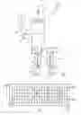
FIG. 2 is a diagram to explain the pump cycles,
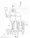
FIG. 3 shows another embodiment of the invention in a drawing similar to FIG. 1,
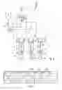
FIG. 4 is a diagram to explain the pump cycles of the arrangement according to FIG. 3, and
FIG. 5 shows a third preferred embodiment of the invention.
DETAILED DESCRIPTION OF THE INVENTIONIn the following description, the same reference numerals are used for identical parts or parts with identical actions.
In the embodiment shown in FIG. 1 there are provided a first pump 20 and a second pump 30, each of which comprises a piston 25; 35, a cylinder 26; 36, a piston rod 27; 37, and a pump conduit 21 or 31 connected to a surgical instrument 1 by way of output valves 24 and 34, respectively, and a clamp valve 2.
The pump conduits 21 and 31 are connected by way of suction conduits 22 and 32 and suction valves 23 and 33 to a suction conduit 12 that can be connected to a source 10 by way of a releasable coupling 11.
The piston rods 27 and 37 are releasably connected, by way of a first coupling 43 and second coupling 44, respectively, to a first motor 41 and second motor 42. The parts enclosed by the dashed line in FIG. 1 constitute a disposable unit, which is sterilized and placed in sterile packaging by the manufacturer and is sent in this form to the merchant and/or end user.
The drive motors 41, 42 are connected to a control means (not shown) that controls the drive motors 41, 42 in such a way that the pistons 25, 35 travel along a path s, the time course of which is illustrated in FIG. 2. As shown in FIG. 2, the suction cycles, during which the quantity s increases (so that the curves for s rise in FIG. 2), are much shorter than the output cycles (during which the curves in FIG. 2 are falling). Furthermore, the output cycles overlap in such a way that the sum of the volumes (defined by the pistons 25 and 35 as well as the cylinders 26 and 36) per unit time remains the same, with no decrease, so that a constant outflow of liquid from the source 10 to the surgical instrument 1 is ensured. As customary values for the pressure during employment in water-jet surgery, ca. 20 to 100 bar can be cited. Preferred stroke volumes of the pumps 20, 30 are between 2 and 100 ml per stroke.
The embodiment of the invention shown in FIG. 3 differs from that according to FIG. 1 primarily in that a third pump 50 with a third pump conduit 51, a third suction conduit 52, a third suction valve 53, a third output valve 54, a third piston 55, a third cylinder 56 and a third piston rod 57 are provided, as well as a third motor 45 and a third coupling 46 connected to the third piston rod 57.
In addition, in this embodiment of the invention the control means (not shown here) for the motors 41, 42 and 45 can be constructed so that the suction cycles are exactly as long as the output cycles, in which case the three cycles are arranged to be overlapping in such a way that again a uniform pump output, i.e. pumped volume per unit time, is ensured. This is indicated schematically in FIG. 4, where the curves for the individual pumps 20, 30 and 50 are identified by these reference numerals.
The additional embodiment of the invention shown in FIG. 5 corresponds to the one in FIG. 3 except that no separate pump motors 41, 42 and 45 are provided. Instead the drive means 40 comprises a single motor 64, the shaft 65 of which is connected to a gear arrangement 60 comprising three gear mechanisms 61, 62 and 63, each of which drives a pump 20, 30 and 50, respectively. The gear mechanisms 61, 62 and 63 can be constructed, for example, as disk cam mechanisms, so that the actuation cycles can be arranged similarly to those according to FIG. 4. It is of course also possible to use a drive means 40 designed in this way with the embodiment according to FIG. 1.
List of Reference Numerals
- 1 Surgical instrument
- 2 Clamp valve
- 10 Source
- 11 Coupling
- 12 Suction conduit
- 20 1st pump
- 21 1st pump conduit
- 22 1st suction conduit
- 23 1st suction valve
- 24 1st output valve
- 25 1st piston
- 26 1st cylinder
- 27 1st piston rod
- 30 2nd pump
- 31 2nd pump conduit
- 32 2nd suction conduit
- 33 2nd suction valve
- 34 2nd output valve
- 35 2nd piston
- 36 2nd cylinder
- 37 2nd piston rod
- 40 Drive means
- 41 1st motor
- 42 2nd motor
- 43 1st coupling
- 44 2nd coupling
- 45 3rd motor
- 46 3rd coupling
- 50 3rd pump
- 51 3rd pump conduit
- 52 3rd suction conduit
- 53 3rd suction valve
- 54 3rd output valve
- 55 3rd piston
- 56 3rd cylinder
- 57 3rd piston rod
- 60 Gear arrangement 1s 61 1st part of gear arrangement
- 62 2nd part of gear arrangement
- 63 3rd part of gear arrangement
- 64 Motor
- 65 Shaft
Claims
1. Transport device for sterile fluids to transport a sterile fluid from a source to a consumer, comprising
a pump that transports volumetrically, with a suction cycle for drawing in said fluid and an output cycle for ejecting said fluid;
conduit and valve devices for connecting said pump to the source and to said consumer; and
drive means to drive said pump, that is constructed and connected to said pump in such a way that said suction cycle is shorter than said output cycle.
2. Transport device for sterile fluids to transport a sterile fluid from a source to a consumer comprising
a pump that defines at least three pump chambers and that transports volumetrically, with a suction cycle for drawing in said fluid and an output cycle for ejecting said fluid;
conduit and valve devices for connecting said pump to said source and to said consumer; and
drive means to drive said pump, that is constructed in such a way that the suction and output cycles of said pump chambers overlap one another.
3. Transport device according to claim 1, wherein said pump comprises at least one first and one second piston/cylinder unit defining first and second pump chambers, which can be controlled in a push-pull manner in such a way that said suction cycle in said the first pump chamber is shorter than said the output cycle in said second pump chamber (35, 36) and conversely.
4. Transport device according to claim 1, wherein said drive means is constructed in such a way that said output cycles overlap.
5. Transport device according to claim 1, wherein said drive means is constructed in such a way that said fluid is supplied to said consumer with a substantially constant pressure.
6. Transport device according to claim 1, wherein said pump is releasably connected to said drive means.
7. Transport device according to claim 6, wherein at least one of said pump, said conduits, and said valve means, is constructed as a disposable unit.
8. Transport device according to claim 2, wherein said drive means for each pump chamber comprises a separate, controllable drive motor.
9. Transport device according to claim 1, wherein said drive means comprises a single controllable drive motor and gear mechanisms with a gear-train input connected to said drive motor and a gear-train output for each said pump chamber.
10. Transport device according to claim 2, wherein said drive means is constructed in such a way that said output cycles overlap.
11. Transport device according to claim 2, wherein said drive means is constructed in such a way that said fluid is supplied to said consumer with a substantially constant pressure.
12. Transport device according to claim 2, wherein said pump is releasably connected to said drive means.
13. Transport device according to claim 2, wherein said drive means comprises a single controllable drive motor and gear mechanisms with a gear-train input connected to said drive motor and a gear-train output for each said pump chamber.
Images & Drawings included:
Sources:
- United States Patent and Trademark Office - verify current appl. status at the USPTO↗
Recent applications in this class:
- » 20250288314 2025-09-18
WATER JET CUTTER TRAJECTORY PRESETTING APPARATUS, COMPUTER-READABLE STORAGE MEDIUM, AND ELECTRONIC DEVICE - » 20250255638 2025-08-14
SYSTEMS AND METHODS FOR ENDOLUMINAL VALVE CREATION - » 20250169847 2025-05-29
MEDICAL WATER JET SCALPEL DEVICE AND MEDICAL WATER JET SCALPEL SYSTEM - » 20250169846 2025-05-29
TIP FOR NEUROSURGICAL ROBOT - » 20250143740 2025-05-08
USER INTERFACE AND IMAGE GUIDED TREATMENT PLANNING - » 20250143739 2025-05-08
TRANSURETHRAL TREATMENT PROBE AND IMAGE GUIDED TREATMENT - » 20250134547 2025-05-01
TRANSURETHRAL TREATMENT DEVICE - » 20250120737 2025-04-17
TISSUE RESECTION SYSTEM AND METHOD FOR DETERMINING CUTTING PARAMETER - » 20250120736 2025-04-17
MULTI-IMAGE INFORMATION FUSION SYSTEM AND METHOD FOR TISSUE CUTTING PATH PLANNING - » 20250040954 2025-02-06
AUTOMATIC WATER JET CUTTER SYSTEM
Recent applications for this Assignee:
- » 20190117292 2019-04-25
Electrosurgical instrument - » 20190008537 2019-01-10
Surgical instrument with two-stage actuation gear mechanism - » 20180140342 2018-05-24
Cryoprobe and method of manufacturing the same - » 20170360416 2017-12-21
Cryosurgical instrument - » 20170071653 2017-03-16
Ablation device for large-area mucosal ablation - » 20170071652 2017-03-16
Ablation system for large-area surface coagulation of biological tissue - » 20170065331 2017-03-09
Instrument for grasping, dissecting and/or coagulating biological tissue - » 20170049505 2017-02-23
Coagulation and dissecting instrument with improved control - » 20160331438 2016-11-17
Electrosurgical instrument and device with such an instrument - » 20160287320 2016-10-06
Tissue scissors for biological tissue