Method for combining heat conductive tubes with heat dissipating fins
US20070137035A1
2007-06-21
11/304,557
2005-12-16
Abstract:
A method for combining heat conductive tubes and heat dissipating fins includes the steps of positioning heat conductive tubes, extending the heat conductive tubes through holes in a very first heat dissipating fin, placing solder rings around each of the heat conductive tubes and between the heat conductive tubes and the very first heat dissipating fin, repeating the heat conductive tube extending step and the solder ring placing step until the solder rings are placed between the heat conductive tubes and a very last heat dissipating fin and heating a combination of the heat conductive tubes, the heat dissipating fins and the solder rings to melt the solder rings so as to secure engagement between the heat conductive tubes and the heat dissipating fins.
Interested in similar patents?
Get notified when new applications in this technology area are published.
Classification:
B21C37/22 » CPC main
Manufacture of metal sheets, bars, wire, tubes or like semi-manufactured products, not otherwise provided for; Manufacture of tubes of special shape of tubes or metal hoses; Combined procedures for making tubes, e.g. for making multi-wall tubes; Making tubes of special shape; Making tube fittings Making finned or ribbed tubes by fixing strip or like material to tubes
B21C37/24 » CPC further
Manufacture of metal sheets, bars, wire, tubes or like semi-manufactured products, not otherwise provided for; Manufacture of tubes of special shape of tubes or metal hoses; Combined procedures for making tubes, e.g. for making multi-wall tubes; Making tubes of special shape; Making tube fittings; Making finned or ribbed tubes by fixing strip or like material to tubes annularly-ribbed tubes
B23K1/0012 » CPC further
Soldering, e.g. brazing, or unsoldering specially adapted for particular articles or work Brazing heat exchangers
F28F1/32 » CPC further
Tubular elements; Assemblies of tubular elements; Tubular elements and assemblies thereof with means for increasing heat-transfer area, e.g. with fins, with projections, with recesses the means being only outside the tubular element and extending transversely the means having portions engaging further tubular elements
B23K2101/14 » CPC further
Articles made by soldering, welding or cutting; Tubular or hollow articles Heat exchangers
F28F2275/06 » CPC further
Fastening; Joining by welding
Y10T29/4935 » CPC further
Metal working; Method of mechanical manufacture Heat exchanger or boiler making
B21D53/02 IPC
Making other particular articles heat exchangers , e.g. radiators, condensers
Description
BACKGROUND OF THE INVENTION1. Field of the Invention
The present invention relates to a method for combining heat conductive tube with heat dissipating fins, and more particularly to a method with which solder rings are employed to secure engagement between the heat conductive tubes and the heat dissipating fins.
2. Description of Related Art
Due to the fast operational speed of electronic appliances, heat dissipation becomes the major problem to maintain the electronic appliances to work normally. Numerous devices are developed to the market to rapidly dissipate the heat from the electronic appliances, however, some of them still suffer from different drawbacks. The most common heat dissipating device is composed of a fan assembly to use air flow to take away the heat resulted from the high rotational speed of the electronic appliance e.g. CPU. Another heat dissipating device is to use a fan assembly and a heat sink having multiple heat dissipating fins formed on the heat sink. Thus when the heat sink receives heat from the electronic appliance, the air flow from the fan assembly is able to effectively take the heat away from the heat sink so as to lower the electronic appliance's temperature.
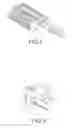
With reference to FIGS. 4 and 5, a different conventional heat dissipating device is to use a combination of heat sink and a heat conductive tube (1). The heat sink has multiple heat dissipating fins (2) securely connected to each other and respectively having a through hole (3) defined through the heat dissipating fin (2) and a cutout (5) defined in each of the heat dissipating fins (2) to communicate with the through hole (3). After the heat conductive tube (1) is inserted into the through hole (3) of the heat sink, a metal wire (6), as shown in FIG. 5, is then inserted into the cutouts (5) of the heat sink. Thereafter, a heating process is employed to melt the metal wire (6) to allow the molten metal to flow allover the heat conductive tube (1) so as to securely connect the heat conductive tube (1) to the heat sink. However, the heating process to melt the metal wire (6) so as to secure the engagement between the heat conductive tube (1) and the heat sink will damage the heat conductive tube (1) if the material of the heat conductive tube (1) is the same as that of the metal wire (6), or at least has a similar melting point.
To overcome the shortcomings, the present invention tends to provide an improved method to mitigate the aforementioned problems.
SUMMARY OF THE INVENTIONThe primary objective of the present invention is to provide a method for combining heat conductive tubes with heat dissipating fins.
In one aspect of the present invention, the method of the present invention includes the following steps:
positioning heat conductive tubes;
extending the heat conductive tubes through holes in a very first heat dissipating fin;
placing solder rings around each of the heat conductive tubes and between the heat conductive tubes and the very first heat dissipating fin;
repeating the heat conductive tube extending step and the solder ring placing step until the solder rings are placed between the heat conductive tubes and a very last heat dissipating fin; and
heating a combination of the heat conductive tubes, the heat dissipating fins and the solder rings to melt the solder rings so as to secure engagement between the heat conductive tubes and the heat dissipating fins.
In yet another aspect of the present invention, it is noted that the holes in each of the heat dissipating fins has a substantially U shaped cross section so that each solder ring is able to be rested in a corresponding one of the holes in the solder ring placing step.
Other objects, advantages and novel features of the invention will become more apparent from the following detailed description when taken in conjunction with the accompanying drawings.
BRIEF DESCRIPTION OF THE DRAWINGSFIG. 1 is a flow chart showing the steps of the method of the present invention;
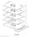
FIG. 2 is an exploded perspective view showing the assembly process of the present invention;
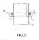
FIG. 3 is a schematic cross section showing the engagement between the heat conductive tube and a corresponding heat dissipating fin;
FIG. 4 is a perspective view showing a conventional combination of heat conductive tubes and heat dissipating fins; and
FIG. 5 is an partially enlarged perspective view showing the structure between the heat conductive tube and the heat dissipating fin.
DETAILED DESCRIPTION OF THE PREFERRED EMBODIMENTWith reference to FIG. 1, it is noted that the method in accordance with the present invention includes the following steps:
(1) positioning heat conductive tubes;
(2) extending the heat conductive tubes through holes in a very first heat dissipating fin;
(3) placing solder rings around each of the heat conductive tubes and between the heat conductive tubes and the very first heat dissipating fin;
repeating the heat conductive tube extending step and the solder ring placing step until the solder rings are placed between the heat conductive tubes and a very last heat dissipating fin; and
(4) heating a combination of the heat conductive tubes, the heat dissipating fins and the solder rings to melt the solder rings so as to secure engagement between the heat conductive tubes and the heat dissipating fins.
With reference to FIG. 2, it is noted that to implement the method of the present invention, the operator has to first prepare and position multiple heat conductive tubes (10) in place. Then a very first heat dissipating fin (11) with holes (12) defined therethrough and positioning shoulders (13) respectively defined in inner side faces of the holes (12) is prepared. That is, each hole (12) has a positioning shoulder (13) defined in an inner side face defining the hole (12). After extending the heat conductive tubes (10) through the holes (12) in the very first heat dissipating fin (11) and securing the very first heat dissipating fin (11) on the heat conductive tubes (10) via friction therebetween, solder rings (14) are applied to be rested in the shoulders (13) in each of the holes (12). Then the operator repeats the aforementioned process until the solder rings (14) are rested in the shoulders (13) in the very last heat dissipating fin (11). After the combination of the heat conductive tubes (10), the heat dissipating fins (11) and the solder rings (14) is finished, the operator heats the combination to melt the solder rings (14) so as to secure engagement between the heat conductive tubes (10) and the heat dissipating fins (11), which completes the combination between the heat conductive tubes (10) and the heat dissipating fins (11).
From the aforementioned description, it is noted that the present invention is able to easily assemble the heat conductive tubes (10) and the heat dissipating fins (11) without repeating tiresome and troublesome steps of consecutively inserting the metal wires and melting the metal wire to secure engagement between the heat conductive tubes and the heat dissipating fins.
It is to be understood, however, that even though numerous characteristics and advantages of the present invention have been set forth in the foregoing description, together with details of the structure and function of the invention, the disclosure is illustrative only, and changes may be made in detail, especially in matters of shape, size, and arrangement of parts within the principles of the invention to the full extent indicated by the broad general meaning of the terms in which the appended claims are expressed.
Claims
What is claimed is:1. A method for combining heat conductive tubes and heat dissipating fins, the method comprising the steps of:
positioning heat conductive tubes;
extending the heat conductive tubes through holes in a very first heat dissipating fin;
placing solder rings around each of the heat conductive tubes and between the heat conductive tubes and the very first heat dissipating fin;
repeating the heat conductive tube extending step and the solder ring placing step until the solder rings are placed between the heat conductive tubes and a very last heat dissipating fin; and
heating a combination of the heat conductive tubes, the heat dissipating fins and the solder rings to melt the solder rings so as to secure engagement between the heat conductive tubes and the heat dissipating fins.
2. The method as claimed in claim 1, wherein each hole has a shoulder defined in an inner periphery defining the hole so that the solder ring is able to be rested in a corresponding shoulder.
Images & Drawings included:

Sources:
- United States Patent and Trademark Office - verify current appl. status at the USPTO↗
Recent applications in this class:
- » 20110000656 2011-01-06
Method for producing a flat tube with an inner insert