Method for the filling of particulate material in vertical tubes
US20070137146A1
2007-06-21
11/578,173
2003-09-24
✅ Patent granted
US 7,753,086 B2
2010-07-13
WO; PCT/NO03/00323; 20030924
WO; WO2004/028679; 20040408
Gregory L Huson | Nicolas A Arnett
2025-10-09
Abstract:
This invention relates to a method for filling particulate material in vertical tubes (1) where the velocity of fall of the material (4) is reduced by having it glide down a rotating spiral duct (2) or by gliding down a rotating inner tube (5) with openings above the bottom (6) through which the material can fall out. The inner tube (5) is filled with the particulate material (4). After the material has fallen out of the spiral duct (2) or the inner tube (5), it can fall towards the tube's (1) wall during the drop onto the top layer of filled material.
Assignee:
- Catalyst Services, Inc. 6 🇺🇸 Deer Park, TX, United States
Interested in similar patents?
Get notified when new applications in this technology area are published.
Classification:
B65G69/16 » CPC main
Auxiliary measures taken, or devices used, in connection with loading or unloading Preventing pulverisation, deformation, breakage, or other mechanical damage to the goods or materials
B01J8/003 » CPC further
Chemical or physical processes in general, conducted in the presence of fluids and solid particles; Apparatus for such processes; Feeding of the particles in the reactor; Evacuation of the particles out of the reactor in a downward flow
B65G11/203 » CPC further
Chutes; Auxiliary devices, e.g. for deflecting, controlling speed of, or agitating articles or solids for articles
B65G11/206 » CPC further
Chutes; Auxiliary devices, e.g. for deflecting, controlling speed of, or agitating articles or solids for bulk
C01B3/384 » CPC further
Hydrogen; Gaseous mixtures containing hydrogen; Separation of hydrogen from mixtures containing it ; Purification of hydrogen; Production of hydrogen or of gaseous mixtures containing a substantial proportion of hydrogen by reaction of gaseous or liquid organic compounds with gasifying agents, e.g. water, carbon dioxide, air by reaction of hydrocarbons with gasifying agents using catalysts the catalyst being continuously externally heated
B01J2208/00752 » CPC further
Processes carried out in the presence of solid particles; Reactors therefor; Feeding or discharging of solids Feeding
B01J2208/00778 » CPC further
Processes carried out in the presence of solid particles; Reactors therefor; Feeding or discharging of solids; Details of feeding or discharging Kinetic energy reducing devices in the flow channel
C01B2203/0233 » CPC further
Integrated processes for the production of hydrogen or synthesis gas; Processes for making hydrogen or synthesis gas containing a reforming step containing a catalytic reforming step the reforming step being a steam reforming step
C01B2203/0816 » CPC further
Integrated processes for the production of hydrogen or synthesis gas; Methods of heating or cooling; Methods of heating the process for making hydrogen or synthesis gas by combustion of fuel Heating by flames
C01B2203/1011 » CPC further
Integrated processes for the production of hydrogen or synthesis gas; Catalysts for performing the hydrogen forming reactions; Arrangement or shape of catalyst Packed bed of catalytic structures, e.g. particles, packing elements
B65B1/04 IPC
Packaging fluent solid material, e.g. powders, granular or loose fibrous material, loose masses of small articles, in individual containers or receptacles, e.g. bags, sacks, boxes, cartons, cans, or jars Methods of, or means for, filling the material into the containers or receptacles
B01J8/06 » CPC further
Chemical or physical processes in general, conducted in the presence of fluids and solid particles; Apparatus for such processes with stationary particles, e.g. in fixed beds in tube reactors; the solid particles being arranged in tubes
Description
This invention relates to a method for the filling of particulate material into vertical tubes where the particulate material is conveyed down in the tube via damper devices. By particulate material is meant particles having various geometric shapes such as spheres or cylinders, or other forms of packing material made of metal or ceramic material. The size of the material should be no more than ⅕of the tube's diameter.
This method is of particular importance for the filling of catalyst for primary reforming of hydrocarbons by steam in a series of parallel reactor tubes. The height of these tubes is of about 10 m.
Pouring the particulate material into the tube from the top can lead to extensive crushing of the material, which in turn may lead to a non-homogeneous filling. Various methods for reducing the speed of the material are therefore used.
One method used is termed the sock method, where the particulate material is filled into a bag which is lowered into the tube and then opened. In this way the free fall of the material can be prevented. The disadvantage of this method is that many particles hit the top of the layer of material already filled at the same time. This may lead to the formation of bridges of material which prevents homogeneous flow of gas and leads as well to a lesser amount of filling of the catalyst in the tube. This is described by F. M. Nooy (Oil and Gas Journal, Nov. 12 1984.) and confirmed experimentally by D. J. Humberland og C. S. Crawford (The packing of particles. Handbook of powder technology, Vol IV, Elsevier 1989). By making the tube vibrate, the bridges may be made to collapse, but the material may be crushed in the process.
Another damper method which has been used was to hang a rope with blades made of Teflon mounted on it, in accordance with U.S. Pat. No. 3,608,751. The inclination of the blades was 30-45 degrees to the rope and adjacent pairs of blades had an angle of 60 degrees to each other. The distance between the blades was 2.5 feet, the blades diameter is of about 3 inches, and the tube's inner diameter is 3-5 inches. Free fall from the top of the 34 foot high tube led to the crushing of 5% of the particles, whereas only 0.9% was crushed when this rope was used. No data is given which could be used for the calculation of the density of the filling, nor any information on whether or not vibration was used. U.S. Pat. 4,077,530 describes a damping method where piano wire, shaped for example into a spiral, is made to hang down in the tube. The speed of the particles is reduced as a result of contact between the wire and the tube's inner wall. This method leads to a better packing than the sock method.
A damper device which has found favour in the industry in recent years, was developed and patented by Norsk Hydro ASA: U.S. Pat. No. 5,247,970. A series of damper brushes having a smaller diameter than the tube's inner diameter, are hung below one another inside the tube. The brushes consist of radially pointing steel springs which may be bent in all directions thus allowing particles, which fall down on the brush from above, to pass and thus reduce their speed. Like all the damper arrangements mentioned, these must be pulled up as the filling is in progress. In addition to these methods, U.S. Pat. 2,524,560 describes an apparatus and a method for filling loose dry material tightly in a cylinder which is connected to a loading device and which also provides an arrangement for the removal of dust particles. The material is filled into a tube containing a centrally situated rotating feed screw running through the whole tube and down to the upper edge of the material in the cylinder which is to be filled. The cylinder is lowered as it is filled. However such a device will not be applicable for filling of catalyst particles in tubes about 10 m in height. It would be impossible to lower the tubes as they are filled. Furthermore, the feed screw may easily crush the catalyst particles.
The main object of this invention is to achieve a dense and homogeneous packing of material so that a stream of gas passing through the tube becomes as homogeneous as possible. This is hopefully achieved by distributing the material evenly across the tube's cross-section during the filling process.
Another object of this invention is to develop gentler methods for reducing the particle speed during the filling.
The above-mentioned devices for speed dampening have the disadvantage that damper devices placed in the centre of the tube being filled, impede an even distribution of material across the cross-section. The particulate material, which falls near the inner tube wall, may, in the worst case, get a minimal speed reduction compared with the material falling near the centre of the tube.
The following examples are included in order to elucidate the invention, but are not meant to limit the extent of it.
The invention is further explained in connection with the description of the figures.
Special features of the invention and its scope are defined in the attached claims.
The essential feature of the invention, in which particulate material is filled in vertical tubes, is that the material is conveyed down via a duct formed as a spiral, or down into an inner rotating tube giving it a horizontal velocity component thereby flinging the material towards the inner wall of the vertical tube before it hits the top layer of the already filled material.
A special feature of this invention is that the particulate material is conveyed down to a rotating duct formed as a spiral.
It may also be helpful to use a spiral-shaped duct, mounted under damper devices such as gratings and/or brushes, which could rotate separately or together with the damper devices.
The invention also includes the conveying of the particulate material down into an inner tube having a bottom with openings in the tube wall above the aforementioned bottom. The material will be flung out of the inner tube, towards the wall of the vertical tube during the fall towards the top layer of filled material.
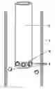
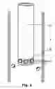
FIG. 1 shows a spiral-shaped device according to the present invention.
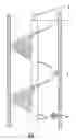
FIG. 2 shows a tube-shaped device according to the present invention.
The device according to FIG. 1 shows a tube 1, for filling of particulate material 4. In the centre of the tube I is a duct shaped as a spiral 2 which may be rotating. It can be hung up under another breaking device or from a wire from the top of tube 1 by means of a fastening device 3. The particulate material 4 is flung towards tube's 1 inner wall during the fall. Device 2 can be pulled up gradually as tube 1 is filled with material and its lower part will, during the filling, reach a little above the filled material.
The spiral-shaped device 2 may be combined to advantage with other damping devices in such a way that the spiral-shaped device 2 forms the lower part of the device while the damper devices mentioned above, form the upper part to which the particulate material is supplied.
FIG. 2 shows a vertical tube 5 filled with particles 4 which may rotate inside the tube 1, which is to be filled. The inner tube 5 has a bottom and openings in the tube wall 6 above the bottom so that the particles 4 may fall out of the tube and be flung towards the wall in tube 1 during the fall down towards the top layer of filled material.
During tests with the spiral shaped duct, it was discovered that the filling was very even and dense when the duct rotated slowly either in the same direction or in the opposite direction of the spiral's direction of twist. It was also observed that when the particulate material left the duct it had a horizontal velocity component in addition to the vertical component. When it hit the top layer, it may have a higher kinetic energy and thus may more easily find a stable position without forming a bridge.
It was therefore of interest to study how the energy the material had when it hit the top layer influences the filling. R. M. Nedderman (Granular materials, Cambridge University press 1992) has described an experiment where the void fraction was measured for fillings with free fall of various types of particles. The height of the free fall was increased from 0.05 to 2.4 m, and for cylindrical particles with height and diameter 6.35 mm the void fraction decreased from 0.38 to 0.33 respectively. This indicates that the particles' kinetic energy influences the packing of the particles.
The invention's object is the filling of particulate material, as mentioned in the introduction, into tubes in such a way that most of the material is given a horizontal velocity component just before it hits the top layer of already filled material. In principle this may probably be achieved by rotating the damper devices described earlier. However, better control, and therefore a more homogeneous filling, will be achieved with a combination of these damper devices and the spiral duct while a spiral duct is installed below the lowest damper. The shape of the spiral duct and the rotation speed has to be adjusted so that an optimal degree of filling and filling speed can be achieved.
EXAMPLE 1The purpose of this experiment is to achieve the densest packing possible as a basis for further experiments.
The filling was performed in a transparent plastic tube having an inner diameter of 10 cm and a height of about 1 m. Cylindrical catalyst particles with outer and inner diameters of 1.7 and 0.6 cm, respectively, and 1.7 cm height were used. Photographs were taken during the filling with a Canon EOS 650 camera. The photographs were taken continuously, and the shutter speed was 1/90- 1/125 sec.
The experiment aims at finding the maximum degree of filling marked by the void fraction since this quantity is used in the literature when various filling methods are compared.
The particulate material was poured slowly into the tube while it was subjected to vibration. The height of the filled layer was then measured from the bottom of the tube to the bottom of a piston which was lowered down onto the material. The piston was a cylindrical plastic box which fit snugly in the tube. The volume of filled particulate material and the total outer volume of all the material were used to calculate the void fraction. This fraction varied from 0.36 to 0.38 in 3 experiments.
EXAMPLE 2The purpose of this experiment was to show how the particulate material slides down a spiral duct and how it thereby achieves a horizontal velocity component as it is flung towards the inner wall of the tube just before-it hits the top layer of filled catalyst.
The spiral duct was an extension of an ice drill of the same type as shown in FIG. 1. The duct rotated at a speed of 3 seconds per revolution in the same direction as the twist direction of the spiral. The distance from the bottom of the tube to the lower edge of the drill was 32 cm. In 3 experiments the void fraction varied is from 0.39 to 0.42, which indicates a low void fraction.
Claims
1. Method for filling of spheres, cylinders and other types of particulate material (4), comprising metals or ceramic materials, in vertical tubes (1), in which the material (4) is conveyed down via damper devices,
characterized in that the particulate material (4) is conveyed down to a spiral shaped duct (2) or down to a rotating inner tube (5) which gives it a horizontal velocity component and thereby flings it towards the tube's (1) inner wall before it hits the top layer of filled material.
2. Method according to claim 1,
characterized in that the particulate material is conveyed down into a rotating spiral-shaped duct (2).
3. Method according to claim 1,
characterized in that a spiral-shaped duct (2) is used which is mounted below damper devices like gratings and/or brushes and which may rotate separately or together with the damper devices.
4. Method according to claim 1,
characterized in that the particulate material (4) is conveyed down an inner tube (5) having a bottom and which has openings in the tube wall (6) above the bottom, where the material (4) is flung out of the tube (5) and towards the tube's (1) wall during the fall onto the top layer of filled material.
Images & Drawings included:
Sources:
- United States Patent and Trademark Office - verify current appl. status at the USPTO↗
Recent applications in this class:
- » 20220048719 2022-02-17
System and apparatuses for loading, transporting and unloading fragile product - » 20110236164 2011-09-29
LIFT DEVICE FOR PERSONALIZATION MACHINE AND PERSONALIZATION MACHINE EQUIPPED WITH A LIFT DEVICE - » 20110066279 2011-03-17
Device and method for transporting produce over a vertical distance - » 20090142177 2009-06-04
Device to load a sintering boat with nuclear fuel pellets and loading method using said device - » 20080257686 2008-10-23
Vertical conveyor in a commissioning system for vertically conveying goods that are to be transported - » 20080014032 2008-01-17
Conveyor device having a filling device for vertical flow of material, without demixing, of powdered media - » 20070209458 2007-09-13
Device for movement of articles - » 20060233631 2006-10-19
Method for filling a vertical tube with catalyst particles - » 20060151295 2006-07-13
Conveyor system for minimizing product damage during collection - » 20060021670 2006-02-02
Grain handling device and method of its use
Recent applications for this Assignee:
- » 20110150624 2011-06-23
Catalyst loading system - » 20080298932 2008-12-04
Catalyst loading system - » 20060213575 2006-09-28
Filling tubes with catalyst and/or other particulate - » 20060096655 2006-05-11
Measuring catalyst(s) for filling reactor tubes in reactor vessels - » 10743921 2008-10-14
Cleaning and/or inspecting robot for hazardous environments including catalyst removal