Automatic coating device
US20070137565A1
2007-06-21
11/639,162
2006-12-15
✅ Patent granted
US 7,757,627 B2
2010-07-20
-
-
George R Koch, III
2029-05-06
Abstract:
An automatic coating device uses a driving motor and a conveyer to form a cyclically rotating module. An injector filled with a coating material is disposed on one side of the conveyer. When an object to be coated is disposed on the other side of the moving conveyer, the coating material is then applied onto the object by the injector. This can increase the coating speed and quality.
Inventors:
- Feng-Ku Wang 33 🇹🇼 Taipei, Taiwan
- Yi-Lun Cheng 47 🇹🇼 Taipei, Taiwan
- Chih-Kai Yang 62 🇹🇼 Taipei, Taiwan
- Chun-Lung LIN 24 🇹🇼 Taipei, Taiwan
Assignee:
- INVENTEC CORPORATION 1,949 🇹🇼 Taipei, Taiwan
Interested in similar patents?
Get notified when new applications in this technology area are published.
Classification:
B05C5/0216 » CPC main
Apparatus in which liquid or other fluent material is projected, poured or allowed to flow on to the surface of the work from an outlet device in contact or almost in contact, with the work the liquid or other fluent material being discharged through an outlet orifice by pressure, e.g. for applying liquid or other fluent material to separate articles only at particular parts of the articles by relative movement of article and outlet according to a predetermined path
B05C5/022 » CPC further
Apparatus in which liquid or other fluent material is projected, poured or allowed to flow on to the surface of the work from an outlet device in contact or almost in contact, with the work the liquid or other fluent material being discharged through an outlet orifice by pressure, e.g. for applying liquid or other fluent material to separate articles only at particular parts of the articles by relative movement of article and outlet according to a predetermined path the outlet being fixed during operation
B05C5/0254 » CPC further
Apparatus in which liquid or other fluent material is projected, poured or allowed to flow on to the surface of the work from an outlet device in contact or almost in contact, with the work the liquid or other fluent material being discharged through an outlet orifice by pressure, e.g. Coating heads with slot-shaped outlet
B05C11/028 » CPC further
Component parts, details or accessories not specifically provided for in groups - ; Apparatus for spreading or distributing liquids or other fluent materials already applied to a surface ; Controlling means therefor ; Control of the thickness of a coating by spreading or distributing liquids or other fluent materials already applied to the coated surface; Apparatus for spreading or distributing liquids or other fluent materials already applied to a surface with a body having a large flat spreading or distributing surface
B05C5/00 IPC
Apparatus in which liquid or other fluent material is projected, poured or allowed to flow on to the surface of the work
B05C11/11 IPC
Component parts, details or accessories not specifically provided for in groups - Vats or other containers for liquids or other fluent materials
B05B13/02 IPC
Machines or plants for applying liquids or other fluent materials to surfaces of objects or other work by spraying, not covered by groups - Means for supporting work; Arrangement or mounting of spray heads; Adaptation or arrangement of means for feeding work
B05C17/06 IPC
Hand tools or apparatus using hand held tools, for applying liquids or other fluent materials to, for spreading applied liquids or other fluent materials on, or for partially removing applied liquids or other fluent materials from, surfaces Stencils
Description
CROSS-REFERENCE TO RELATED APPLICATIONSThis non-provisional application claims priority under 35 U.S.C. § 119(a) on Patent Application No(s). 094222075 filed in Taiwan, R.O.C. on Dec. 16, 2005, the entire contents of which are hereby incorporated by reference.
BACKGROUND OF THE INVENTION1. Field of Invention
The invention relates to a coating device, and more particularly, to an automatic coating device driven with a conveyer.
2. Related Art
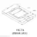
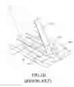
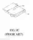
FIGS. 1A, 1B, and 1C are schematic views of manual coating according to the prior art. In usual manual coating, a lower tool 100 is used to hold an object 110 to be coated. An upper tool 130 is then disposed on the object 110. The upper tool 130 has an injection opening 131 located at the position corresponding to the position on the object 110 to be coated with the coating material 150. The coating material 150 is coated evenly in the upper tool 130 and fills the injection opening 131. A scraper 170 is used to fill the coating material 150 in the injection opening 131. After removing excess coating material 150, the upper tool 130 is taken away. Therefore, the prior method is difficult in implementing mass coating, whereas the quality cannot be guaranteed. It is thus necessary to develop a device that is suitable for mass coating.
SUMMARY OF THE INVENTIONIn view of the foregoing, an objective of the invention is to provide an automatic coating device for an object to be coated automatically, thereby promoting the coating efficiency.
To achieve the above objective, an automatic coating device disclosed herein uses a driving motor and a conveyer to form a cyclically rotating module. An injector filled with a coating material is disposed on one side of the conveyer. When an object to be coated is disposed on the other side of the moving conveyer, the coating material is then applied by the injector onto the object.
An injection opening is form in the conveyer according to the coating shape. When the injector is aimed at the injection opening, the coating material is coated onto the object via the injection opening of the conveyer.
The injector includes a body and an extension board. The body holds the coating material and has an outlet for the coating material to escape from the body. The extension board is connected to the outlet and touches the surface of the conveyer. When the injection opening aligns with the outlet so that the coating material is applied onto the object via the outlet, the extension board pushes the coating material to fill the injection opening. The coating material is thus coated onto the object in accord with the shape of the injection opening.
The disclosed automatic coating device achieves the above goal in an automatic way. Therefore, it has a high coating efficiency, stability, and quality. The extension board provided to pass through the surface of the injection opening enables the coating material to fill the injection opening. Thus, no coating material would be wasted. One can change the thickness and shape of the coating by merely changing the thickness of the conveyer and the shape of the injection opening. Consequently, the disclosed automatic coating device has the advantages of fast coating and highly adaptive for different products.
Further scope of applicability of the present invention will become apparent from the detailed description given hereinafter. However, it should be understood that the detailed description and specific examples, while indicating preferred embodiments of the invention, are given by way of illustration only, since various changes and modifications within the spirit and scope of the invention will become apparent to those skilled in the art from this detailed description.
BRIEF DESCRIPTION OF THE DRAWINGSThe present invention will become more fully understood from the detailed description given hereinbelow illustration only, and thus are not limitative of the present invention, and wherein:
FIGS. 1A, 1B, and 1C are schematic views of manual coating;
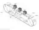
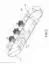
FIG. 2 is an assembly view of the invention;
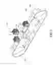
FIG. 3 is an exploded view of the invention;
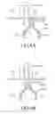
FIGS. 4A, 4B, 4C, and 4D show the action of filling the coating material according to the invention; and
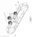
FIG. 5 is an exploded view of another embodiment of the invention.
DETAILED DESCRIPTION OF THE INVENTIONReferring to FIGS. 2, 3 and 4A, an automatic coating device 500 according to the invention can automatically coat a coating material 570 onto an object 300 to be coated, avoiding the time-consuming manual coating. As shown in FIGS. 2, 3 and 4A, the automatic coating device 500 includes a driving motor 510, a conveyer 530, and an injector 550. The driving motor 510 drives the conveyer 530 to cyclically rotate. A plurality of injection openings 531 are formed on the conveyer 530. The object 300 is disposed on one side of the conveyer 530 so that the coating area of the object 300 is exposed by one of the injection opening 531. The object 300 is temporally fixed on the conveyer 530 and driven by the conveyer 530 into motion.
The injector 550 includes a body 551 and an extension board 553. The body 551 accommodates the coating material 570. The body 551 is formed with an outlet 552, through which the coating material 570 leaves the body 551. The extension board 553 is protruded from the body 551 and beside the outlet 552 so that the surface of the extension board 553 touches the surface of the conveyer 530. When the injection opening 531 aligns with the outlet 552 for applying the coating material 570 onto the object 300 via the outlet 552, the extension board 553 pushes the coating material 570 to fill the injection opening 531 until the coating is completed.
Referring to FIGS. 4A, 4B, 4C, and 4D, the injector 550 is disposed on the other side of the conveyer 530. The injector 550 holds the coating material 570. When the injector 550 aligns with the injection opening 531, the coating material 570 leaves the injector 550 and arrives on the coating area of the object 300 via the injection opening 531. When the injector 550 does not align with the injection opening 531, the conveyer 530 prevents the coating material 570 from escaping the injector 550. Therefore, the automatic coating device 500 continuously conveys the objects 300 to be coated for the injector 550 to spray the coating material 570 on the coating area of the object 300 with uniform coating thickness.
Referring to FIGS. 3 and 5, a plurality of fixing hole 533 are formed next to the injection opening 531, and the corresponding fixing holes are also formed on the object 300. Furthermore, the object 300 is provided with fixing pins 310 at positions corresponding to the fixing holes 533. When the object 300 is disposed on the conveyer 530, the fixing pins 310 are inserted into the fixing holes 533 so that the object 300 is held at the injection opening 531. This enables the object 300 to move under the driving force of the conveyer 530. Besides, the fixing pins 310 can be replaced by screws 330. As the object 300 is fixed on other elements (not shown) using the screws 330, the object 300 is positioned and fixed on the conveyer 530 by the screws 330 thereon.
Therefore, the automatic coating device 500 of the present invention can replace the time-consuming manual coating. It can increase the coating efficiency and quality. On the other hand, using the extension board to pass through the surface of the injection opening enables the coating material to fill the entire injection opening without wasting. Changing the thickness of the conveyer changes the thickness of coating. Changing the shape of the injection opening also changes the shape of the coating material. Therefore, in addition to rapid coating, the disclosed automatic coating device has the advantage of being adaptive for different products.
The invention being thus described, it will be obvious that the same may be varied in many ways. Such variations are not to be regarded as a departure from the spirit and scope of the invention, and all such modifications as would be obvious to one skilled in the art are intended to be included within the scope of the following claims.
Claims
What is claimed is:1. An automatic coating device, comprising:
a driving motor;
a conveyer driven by the driving motor to cyclically rotate and having at least one opening for an object to be coated and driven to move by the conveyer; and
an injector, which accommodates a coating material and pushes the coating material to be applied onto the object to be coated when it aligns with the injection openings.
2. The automatic coating device of claim 1, wherein at least one fixing hole is formed next to the injection opening, and at least one fixing component corresponding to the fixing holes is provides, so that the object is held on the injection opening by insert the fixing component into the fixing hole, and thus the object is driven by the conveyer to move.
3. The automatic coating device of claim 2, wherein the fixing component is a fixing pin.
4. The automatic coating device of claim 2, wherein the fixing component is a screw.
5. The automatic coating device of claim 1, wherein the injector comprises:
a body, which accommodates the coating material and has an outlet for the coating material to leave the body; and
an extension board, which is protruded from the body and beside the outlet so that the surface of the extension board touches the surface of the conveyer;
wherein when the outlet aligns with the injection opening for the coating material to be applied onto the object, pushes the coating material to fill the injection opening.
Images & Drawings included:

Sources:
- United States Patent and Trademark Office - verify current appl. status at the USPTO↗
Similar patent applications:
- » 20230106001
AUTOMATIC ACTIVATOR COATING DEVICE FOR WIRE AND ARC ADDITIVE MANUFACTURE - » 20230349692
Type of device(s) for automatically monitoring a coating and/or structure applied to a substrate with determination of reflective properties and/or geometric dimensions, and a corresponding method - » 20070169691
Automatic retouching device for a powder-coating booth
Recent applications in this class:
- » 20250128284 2025-04-24
FLUID APPLICATOR WITH PROPORTIONAL VALVE - » 20250114817 2025-04-10
METHOD OF FORMING A LEADING-EDGE PROTECTOR - » 20250073740 2025-03-06
SEMI-AUTONOMOUS RAIL GLUING SYSTEM - » 20240424520 2024-12-26
ROBOTIC GAP FILLER APPLICATION STATION - » 20240390931 2024-11-28
METHOD AND COMPUTER PROGRAM PRODUCT FOR DETERMINING THE SHAPE OF A DISPENSING PATH AND A LOCAL APPLICATION AMOUNT OF A FLOWABLE FILLING MATERIAL - » 20240342743 2024-10-17
Apparatus and Method for the Manufacture of Noodles - » 20220266288 2022-08-25
Applicator for applying a sealing compound onto an edging fold - » 20210101173 2021-04-08
HVAC Round Pipe Sealed Fittings - » 20210053089 2021-02-25
Insulating glass unit final sealing assembly and method - » 20200324311 2020-10-15
DEVICE FOR DEPOSITING A BEAD OF A PLASTIC SUBSTANCE AND METHOD FOR IMPLEMENTING SAME
Recent applications for this Assignee:
- » 20250292381 2025-09-18
ANALYSIS METHOD AND RELATED SYSTEM FOR IMAGE DATA UNDER PRESSURE - » 20250292167 2025-09-18
Production Management Analysis Method and Production Management System - » 20250291784 2025-09-18
Data Processing System - » 20250291775 2025-09-18
Data Processing Method and Data Processing System - » 20250280508 2025-09-04
COOLING SYSTEM - » 20250280507 2025-09-04
COOLING SYSTEM - » 20250189601 2025-06-12
SYSTEM, DEVICE AND METHOD FOR DETERMINING TEST RESULT BASED ON OUTPUT VOLTAGES OF USB INTERFACE - » 20250189582 2025-06-12
SELF-FUNCTIONAL DETECTION SYSTEM FOR TAP CONTROLLER AND METHOD THEREOF - » 20250189581 2025-06-12
JTAG STANDARD PIN TEST SYSTEM - » 20250165652 2025-05-22
Application permission establishment method and application permission establishment system