Apparatus for adjusting phase between the different phases in power line communication system
US20070138867A1
2007-06-21
11/582,960
2006-10-19
Abstract:
Provided is an apparatus for adjusting the phase difference between different phases in a power line communication (PLC) system. The apparatus includes a power signal blocking unit blocking a power signal and allowing a data signal to pass between two different phases on three-phase power lines; and a data signal delaying unit delaying the data signal by the phase difference between the two different phases. Accordingly, it is possible to prevent data collision and a time delay in data transmission between different phases by employing the phase adjusting apparatus in a PLC system, thereby improving the performance of PLC.
Inventors:
- Ji-Hoon KIM 40 🇰🇷 Hwaseong-si, South Korea
- Joon-Hee Lee 23 🇰🇷 Gunpo-si, South Korea
- Ho Jeong YOU 28 🇰🇷 Suwon-si, South Korea
- In-hwan KIM 26 🇰🇷 Suwon-si, South Korea
- Jun-hae CHOI 19 🇰🇷 Seongnam-si, South Korea
- Ju-Han Lee 18 🇰🇷 Suwon-si, South Korea
- Seung-Gi Chang 12 🇰🇷 Seoul, South Korea
Interested in similar patents?
Get notified when new applications in this technology area are published.
Classification:
H02J13/00009 » CPC main
Circuit arrangements for providing remote indication of network conditions, e.g. an instantaneous record of the open or closed condition of each circuitbreaker in the network; Circuit arrangements for providing remote control of switching means in a power distribution network, e.g. switching in and out of current consumers by using a pulse code signal carried by the network characterised by information or instructions transport means between the monitoring, controlling or managing units and monitored, controlled or operated power network element or electrical equipment using the power network as support for the transmission using pulsed signals
H02J13/0001 » CPC further
Circuit arrangements for providing remote indication of network conditions, e.g. an instantaneous record of the open or closed condition of each circuitbreaker in the network; Circuit arrangements for providing remote control of switching means in a power distribution network, e.g. switching in and out of current consumers by using a pulse code signal carried by the network characterised by information or instructions transport means between the monitoring, controlling or managing units and monitored, controlled or operated power network element or electrical equipment using the power network as support for the transmission using modification of a parameter of the network power signal
Y02B90/20 » CPC further
Enabling technologies or technologies with a potential or indirect contribution to GHG emissions mitigation Smart grids as enabling technology in buildings sector
Y02B90/20 » CPC further
Enabling technologies or technologies with a potential or indirect contribution to GHG emissions mitigation Smart grids as enabling technology in buildings sector
Y02E60/00 » CPC further
Enabling technologies; Technologies with a potential or indirect contribution to GHG emissions mitigation
Y02E60/00 » CPC further
Enabling technologies; Technologies with a potential or indirect contribution to GHG emissions mitigation
Y04S10/52 » CPC further
Systems supporting electrical power generation, transmission or distribution; Systems or methods supporting the power network operation or management, involving a certain degree of interaction with the load-side end user applications Outage or fault management, e.g. fault detection or location
Y04S40/121 » CPC further
Systems for electrical power generation, transmission, distribution or end-user application management characterised by the use of communication or information technologies, or communication or information technology specific aspects supporting them characterised by data transport means between the monitoring, controlling or managing units and monitored, controlled or operated electrical equipment using the power network as support for the transmission
H02J3/02 IPC
Circuit arrangements for ac mains or ac distribution networks using a single network for simultaneous distribution of power at different frequencies; using a single network for simultaneous distribution of ac power and of dc power
G05B11/01 IPC
Automatic controllers electric
G08B1/08 IPC
Systems for signalling characterised solely by the form of transmission of the signal using electric transmission ; transformation of alarm signals to electrical signals from a different medium, e.g. transmission of an electric alarm signal upon detection of an audible alarm signal
Description
CROSS-REFERENCE TO RELATED PATENT APPLICATIONS
This application claims the priority of Korean Patent Application No. 2005-125451, filed on Dec. 19, 2005, in the Korean Intellectual Property Office, the disclosure of which is incorporated herein in its entirety by reference.
BACKGROUND OF THE INVENTION
1. Field of the Invention
The present invention relates to data transmission, and more particularly, to an apparatus for adjusting the phase difference between different phases in a power line communication (PLC) system.
2. Description of the Related Art
Different phases are out of phase by 120 degrees in a power line communication (PLC) system that uses three phases and four power lines. Thus, when data is transmitted between the same phases, the data may collide with data transmitted from a different phase, and when data is transmitted between different phases, a time delay that delays transmission of the data until a next period may occur.
SUMMARY OF THE INVENTION
The present invention provides an apparatus for adjusting the phase difference between different phases in a power line communication (PLC) system that uses three phases and four power lines, thereby preventing data collision and a time delay in the different phases.
According to an aspect of the present invention, there is provided A phase adjusting apparatus for use in a power line communication system, comprising a power signal blocking unit blocking a power signal and allowing a data signal to pass between two different phases on three-phase power lines, and a data signal delaying unit delaying the data signal by the phase difference between the two different phases.
The frequency of the data signal may be higher than a frequency of the power signal. The power signal blocking unit may comprise a capacitor which has frequency characteristics that block the power signal of low frequency but allow the data signal of high frequency to pass through it.
The data signal delaying unit may comprise a first signal transmission unit delaying a data signal transmitted from a phase A, which is one of the two different phases, by the phase difference between the phase A and the other phase B, and transmitting the delayed data signal to the phase B; and a second signal transmission unit delaying a data signal transmitted from the phase B by the phase difference between the phases B and A, and transmitting the delayed data signal to the phase A.
The first signal transmission unit may comprise an isolator blocking the data signal transmitted from the phase B; and a phase delayer delaying the data signal transmitted from the phase A by the phase difference between the phases A and B.
The phase delayer preferably delays the data signal for a fixed amount of time at all of frequencies available. The phase delayer more preferably includes a Bessel type filter.
BRIEF DESCRIPTION OF THE DRAWINGS
The above and other aspects and advantages of the present invention will become more apparent by describing in detail exemplary embodiments thereof with reference to the attached drawings in which:
FIG. 1 is a diagram of a power line communication (PLC) system that uses three phases and four power lines;
FIG. 2 is a circuit diagram of an equivalent circuit of the PLC system illustrated in FIG. 1;
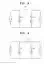
FIG. 3 is a diagram illustrating a connection between phases T and S for PLC;
FIG. 4 is a diagram illustrating a connection between the phases T and S illustrated in FIG. 3 via a capacitor;
FIG. 5 is a waveform diagram of signals used for PLC;
FIG. 6 is a diagram illustrating communications established between PLC apparatuses on the same phases in the system illustrated in FIG. 4;
FIG. 7 is a diagram illustrating communications established between PLC apparatuses on different phases in the system illustrated in FIG. 4;
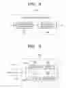
FIG. 8 is a block diagram of a phase adjusting apparatus according to an embodiment of the present invention;
FIG. 9 is a block diagram of a phase adjusting apparatus according to another embodiment of the present invention;
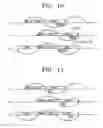
FIG. 10 is a waveform diagram of data signals exchanged between PLC apparatuses on the same phases in a PLC system employing a phase adjusting apparatus according to an embodiment of the present invention; and
FIG. 11 is a waveform diagram of data signals exchanged between PLC apparatuses on different phases in a PLC system employing a phase adjusting apparatus according to an embodiment of the present invention.
DETAILED DESCRIPTION OF THE INVENTION
A phase adjusting apparatus for use in a power line communication (PLC) system according to embodiments of the present invention will now be described with reference to the accompanying drawings.
FIG. 1 is a diagram of a PLC system that uses three phases and four power lines. Referring to FIG. 1, the PLC system includes a neural line N, and different three phases R, S, and T that are out of phases by 120 degrees.
In FIG. 1, L#1 connects the load between the phase T and the neural line N, L#2 connects the load between the phase S and the neural line N, and L#3 connects the load between the phase R and the neural line N.
FIG. 2 is a circuit diagram of an equivalent circuit of the PLC system illustrated in FIG. 1. Different three phases R, S, and T are out of phase by 120 degrees. The following equations are satisfied when a maximum voltage of each phase is 220 V:
V a = 220 * sin ( ω t - 4 π 3 ) ( 1 ) V b = 220 * sin ( ω t - 2 π 3 ) ( 2 ) V c = 220 * sin ( ω t ) ( 3 )
From Equations (1) through (3), it is noted that the three phases R, S, and T are out of phase by 2π/3 radian, i.e., by 120 degrees.
ω expressed in Equations (1) through (3) denotes the angular frequency of a power signal, satisfying the following:
w=2πf (4),
wherein f denotes the frequency of a power signal. In general, the power signal has a low frequency from 50 Hz to 60 Hz.
FIG. 3 is a diagram illustrating a connection between phases T and S for PLC. Referring to FIG. 3, the connector 100 that connects the phases T and S is needed to establish communications between a PLC apparatus on the phase T of a voltage Vc and a PLC apparatus on the phase S of a voltage Vb.
FIG. 4 is a diagram illustrating a connection between the phases T and S illustrated in FIG. 3 via a capacitor 150. The capacitor 150 has frequency characteristics that block a low-frequency signal but allow a high-frequency signal to pass through it. The frequency of a data signal used in PLC is preferably higher than that of a power signal.
FIG. 5 is a waveform diagram of signals used in PLC. In FIG. 5, a low-frequency signal denotes a power signal and a high-frequency signal denotes a data signal.
It is possible to block the power signal and allow the data signal to pass between the phases T and S by using the capacitor, illustrated in FIG. 4, which has frequency characteristics that blocks the power signal of a low frequency but allows the data signal of a high frequency to pass through it.
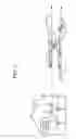
FIG. 6 is a diagram illustrating communications established between PLC apparatuses on the same phases in the system illustrated in FIG. 4. Referring to FIG. 6, communications are established between apparatuses a and b on L#1, and between apparatuses c and d on L#2. In this case, data transmission sections in L#1 and L#2 are out of phase by the phase difference between power signals in L#1 and L#2. Referring to FIG. 6, if data is transmitted from the apparatus a to the apparatus b in a TDMA section in L#1, the data may collide with data transmitted between the apparatuses c and d in a TDMA section in L#2.
FIG. 7 is a diagram illustrating communications established between PLC apparatuses on different phases in the system illustrated in FIG. 4. In detail, FIG. 7 illustrates data communications established between an apparatus a on L#1 and an apparatus c on L#2.
Referring to FIG. 7, a beacon period for L#1 does not correspond to a beacon period for L#2. To transmit data to the apparatus a in a TDMA section for L#2, the apparatus c determines whether a time slot is assigned to a TDMA section for L#1 and then transmits the data to the apparatus a. If a time slot is not allocated in the same section in which the apparatus c receives data from the apparatus a, the apparatus c cannot transmit data to the apparatus a, and thus transmits the data to the apparatus a in the next TDMA section, thereby causing a time delay.
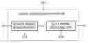
FIG. 8 is a block diagram of a phase adjusting apparatus 200 according to an embodiment of the present invention. It is possible to prevent data collision or a time delay between different phases by using the phase adjusting apparatus 200 in place of the connector 100 illustrated in FIG. 3.
Referring to FIG. 8, the phase adjusting apparatus 200 may include a power signal blocking unit 210 and a data signal delaying unit 220.
The power signal blocking unit 210 blocks a power signal between different phases but allows a data signal to pass between the different phases. The data signal delaying unit 220 delays transmission of the data signal by the phase difference of power signals between the two phases.
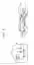
FIG. 9 is a block diagram of another embodiment of the phase adjusting apparatus 200 according to the present invention. In FIG. 9, it is assumed that a power signal blocking unit 210 is connected to a phase A and a data signal delaying unit 220 is connected to a phase B.
The power signal blocking unit 210 may include a capacitor 211 that has frequency characteristics that block a power signal of a low frequency but allow a data signal of a high frequency to pass through it.
The data signal delaying unit 220 may include a first signal transmission unit 230 and a second signal transmission unit 240. The first signal transmission unit 230 delays a data signal received from the phase A by the phase difference between the phases A and B, and transmits the delayed data signal to the phase B. The second signal transmission unit 240 delays a data signal received from the phase B by the phase difference between the phases B and A, and transmits the delayed data signal to the phase A.
The first signal transmission unit 230 may include a first isolator 232 and a first phase delayer 234, and the second signal transmission unit 240 may include a second isolator 242 and a second phase delayer 244. The first and second isolators 232 and 242 respectively block the data signals received from the phases B and A, thereby preventing the data signals from interfering with each other. The first delayer 234 delays the data signal received from the phase A by the phase difference between the phases A and B, and transmits the delayed data signal. The second delayer 244 delays the data signal received from the phase B by the phase difference between the phases B and A, and transmits the delayed data signal. The locations of the first isolator 232 and the first phase delayer 234, and the locations of the second isolator 242 and the second phase delayer 244 may be switched. In this case, the functions, power consumption, or operations of them are not changed.
The delayers 234 and 244 are preferably constructed such that group delays at all of frequencies available are uniform. According to an embodiment of the present invention, the first and second phase delayers 234 and 244 may include a Bessel type filter that delays a data signal for a fixed amount of time at all of frequencies available.
FIG. 10 is a waveform diagram of data signals exchanged between PLC apparatuses on the same phases in a PLC system employing the phase adjusting apparatus 200 according to an embodiment of the present invention. Referring to FIG. 10, a data signal generated in L#1 is delayed by the phase difference between L#1 and L#2 and the delayed signal is transmitted to L#2, thereby preventing collision of data signals.
FIG. 11 is a waveform diagram of data signals exchanged between PLC apparatuses on different phases in a PLC system employing the phase adjusting apparatus 200 according to an embodiment of the present invention. Referring to FIG. 11, a beacon section in L#1 corresponds to a beacon section on L#2. In the beacon section, an agreement regarding assignment of a time slot for a CSMA section and a TDMA section is made between apparatuses. Therefore, since a time slot can be assigned for the TDMA section in the beacon section beforehand, after an apparatus transmits data to an apparatus c, the apparatus c can transmit data to the apparatus a in the same TDMA section in which the apparatus a transmits the data to the apparatus c, thereby preventing a time delay.
It is possible to prevent data collision and a time delay between different phases by employing a phase adjusting apparatus according to the present invention in a PLC system, thereby improving the performance of PLC.
While this invention has been particularly shown and described with reference to exemplary embodiments thereof, it will be understood by those skilled in the art that various changes in form and details may be made therein without departing from the spirit and scope of the invention as defined by the appended claims.
Claims
What is claimed is:1. A phase adjusting apparatus for use in a power line communication system, comprising:
a power signal blocking unit blocking a power signal and allowing a data signal to pass between two different phases on three-phase power lines; and
a data signal delaying unit delaying the data signal by the phase difference between the two different phases.
2. The apparatus of claim 1, wherein a frequency of the data signal is higher than a frequency of the power signal.
3. The apparatus of claim 2, wherein the power signal blocking unit comprises a capacitor which has frequency characteristics that block the power signal of low frequency but allow the data signal of high frequency to pass through it.
4. The apparatus of claim 1, wherein the data signal delaying unit comprises:
a first signal transmission unit delaying a data signal transmitted from a phase A, which is one of the two different phases, by the phase difference between the phase A and the other phase B, and transmitting the delayed data signal to the phase B; and
a second signal transmission unit delaying a data signal transmitted from the phase B by the phase difference between the phases B and A, and transmitting the delayed data signal to the phase A.
5. The apparatus of claim 4, wherein the first signal transmission unit comprises:
an isolator blocking the data signal transmitted from the phase B; and
a phase delayer delaying the data signal transmitted from the phase A by the phase difference between the phases A and B.
6. The apparatus of claim 5, wherein the phase delayer delays the data signal for a fixed amount of time at all of frequencies available.
7. The apparatus of claim 6, wherein the phase delayer comprises a Bessel type filter.
Images & Drawings included:


Sources:
- United States Patent and Trademark Office - verify current appl. status at the USPTO↗
Recent applications in this class:
- » 20230378805 2023-11-23
Systems, Apparatuses, and Methods for Safe Communication and Data Transmission In High Voltage Power Systems - » 20220320896 2022-10-06
Low-Level Communication Between Energy Prosumers in a DC Microgrid - » 20220190640 2022-06-16
Signal processing device, signal processing method, and program - » 20210175744 2021-06-10
Automatic detection of distributed energy resources system parameters - » 20130003603 2013-01-03
Scale-free routing topology for a power network - » 20120277926 2012-11-01
TRANSFORMER STRUCTURE FOR SMART LOAD BALANCING - » 20120232844 2012-09-13
Determining electric grid endpoint phase connectivity - » 20110199195 2011-08-18
POWER LINE COMMUNICATION SYSTEM BASED ON CONSTANT CURRENT SOURCE - » 20110193683 2011-08-11
Physical addressing for transient voltage surge suppressor modules - » 20100289629 2010-11-18
Load Control Device with Two-Way Communication Capabilities