Garment creation system
US20070139697A1
2007-06-21
11/525,862
2006-09-25
✅ Patent granted
US 7,525,687 B2
2009-04-28
-
-
King Y Poon | Fred Guillermety
2027-02-01
Abstract:
A garment creation system comprising a card and a camera is provided. The card has a depiction of a garment and encoded information printed thereon. The camera is configured for: reading the encoded information on said card; capturing an image of a person; manipulating the captured image in accordance with the encoded information, thereby generating a manipulated image based on the depicted garment; generating print data for a garment piece outline with a decorative finish, based on said manipulated image; and communicating with a garment fabric printer for printing the garment piece outline and the decorative finish on to a surface of a bolt of fabric.
Assignee:
- Silverbrook Research Pty Ltd 3,043 🇦🇺 Balmain, New South Wales, Australia
Interested in similar patents?
Get notified when new applications in this technology area are published.
Classification:
G06K1/00 IPC
Methods or arrangements for marking the record carrier in digital fashion
G06F21/79 » CPC main
Security arrangements for protecting computers, components thereof, programs or data against unauthorised activity; Protecting specific internal or peripheral components, in which the protection of a component leads to protection of the entire computer to assure secure storage of data in semiconductor storage media, e.g. directly-addressable memories
D06P5/30 » CPC further
Other features in dyeing or printing textiles, or dyeing leather, furs, or solid macromolecular substances in any form Ink jet printing
G06F21/86 » CPC further
Security arrangements for protecting computers, components thereof, programs or data against unauthorised activity; Protecting specific internal or peripheral components, in which the protection of a component leads to protection of the entire computer Secure or tamper-resistant housings
H04N1/0044 » CPC further
Scanning, transmission or reproduction of documents or the like, e.g. facsimile transmission; Details thereof; User-machine interface; Control console; Output means; Display of information to the user, e.g. menus for image preview or review, e.g. to help the user position a sheet
H04N1/2112 » CPC further
Scanning, transmission or reproduction of documents or the like, e.g. facsimile transmission; Details thereof; Intermediate information storage for one or a few pictures using still video cameras
H04N1/2154 » CPC further
Scanning, transmission or reproduction of documents or the like, e.g. facsimile transmission; Details thereof; Intermediate information storage for one or a few pictures using still video cameras the still video camera incorporating a hardcopy reproducing device, e.g. a printer
H04N5/225 » CPC further
Details of television systems; Studio circuitry; Studio devices; Studio equipment ; Cameras comprising an electronic image sensor, e.g. digital cameras, video cameras, TV cameras, video cameras, camcorders, webcams, camera modules for embedding in other devices, e.g. mobile phones, computers or vehicles Television cameras ; Cameras comprising an electronic image sensor, e.g. digital cameras, video cameras, camcorders, webcams, camera modules specially adapted for being embedded in other devices, e.g. mobile phones, computers or vehicles
H04N5/2621 » CPC further
Details of television systems; Studio circuitry; Studio devices; Studio equipment ; Cameras comprising an electronic image sensor, e.g. digital cameras, video cameras, TV cameras, video cameras, camcorders, webcams, camera modules for embedding in other devices, e.g. mobile phones, computers or vehicles; Studio circuits, e.g. for mixing, switching-over, change of character of image, other special effects ; Cameras specially adapted for the electronic generation of special effects Cameras specially adapted for the electronic generation of special effects during image pickup, e.g. digital cameras, camcorders, video cameras having integrated special effects capability
H04N5/2628 » CPC further
Details of television systems; Studio circuitry; Studio devices; Studio equipment ; Cameras comprising an electronic image sensor, e.g. digital cameras, video cameras, TV cameras, video cameras, camcorders, webcams, camera modules for embedding in other devices, e.g. mobile phones, computers or vehicles; Studio circuits, e.g. for mixing, switching-over, change of character of image, other special effects ; Cameras specially adapted for the electronic generation of special effects Alteration of picture size, shape, position or orientation, e.g. zooming, rotation, rolling, perspective, translation
G06F2221/2129 » CPC further
Indexing scheme relating to security arrangements for protecting computers, components thereof, programs or data against unauthorised activity; Indexing scheme relating to and subgroups addressing additional information or applications relating to security arrangements for protecting computers, components thereof, programs or data against unauthorised activity Authenticate client device independently of the user
H04N2101/00 » CPC further
Still video cameras
G06F3/12 IPC
Input arrangements for transferring data to be processed into a form capable of being handled by the computer; Output arrangements for transferring data from processing unit to output unit, e.g. interface arrangements Digital output to print unit, e.g. line printer, chain printer
G06F15/00 IPC
Digital computers in general ; Data processing equipment in general
Description
CROSS REFERENCES TO RELATED APPLICATIONSThe present application is a continuation of U.S. application Ser. No. 10/326,308 filed Dec. 23, 2002, which is a continuation of U.S. application Ser. No. 09/112,759 filed on Jul. 10, 1998, the entire contents of which are herein incorporated by reference.
The following co-pending US patent applications, identified by their U.S. patent application serial numbers (USSN), were filed simultaneously to the present application on Jul. 10, 1998, and are hereby incorporated by cross-reference: U.S. Pat. Nos. 6,750,901; 6,476,863; 6,788,336; 6,322,181; 6,597,817; 6,227,648; 6,727,948; 6,690,419; 6,727,951; 6,196,541; 6,195,150; 6,362,868; 6,831,681; 6,431,669; 6,362,869; 6,472,052; 6,356,715; 6,894,694; 6,636,216; 6,366,693; 6,329,990; 6,459,495; 6,137,500; 6,690,416; 7,050,143; 6,398,328; Ser. No. 09/113,090; U.S. Pat. Nos. 6,431,704; 6,879,341; 6,415,054; 6,665,454; 6,542,645; 6,486,886; 6,381,361; 6,317,192; 6,850,274; 6,646,757; 6,624,848; 6,357,135; 6,271,931; 6,353,772; 6,106,147; 6,665,008; 6,304,291; 6,305,770; 6,289,262; 6,315,200; 6,217,165; 6,566,858; 6,331,946; 6,246,970; 6,442,525; 6,786,420; 6,350,023; 6,318,849; 6,227,652; 6,213,588; 6,213,589; 6,231,163; 6,247,795; 6,394,581; 6,244,691; 6,257,704; 6,416,168; 6,220,694; 6,257,705; 6,247,794; 6,234,610; 6,247,793; 6,264,306; 6,241,342; 6,247,792; 6,264,307; 6,254,220; 6,234,611; 6,302,528; 6,283,582; 6,239,821; 6,338,547; 6,247,796; 6,557,977; 6,390,603; 6,362,843; 6,293,653; 6,312,107; 6,227,653; 6,234,609; 6,238,040; 6,188,415; 6,227,654; 6,209,989; 6,247,791; 6,336,710; 6,217,153; 6,416,167; 6,243,113; 6,283,581; 6,247,790; 6,260,953; 6,267,469; 6,224,780; 6,235,212; 6,280,643; 6,284,147; 6,214,244; 6,071,750; 6,267,905; 6,251,298; 6,258,285; 6,225,138; 6,241,904; 6,299,786; 6,866,789; 6,231,773; 6,190,931; 6,248,249; 6,290,862; 6,241,906; 6,565,762; 6,241,905; 6,451,216; 6,231,772; 6,274,056; 6,290,861; 6,248,248; 6,306,671; 6,331,258; 6,110,754; 6,294,101; 6,416,679; 6,264,849; 6,254,793; 6,245,246; 6,855,264; 6,235,211; 6,491,833; 6,264,850; 6,258,284; 6,312,615; 6,228,668; 6,180,427; 6,171,875; 6,267,904; 6,245,247; 6,315,914; 6,231,148; 6,293,658; 6,614,560; 6,238,033; 6,312,070; 6,238,111; Ser. No. 09/113,094; U.S. Pat. Nos. 6,378,970; 6,196,739; 6,270,182; 6,152,619; 6,087,638; 6,340,222; 6,041,600; 6,299,300; 6,067,797; 6,286,935; 6,044,646; 6,382,769.
STATEMENT REGARDING FEDERALLY SPONSORED RESEARCH OR DEVELOPMENTNot applicable.
FIELD OF THE INVENTIONThe present invention relates to an image processing method and apparatus and, in particular, discloses a Garment Design and Printing System.
The present invention further relates to the creation of fabrics and garments utilising automated apparatuses.
BACKGROUND OF THE INVENTIONA number of creative judgements are made when any garment is created. Firstly, there is the shape and styling of the garment and additionally, there is the fabric colours and style. Often, a fashion designer will try many different alternatives and may even attempt to draw the final fashion product before creating the finished garment.
Such a process is generally unsatisfactory in providing a rapid and flexible turn around of the garments and also providing rapid judgement of the final appearance of a fashion product on a person.
SUMMARY OF THE INVENTIONIt is an object of the present invention to provide an alternative form for analysing the look of garments and for their creation. A further object of the present invention is to provide for automatic fabric creation.
In accordance with the first aspect of the present invention there is provided A garment creation system comprising:
an expected image creation system including an image sensor device and an image display device, said image creation system mapping portions of an arbitrary image sensed by said image sensor device onto a garment and outputting on said display device a depiction of said garment;
a garment fabric printer adapted to be interconnected to said image creation system for printing out corresponding pieces of said garment including said mapped portions.
BRIEF DESCRIPTION OF THE DRAWINGSNotwithstanding any other forms which may fall within the scope of the present invention, preferred forms of the invention will now be described, by way of example only, with reference to the accompanying drawings which:
FIG. 1 illustrates the basic operation of an Artcam device;
FIG. 2 illustrates a series of Artcards for use with the preferred embodiment;
FIG. 3 is a flow diagram of the algorithm utilised by the preferred embodiment; and
FIG. 4 is a schematic illustration of the outputting of printed fabrics produced in accordance with the present invention.
DESCRIPTION OF PREFERRED AND OTHER EMBODIMENTSThe preferred embodiment is preferably implemented through suitable programming of a hand held camera device such as that described in co-pending U.S. patent application Ser. No. 09/113,060 entitled “Digital Instant Printing Camera with Image Processing Capability” (Docket ART01) filed concurrently herewith by the present applicant the content of which is hereby specifically incorporated by cross reference.
The aforementioned patent specification discloses a camera system, hereinafter known as an “Artcam” type camera, wherein sensed images can be directly printed out by an Artcam portable camera unit. Further, the aforementioned specification discloses means and methods for performing various manipulations on images captured by the camera sensing device leading to the production of various effects in an output image. The manipulations are disclosed to be highly flexible in nature and can be implemented through the insertion into the Artcam of cards having encoded thereon various instructions for the manipulation of images, the cards hereinafter being known as Artcards. The Artcam further has significant onboard processing power provided by an Artcam Central Processor unit (ACP) which is interconnected to a memory device for the storage of important data and images.
The aforementioned patent specification discloses an Artcam system as indicated 1 in FIG. 1. The Artcam system 1 relies on an Artcam 2 which takes Artcards 3 as an input. The Artcard 3 includes encoded information for manipulation of an image scene 4 so as to produce an output photo 5 which contains substantial manipulation in accordance with the instruction of Artcard 3. The Artcards 3 are designed to be extremely inexpensive and contain on one surface the encoding information and on the other surface a depiction of the likely effect which will be produced by the Artcard 3 when inserted in Artcam 2.
In accordance with the method of the preferred embodiment, as shown in FIG. 2, a large number of Artcards 3 are prepared and distributed in packs 10. Each pack 10 relates to clothing wear of a specific size and includes images eg. 11 of models having clothing apparel 12 on to which an image captured by the camera will be mapped. The mapping can be to different items of apparel on different Artcards 3. One form of mapping algorithm is as illustrated 20 in FIG. 3 wherein the input image 4 is first warped 21 utilising a warp map which maps the image to a repeating tiling pattern that produces attractive warping effects. Of course, many other forms of algorithms could be provided for producing an attractive form of material with the algorithm being provided on Artcard 3 (FIG. 1).
Next, a second warp 22 is provided for warping the output of first warp map 21 onto the specific model image in the Artcard. Therefore, warp 22 will be Artcard specific. The result can then be output 23 for printing as an art photo 5. Hence, a user is able to point an Artcam 2 at a design image 4 and produce art photo 5 which has a manipulated version of the image based upon a model's item of fashion apparel or garment. This process can be continued until a desirable result is produced.
Next, as indicated in FIG. 4, when a final selection has been made, the Artcam 2 can be connected by its USB port, as illustrated at 30, to a fabric printer 34 which can comprise an ink jet fabric printer and associated drive controller electronics etc. The printer 34 comprises a printhead 50 having a width corresponding to the width of a bolt of fabric. Either the Artcam 2 or the ink jet printer 34 can be programmed to print out on fabric 35 the garment pieces eg. 36 having on the surface 37 thereof the original warped image so as to produce a garment corresponding to that depicted by the model on the Artcard.
The output fabric can include tab portions eg. 38 for alignment and border regions eg. 39 in addition to instructions 40 for joining the garment pieces together. Preferably, the output program includes providing for warp matching of border regions so as to present a continuous appearance on the garment cross seams. Additionally, a user interface could be provided for utilising the same Artcard with many different output sizes so as to taken into account different shaped bodies. By utilisation of Artcam technology, a system can be provided for customised production of garments and rapid depiction of the likely results by means of utilisation of the Artcam device 2.
It would be appreciated by a person skilled in the art that numerous variations and/or modifications may be made to the present invention as shown in the specific embodiment without departing from the spirit or scope of the invention as broadly described. The present embodiment is, therefore, to be considered in all respects to be illustrative and not restrictive.
Ink Jet Technologies
The embodiments of the invention use an ink jet printer type device. Of course many different devices could be used. However presently popular ink jet printing technologies are unlikely to be suitable.
The most significant problem with thermal ink jet is power consumption. This is approximately 100 times that required for high speed, and stems from the energy-inefficient means of drop ejection. This involves the rapid boiling of water to produce a vapor bubble which expels the ink. Water has a very high heat capacity, and must be superheated in thermal ink jet applications. This leads to an efficiency of around 0.02%, from electricity input to drop momentum (and increased surface area) out.
The most significant problem with piezoelectric ink jet is size and cost. Piezoelectric crystals have a very small deflection at reasonable drive voltages, and therefore require a large area for each nozzle. Also, each piezoelectric actuator must be connected to its drive circuit on a separate substrate. This is not a significant problem at the current limit of around 300 nozzles per print head, but is a major impediment to the fabrication of pagewidth print heads with 19,200 nozzles.
Ideally, the ink jet technologies used meet the stringent requirements of in-camera digital color printing and other high quality, high speed, low cost printing applications. To meet the requirements of digital photography, new ink jet technologies have been created. The target features include:
low power (less than 10 Watts)
high resolution capability (1,600 dpi or more)
photographic quality output
low manufacturing cost
small size (pagewidth times minimum cross section)
high speed (<2 seconds per page).
All of these features can be met or exceeded by the ink jet systems described below with differing levels of difficulty. Forty-five different ink jet technologies have been developed by the Assignee to give a wide range of choices for high volume manufacture. These technologies form part of separate applications assigned to the present Assignee as set out in the list under the heading Cross References to Related Applications.
The ink jet designs shown here are suitable for a wide range of digital printing systems, from battery powered one-time use digital cameras, through to desktop and network printers, and through to commercial printing systems
For ease of manufacture using standard process equipment, the print head is designed to be a monolithic 0.5 micron CMOS chip with MEMS post processing. For color photographic applications, the print head is 100 mm long, with a width which depends upon the ink jet type. The smallest print head designed is covered in U.S. patent application Ser. No. 09/112,764, which is 0.35 mm wide, giving a chip area of 35 square mm. The print heads each contain 19,200 nozzles plus data and control circuitry.
Ink is supplied to the back of the print head by injection molded plastic ink channels. The molding requires 50 micron features, which can be created using a lithographically micromachined insert in a standard injection molding tool. Ink flows through holes etched through the wafer to the nozzle chambers fabricated on the front surface of the wafer. The print head is connected to the camera circuitry by tape automated bonding.
Tables of Drop-on-Demand Ink Jets
The present invention is useful in the field of digital printing, in particular, ink jet printing. A number of patent applications in this field were filed simultaneously and incorporated by cross reference.
Eleven important characteristics of the fundamental operation of individual ink jet nozzles have been identified. These characteristics are largely orthogonal, and so can be elucidated as an eleven dimensional matrix. Most of the eleven axes of this matrix include entries developed by the present assignee.
The following tables form the axes of an eleven dimensional table of ink jet types.
Actuator mechanism (18 types)
Basic operation mode (7 types)
Auxiliary mechanism (8 types)
Actuator amplification or modification method (17 types)
Actuator motion (19 types)
Nozzle refill method (4 types)
Method of restricting back-flow through inlet (10 types)
Nozzle clearing method (9 types)
Nozzle plate construction (9 types)
Drop ejection direction (5 types)
Ink type (7 types)
The complete eleven dimensional table represented by these axes contains 36.9 billion possible configurations of ink jet nozzle. While not all of the possible combinations result in a viable ink jet technology, many million configurations are viable. It is clearly impractical to elucidate all of the possible configurations. Instead, certain ink jet types have been investigated in detail. Forty-five such inkjet types were filed simultaneously to the present application.
Other ink jet configurations can readily be derived from these forty-five examples by substituting alternative configurations along one or more of the 11 axes. Most of the forty-five examples can be made into ink jet print heads with characteristics superior to any currently available ink jet technology.
Where there are prior art examples known to the inventor, one or more of these examples are listed in the examples column of the tables below. The simultaneously filed patent applications by the present applicant are listed by USSN numbers. In some cases, a print technology may be listed more than once in a table, where it shares characteristics with more than one entry.
Suitable applications for the ink jet technologies include: Home printers, Office network printers, Short run digital printers, Commercial print systems, Fabric printers, Pocket printers, Internet WWW printers, Video printers, Medical imaging, Wide format printers, Notebook PC printers, Fax machines, Industrial printing systems, Photocopiers, Photographic minilabs etc.
The information associated with the aforementioned 11 dimensional matrix are set out in the following tables.
| ACTUATOR MECHANISM (APPLIED ONLY TO SELECTED INK DROPS) |
| Description | Advantages | Disadvantages | Examples | |
| Thermal | An electrothermal | Large force | High power | Canon Bubblejet 1979 |
| bubble | heater heats the ink | generated | Ink carrier limited | Endo et al GB patent |
| to above boiling | Simple | to water | 2,007,162 | |
| point, transferring | construction | Low efficiency | Xerox heater-in-pit | |
| significant heat to | No moving | High temperatures | 1990 Hawkins et al | |
| the aqueous ink. A | parts | required | U.S. Pat. No. 4,899,181 | |
| bubble nucleates | Fast operation | High mechanical | Hewlett-Packard TIJ | |
| and quickly forms, | Small chip area | stress | 1982 Vaught et al U.S. Pat. No. | |
| expelling the ink. | required for | Unusual materials | 4,490,728 | |
| The efficiency of the | actuator | required | ||
| process is low, with | Large drive | |||
| typically less than | transistors | |||
| 0.05% of the | Cavitation causes | |||
| electrical energy | actuator failure | |||
| being transformed | Kogation reduces | |||
| into kinetic energy | bubble formation | |||
| of the drop. | Large print heads | |||
| are difficult to | ||||
| fabricate | ||||
| Piezoelectric | A piezoelectric | Low power | Very large area | Kyser et al U.S. Pat. No. |
| crystal such as lead | consumption | required for | 3,946,398 | |
| lanthanum zirconate | Many ink types | actuator | Zoltan U.S. Pat. No. 3,683,212 | |
| (PZT) is electrically | can be used | Difficult to | 1973 Stemme U.S. Pat. No. | |
| activated, and either | Fast operation | integrate with | 3,747,120 | |
| expands, shears, or | High efficiency | electronics | Epson Stylus | |
| bends to apply | High voltage drive | Tektronix | ||
| pressure to the ink, | transistors | USSN 09/112,803 | ||
| ejecting drops. | required | |||
| Full pagewidth | ||||
| print heads | ||||
| impractical due to | ||||
| actuator size | ||||
| Requires electrical | ||||
| poling in high | ||||
| field strengths | ||||
| during | ||||
| manufacture | ||||
| Electrostrictive | An electric field is | Low power | Low maximum | Seiko Epson, Usui et all |
| used to activate | consumption | strain (approx. | JP 253401/96 | |
| electrostriction in | Many ink types | 0.01%) | USSN 09/112,803 | |
| relaxor materials | can be used | Large area | ||
| such as lead | Low thermal | required for | ||
| lanthanum zirconate | expansion | actuator due to | ||
| titanate (PLZT) or | Electric field | low strain | ||
| lead magnesium | strength | Response speed is | ||
| niobate (PMN). | required | marginal (˜10 μs) | ||
| (approx. 3.5 V/μm) | High voltage drive | |||
| can be | transistors | |||
| generated | required | |||
| without | Full pagewidth | |||
| difficulty | print heads | |||
| Does not | impractical due to | |||
| require | actuator size | |||
| electrical poling | ||||
| Ferroelectric | An electric field is | Low power | Difficult to | USSN 09/112,803 |
| used to induce a | consumption | integrate with | ||
| phase transition | Many ink types | electronics | ||
| between the | can be used | Unusual materials | ||
| antiferroelectric | Fast operation | such as PLZSnT | ||
| (AFE) and | (<1 μs) | are required | ||
| ferroelectric (FE) | Relatively high | Actuators require | ||
| phase. Perovskite | longitudinal | a large area | ||
| materials such as tin | strain | |||
| modified lead | High efficiency | |||
| lanthanum zirconate | Electric field | |||
| titanate (PLZSnT) | strength of | |||
| exhibit large strains | around 3 V/μm | |||
| of up to 1% | can be readily | |||
| associated with the | provided | |||
| AFE to FE phase | ||||
| transition. | ||||
| Electrostatic | Conductive plates | Low power | Difficult to | USSN 09/112,787; |
| plates | are separated by a | consumption | operate | 09/112,803 |
| compressible or | Many ink types | electrostatic | ||
| fluid dielectric | can be used | devices in an | ||
| (usually air). Upon | Fast operation | aqueous | ||
| application of a | environment | |||
| voltage, the plates | The electrostatic | |||
| attract each other | actuator will | |||
| and displace ink, | normally need to | |||
| causing drop | be separated from | |||
| ejection. The | the ink | |||
| conductive plates | Very large area | |||
| may be in a comb or | required to | |||
| honeycomb | achieve high | |||
| structure, or stacked | forces | |||
| to increase the | High voltage drive | |||
| surface area and | transistors may be | |||
| therefore the force. | required | |||
| Full pagewidth | ||||
| print heads are not | ||||
| competitive due to | ||||
| actuator size | ||||
| Electrostatic | A strong electric | Low current | High voltage | 1989 Saito et al, U.S. Pat. No. |
| pull | field is applied to | consumption | required | 4,799,068 |
| on ink | the ink, whereupon | Low | May be damaged | 1989 Miura et al, U.S. Pat. No. |
| electrostatic | temperature | by sparks due to | 4,810,954 | |
| attraction | air breakdown | Tone-jet | ||
| accelerates the ink | Required field | |||
| towards the print | strength increases | |||
| medium. | as the drop size | |||
| decreases | ||||
| High voltage drive | ||||
| transistors | ||||
| required | ||||
| Electrostatic field | ||||
| attracts dust | ||||
| Permanent | An electromagnet | Low power | Complex | USSN 09/113,084; |
| magnet | directly attracts a | consumption | fabrication | 09/112,779 |
| electromagnetic | permanent magnet, | Many ink types | Permanent | |
| displacing ink and | can be used | magnetic material | ||
| causing drop | Fast operation | such as | ||
| ejection. Rare earth | High efficiency | Neodymium Iron | ||
| magnets with a field | Easy extension | Boron (NdFeB) | ||
| strength around 1 | from single | required. | ||
| Tesla can be used. | nozzles to | High local | ||
| Examples are: | pagewidth print | currents required | ||
| Samarium Cobalt | heads | Copper | ||
| (SaCo) and | metalization | |||
| magnetic materials | should be used for | |||
| in the neodymium | long | |||
| iron boron family | electromigration | |||
| (NdFeB, | lifetime and low | |||
| NdDyFeBNb, | resistivity | |||
| NdDyFeB, etc) | Pigmented inks | |||
| are usually | ||||
| infeasible | ||||
| Operating | ||||
| temperature | ||||
| limited to the | ||||
| Curie temperature | ||||
| (around 540 K) | ||||
| Soft | A solenoid induced | Low power | Complex | USSN 09/112,751; |
| magnetic | a magnetic field in a | consumption | fabrication | 09/113,097; 09/113,066; |
| core | soft magnetic core | Many ink types | Materials not | 09/112,779; 09/113,061; |
| electromagnetic | or yoke fabricated | can be used | usually present in | 09/112,816; 09/112,772; |
| from a ferrous | Fast operation | a CMOS fab such | 09/112,815 | |
| material such as | High efficiency | as NiFe, CoNiFe, | ||
| electroplated iron | Easy extension | or CoFe are | ||
| alloys such as | from single | required | ||
| CoNiFe [1], CoFe, | nozzles to | High local | ||
| or NiFe alloys. | pagewidth print | currents required | ||
| Typically, the soft | heads | Copper | ||
| magnetic material is | metalization | |||
| in two parts, which | should be used for | |||
| are normally held | long | |||
| apart by a spring. | electromigration | |||
| When the solenoid | lifetime and low | |||
| is actuated, the two | resistivity | |||
| parts attract, | Electroplating is | |||
| displacing the ink. | required | |||
| High saturation | ||||
| flux density is | ||||
| required (2.0-2.1 | ||||
| T is achievable | ||||
| with CoNiFe [1]) | ||||
| Lorenz | The Lorenz force | Low power | Force acts as a | USSN 09/113,099; |
| force | acting on a current | consumption | twisting motion | 09/113,077; 09/112,818; |
| carrying wire in a | Many ink types | Typically, only a | 09/112,819 | |
| magnetic field is | can be used | quarter of the | ||
| utilized. | Fast operation | solenoid length | ||
| This allows the | High efficiency | provides force in a | ||
| magnetic field to be | Easy extension | useful direction | ||
| supplied externally | from single | High local | ||
| to the print head, for | nozzles to | currents required | ||
| example with rare | pagewidth print | Copper | ||
| earth permanent | heads | metalization | ||
| magnets. | should be used for | |||
| Only the current | long | |||
| carrying wire need | electromigration | |||
| be fabricated on the | lifetime and low | |||
| print-head, | resistivity | |||
| simplifying | Pigmented inks | |||
| materials | are usually | |||
| requirements. | infeasible | |||
| Magnetostriction | The actuator uses | Many ink types | Force acts as a | Fischenbeck, U.S. Pat. No. |
| the giant | can be used | twisting motion | 4,032,929 | |
| magnetostrictive | Fast operation | Unusual materials | USSN 09/113,121 | |
| effect of materials | Easy extension | such as Terfenol- | ||
| such as Terfenol-D | from single | D are required | ||
| (an alloy of terbium, | nozzles to | High local | ||
| dysprosium and iron | pagewidth print | currents required | ||
| developed at the | heads | Copper | ||
| Naval Ordnance | High force is | metalization | ||
| Laboratory, hence | available | should be used for | ||
| Ter-Fe-NOL). For | long | |||
| best efficiency, the | electromigration | |||
| actuator should be | lifetime and low | |||
| pre-stressed to | resistivity | |||
| approx. 8 MPa. | Pre-stressing may | |||
| be required | ||||
| Surface | Ink under positive | Low power | Requires | Silverbrook, EP 0771 |
| tension | pressure is held in a | consumption | supplementary | 658 A2 and related |
| reduction | nozzle by surface | Simple | force to effect | patent applications |
| tension. The surface | construction | drop separation | ||
| tension of the ink is | No unusual | Requires special | ||
| reduced below the | materials | ink surfactants | ||
| bubble threshold, | required in | Speed may be | ||
| causing the ink to | fabrication | limited by | ||
| egress from the | High efficiency | surfactant | ||
| nozzle. | Easy extension | properties | ||
| from single | ||||
| nozzles to | ||||
| pagewidth print | ||||
| heads | ||||
| Viscosity | The ink viscosity is | Simple | Requires | Silverbrook, EP 0771 |
| reduction | locally reduced to | construction | supplementary | 658 A2 and related |
| select which drops | No unusual | force to effect | patent applications | |
| are to be ejected. A | materials | drop separation | ||
| viscosity reduction | required in | Requires special | ||
| can be achieved | fabrication | ink viscosity | ||
| electrothermally | Easy extension | properties | ||
| with most inks, but | from single | High speed is | ||
| special inks can be | nozzles to | difficult to achieve | ||
| engineered for a | pagewidth print | Requires | ||
| 100:1 viscosity | heads | oscillating ink | ||
| reduction. | pressure | |||
| A high | ||||
| temperature | ||||
| difference | ||||
| (typically 80 | ||||
| degrees) is | ||||
| required | ||||
| Acoustic | An acoustic wave is | Can operate | Complex drive | 1993 Hadimioglu et al, |
| generated and | without a nozzle | circuitry | EUP 550,192 | |
| focussed upon the | plate | Complex | 1993 Elrod et al, EUP | |
| drop ejection region. | fabrication | 572,220 | ||
| Low efficiency | ||||
| Poor control of | ||||
| drop position | ||||
| Poor control of | ||||
| drop volume | ||||
| Thermoelastic | An actuator which | Low power | Efficient aqueous | USSN 09/112,802; |
| bend | relies upon | consumption | operation requires | 09/112,778; 09/112,815; |
| actuator | differential thermal | Many ink types | a thermal insulator | 09/113,096; 09/113,068; |
| expansion upon | can be used | on the hot side | 09/113,095; 09/112,808; | |
| Joule heating is | Simple planar | Corrosion | 09/112,809; 09/112,780; | |
| used. | fabrication | prevention can be | 09/113,083; 09/112,793; | |
| Small chip area | difficult | 09/112,794; 09/113,128; | ||
| required for | Pigmented inks | 09/113,127; 09/112,756; | ||
| each actuator | may be infeasible, | 09/112,755; 09/112,754; | ||
| Fast operation | as pigment | 09/112,811; 09/112,812; | ||
| High efficiency | particles may jam | 09/112,813; 09/112,814; | ||
| CMOS | the bend actuator | 09/112,764; 09/112,765; | ||
| compatible | 09/112,767; 09/112,768 | |||
| voltages and | ||||
| currents | ||||
| Standard | ||||
| MEMS | ||||
| processes can | ||||
| be used | ||||
| Easy extension | ||||
| from single | ||||
| nozzles to | ||||
| pagewidth print | ||||
| heads | ||||
| High CTE | A material with a | High force can | Requires special | USSN 09/112,778; |
| thermoelastic | very high coefficient | be generated | material (e.g. | 09/112,815; 09/113,096; |
| actuator | of thermal | Three methods | PTFE) | 09/113,095; 09/112,808; |
| expansion (CTE) | of PTFE | Requires a PTFE | 09/112,809; 09/112,780; | |
| such as | deposition are | deposition | 09/113,083; 09/112,793; | |
| polytetrafluoroethylene | under | process, which is | 09/112,794; 09/113,128; | |
| (PTFE) is used. | development: | not yet standard in | 09/113,127; 09/112,756; | |
| As high CTE | chemical vapor | ULSI fabs | 09/112,807; 09/112,806; | |
| materials are usually | deposition | PTFE deposition | 09/112,820 | |
| non-conductive, a | (CVD), spin | cannot be | ||
| heater fabricated | coating, and | followed with | ||
| from a conductive | evaporation | high temperature | ||
| material is | PTFE is a | (above 350° C.) | ||
| incorporated. A 50 μm | candidate for | processing | ||
| long PTFE bend | low dielectric | Pigmented inks | ||
| actuator with | constant | may be infeasible, | ||
| polysilicon heater | insulation in | as pigment | ||
| and 15 mW power | ULSI | particles may jam | ||
| input can provide | Very low power | the bend actuator | ||
| 180 μN force and 10 μm | consumption | |||
| deflection. | Many ink types | |||
| Actuator motions | can be used | |||
| include: | Simple planar | |||
| Bend | fabrication | |||
| Push | Small chip area | |||
| Buckle | required for | |||
| Rotate | each actuator | |||
| Fast operation | ||||
| High efficiency | ||||
| CMOS | ||||
| compatible | ||||
| voltages and | ||||
| currents | ||||
| Easy extension | ||||
| from single | ||||
| nozzles to | ||||
| pagewidth print | ||||
| heads | ||||
| Conductive | A polymer with a | High force can | Requires special | USSN 09/113,083 |
| polymer | high coefficient of | be generated | materials | |
| thermoelastic | thermal expansion | Very low power | development | |
| actuator | (such as PTFE) is | consumption | (High CTE | |
| doped with | Many ink types | conductive | ||
| conducting | can be used | polymer) | ||
| substances to | Simple planar | Requires a PTFE | ||
| increase its | fabrication | deposition | ||
| conductivity to | Small chip area | process, which is | ||
| about 3 orders of | required for | not yet standard in | ||
| magnitude below | each actuator | ULSI fabs | ||
| that of copper. The | Fast operation | PTFE deposition | ||
| conducting polymer | High efficiency | cannot be | ||
| expands when | CMOS | followed with | ||
| resistively heated. | compatible | high temperature | ||
| Examples of | voltages and | (above 350° C.) | ||
| conducting dopants | currents | processing | ||
| include: | Easy extension | Evaporation and | ||
| Carbon nanotubes | from single | CVD deposition | ||
| Metal fibers | nozzles to | techniques cannot | ||
| Conductive | pagewidth print | be used | ||
| polymers such as | heads | Pigmented inks | ||
| doped | may be infeasible, | |||
| polythiophene | as pigment | |||
| Carbon granules | particles may jam | |||
| the bend actuator | ||||
| Shape | A shape memory | High force is | Fatigue limits | USSN 09/113,122 |
| memory | alloy such as TiNi | available | maximum number | |
| alloy | (also known as | (stresses of | of cycles | |
| Nitinol - Nickel | hundreds of | Low strain (1%) is | ||
| Titanium alloy | MPa) | required to extend | ||
| developed at the | Large strain is | fatigue resistance | ||
| Naval Ordnance | available (more | Cycle rate limited | ||
| Laboratory) is | than 3%) | by heat removal | ||
| thermally switched | High corrosion | Requires unusual | ||
| between its weak | resistance | materials (TiNi) | ||
| martensitic state and | Simple | The latent heat of | ||
| its high stiffness | construction | transformation | ||
| austenic state. The | Easy extension | must be provided | ||
| shape of the actuator | from single | High current | ||
| in its martensitic | nozzles to | operation | ||
| state is deformed | pagewidth print | Requires pre- | ||
| relative to the | heads | stressing to distort | ||
| austenic shape. The | Low voltage | the martensitic | ||
| shape change causes | operation | state | ||
| ejection of a drop. | ||||
| Linear | Linear magnetic | Linear Magnetic | Requires unusual | USSN 09/113,061 |
| Magnetic | actuators include the | actuators can be | semiconductor | |
| Actuator | Linear Induction | constructed with | materials such as | |
| Actuator (LIA), | high thrust, long | soft magnetic | ||
| Linear Permanent | travel, and high | alloys (e.g. | ||
| Magnet | efficiency using | CoNiFe) | ||
| Synchronous | planar | Some varieties | ||
| Actuator (LPMSA), | semiconductor | also require | ||
| Linear Reluctance | fabrication | permanent | ||
| Synchronous | techniques | magnetic | ||
| Actuator (LRSA), | Long actuator | materials such as | ||
| Linear Switched | travel is | Neodymium iron | ||
| Reluctance Actuator | available | boron (NdFeB) | ||
| (LSRA), and the | Medium force is | Requires complex | ||
| Linear Stepper | available | multi-phase drive | ||
| Actuator (LSA). | Low voltage | circuitry | ||
| operation | High current | |||
| operation | ||||
| BASIC OPERATION MODE |
| Description | Advantages | Disadvantages | Examples | |
| Actuator | This is the simplest | Simple | Drop repetition | Thermal ink jet |
| directly | mode of operation: | operation | rate is usually | Piezoelectric ink jet |
| pushes ink | the actuator directly | No external | limited to around | USSN 09/112,751; |
| supplies sufficient | fields required | 10 kHz. | 09/112,787; 09/112,802; | |
| kinetic energy to | Satellite drops | However, this is | 09/112,803; 09/113,097; | |
| expel the drop. The | can be avoided | not fundamental | 09/113,099; 09/113,084; | |
| drop must have a | if drop velocity | to the method, | 09/112,778; 09/113,077; | |
| sufficient velocity to | is less than 4 m/s | but is related to | 09/113,061; 09/112,816; | |
| overcome the | Can be efficient, | the refill method | 09/112,819; 09/113,095; | |
| surface tension. | depending upon | normally used | 09/112,809; 09/112,780; | |
| the actuator | All of the drop | 09/113,083; 09/113,121; | ||
| used | kinetic energy | 09/113,122; 09/112,793; | ||
| must be provided | 09/112,794; 09/113,128; | |||
| by the actuator | 09/113,127; 09/112,756; | |||
| Satellite drops | 09/112,755; 09/112,754; | |||
| usually form if | 09/112,811; 09/112,812; | |||
| drop velocity is | 09/112,813; 09/112,814; | |||
| greater than 4.5 m/s | 09/112,764; 09/112,765; | |||
| 09/112,767; 09/112,768; | ||||
| 09/112,807; 09/112,806; | ||||
| 09/112,820 | ||||
| Proximity | The drops to be | Very simple | Requires close | Silverbrook, EP 0771 |
| printed are selected | print head | proximity | 658 A2 and related | |
| by some manner | fabrication can | between the print | patent applications | |
| (e.g. thermally | be used | head and the | ||
| induced surface | The drop | print media or | ||
| tension reduction of | selection means | transfer roller | ||
| pressurized ink). | does not need to | May require two | ||
| Selected drops are | provide the | print heads | ||
| separated from the | energy required | printing alternate | ||
| ink in the nozzle by | to separate the | rows of the | ||
| contact with the | drop from the | image | ||
| print medium or a | nozzle | Monolithic color | ||
| transfer roller. | print heads are | |||
| difficult | ||||
| Electrostatic | The drops to be | Very simple | Requires very | Silverbrook, EP 0771 |
| pull | printed are selected | print head | high electrostatic | 658 A2 and related |
| on ink | by some manner | fabrication can | field | patent applications |
| (e.g. thermally | be used | Electrostatic field | Tone-Jet | |
| induced surface | The drop | for small nozzle | ||
| tension reduction of | selection means | sizes is above air | ||
| pressurized ink). | does not need to | breakdown | ||
| Selected drops are | provide the | Electrostatic field | ||
| separated from the | energy required | may attract dust | ||
| ink in the nozzle by | to separate the | |||
| a strong electric | drop from the | |||
| field. | nozzle | |||
| Magnetic | The drops to be | Very simple | Requires | Silverbrook, EP 0771 |
| pull on ink | printed are selected | print head | magnetic ink | 658 A2 and related |
| by some manner | fabrication can | Ink colors other | patent applications | |
| (e.g. thermally | be used | than black are | ||
| induced surface | The drop | difficult | ||
| tension reduction of | selection means | Requires very | ||
| pressurized ink). | does not need to | high magnetic | ||
| Selected drops are | provide the | fields | ||
| separated from the | energy required | |||
| ink in the nozzle by | to separate the | |||
| a strong magnetic | drop from the | |||
| field acting on the | nozzle | |||
| magnetic ink. | ||||
| Shutter | The actuator moves | High speed | Moving parts are | USSN 09/112,818; |
| a shutter to block | (>50 kHz) | required | 09/112,815; 09/112,808 | |
| ink flow to the | operation can be | Requires ink | ||
| nozzle. The ink | achieved due to | pressure | ||
| pressure is pulsed at | reduced refill | modulator | ||
| a multiple of the | time | Friction and wear | ||
| drop ejection | Drop timing can | must be | ||
| frequency. | be very accurate | considered | ||
| The actuator | Stiction is | |||
| energy can be | possible | |||
| very low | ||||
| Shuttered | The actuator moves | Actuators with | Moving parts are | USSN 09/113,066; |
| grill | a shutter to block | small travel can | required | 09/112,772; 09/113,096; |
| ink flow through a | be used | Requires ink | 09/113,068 | |
| grill to the nozzle. | Actuators with | pressure | ||
| The shutter | small force can | modulator | ||
| movement need | be used | Friction and wear | ||
| only be equal to the | High speed | must be | ||
| width of the grill | (>50 kHz) | considered | ||
| holes. | operation can be | Stiction is | ||
| achieved | possible | |||
| Pulsed | A pulsed magnetic | Extremely low | Requires an | USSN 09/112,779 |
| magnetic | field attracts an ‘ink | energy | external pulsed | |
| pull on ink | pusher’ at the drop | operation is | magnetic field | |
| pusher | ejection frequency. | possible | Requires special | |
| An actuator controls | No heat | materials for both | ||
| a catch, which | dissipation | the actuator and | ||
| prevents the ink | problems | the ink pusher | ||
| pusher from moving | Complex | |||
| when a drop is not | construction | |||
| to be ejected. | ||||
| AUXILIARY MECHANISM (APPLIED TO ALL NOZZLES) |
| Description | Advantages | Disadvantages | Examples | |
| None | The actuator directly | Simplicity of | Drop ejection | Most ink jets, including |
| fires the ink drop, | construction | energy must be | piezoelectric and thermal | |
| and there is no | Simplicity of | supplied by | bubble. | |
| external field or | operation | individual nozzle | USSN 09/112,751; | |
| other mechanism | Small physical | actuator | 09/112,787; 09/112,802; | |
| required. | size | 09/112,803; 09/113,097; | ||
| 09/113,084; 09/113,078; | ||||
| 09/113,077; 09/113,061; | ||||
| 09/112,816; 09/113,095; | ||||
| 09/112,809; 09/112,780; | ||||
| 09/113,083; 09/113,121; | ||||
| 09/113,122; 09/112,793; | ||||
| 09/112,794; 09/113,128; | ||||
| 09/113,127; 09/112,756; | ||||
| 09/112,755; 09/112,754; | ||||
| 09/112,811; 09/112,812; | ||||
| 09/112,813; 09/112,814; | ||||
| 09/112,764; 09/112,765; | ||||
| 09/112,767; 09/112,768; | ||||
| 09/112,807; 09/112,806; | ||||
| 09/112,820 | ||||
| Oscillating | The ink pressure | Oscillating ink | Requires external | Silverbrook, EP 0771 |
| ink | oscillates, providing | pressure can | ink pressure | 658 A2 and related |
| pressure | much of the drop | provide a refill | oscillator | patent applications |
| (including | ejection energy. The | pulse, allowing | Ink pressure | USSN 09/113,066; |
| acoustic | actuator selects | higher operating | phase and | 09/112,818; 09/112,772; |
| stimulation) | which drops are to | speed | amplitude must | 09/112,815; 09/113,096; |
| be fired by | The actuators | be carefully | 09/113,068; 09/112,808 | |
| selectively blocking | may operate | controlled | ||
| or enabling nozzles. | with much | Acoustic | ||
| The ink pressure | lower energy | reflections in the | ||
| oscillation may be | Acoustic lenses | ink chamber | ||
| achieved by | can be used to | must be designed | ||
| vibrating the print | focus the sound | for | ||
| head, or preferably | on the nozzles | |||
| by an actuator in the | ||||
| ink supply. | ||||
| Media | The print head is | Low power | Precision | Silverbrook, EP 0771 |
| proximity | placed in close | High accuracy | assembly | 658 A2 and related |
| proximity to the | Simple print | required | patent applications | |
| print medium. | head | Paper fibers may | ||
| Selected drops | construction | cause problems | ||
| protrude from the | Cannot print on | |||
| print head further | rough substrates | |||
| than unselected | ||||
| drops, and contact | ||||
| the print medium. | ||||
| The drop soaks into | ||||
| the medium fast | ||||
| enough to cause | ||||
| drop separation. | ||||
| Transfer | Drops are printed to | High accuracy | Bulky | Silverbrook, EP 0771 |
| roller | a transfer roller | Wide range of | Expensive | 658 A2 and related |
| instead of straight to | print substrates | Complex | patent applications | |
| the print medium. A | can be used | construction | Tektronix hot melt | |
| transfer roller can | Ink can be dried | piezoelectric ink jet | ||
| also be used for | on the transfer | Any of USSN | ||
| proximity drop | roller | 09/112,751; 09/112,787; | ||
| separation. | 09/112,802; 09/112,803; | |||
| 09/113,097; 09/113,099; | ||||
| 09/113,084; 09/113,066; | ||||
| 09/112,778; 09/112,779; | ||||
| 09/113,077; 09/113,061; | ||||
| 09/112,818; 09/112,816; | ||||
| 09/112,772; 09/112,819; | ||||
| 09/112,815; 09/113,096; | ||||
| 09/113,068; 09/113,095; | ||||
| 09/112,808; 09/112,809; | ||||
| 09/112,780; 09/113,083; | ||||
| 09/113,121; 09/113,122; | ||||
| 09/112,793; 09/112,794; | ||||
| 09/113,128; 09/113,127; | ||||
| 09/112,756; 09/112,755; | ||||
| 09/112,754; 09/112,811; | ||||
| 09/112,812; 09/112,813; | ||||
| 09/112,814; 09/112,764; | ||||
| 09/112,765; 09/112,767; | ||||
| 09/112,768; 09/112,807; | ||||
| 09/112,806; 09/112,820; | ||||
| 09/112,821 | ||||
| Electrostatic | An electric field is | Low power | Field strength | Silverbrook, EP 0771 |
| used to accelerate | Simple print | required for | 658 A2 and related | |
| selected drops | head | separation of | patent applications | |
| towards the print | construction | small drops is | Tone-Jet | |
| medium. | near or above air | |||
| breakdown | ||||
| Direct | A magnetic field is | Low power | Requires | Silverbrook, EP 0771 |
| magnetic | used to accelerate | Simple print | magnetic ink | 658 A2 and related |
| field | selected drops of | head | Requires strong | patent applications |
| magnetic ink | construction | magnetic field | ||
| towards the print | ||||
| medium. | ||||
| Cross | The print head is | Does not | Requires external | USSN 09/113,099; |
| magnetic | placed in a constant | require | magnet | 09/112,819 |
| field | magnetic field. The | magnetic | Current densities | |
| Lorenz force in a | materials to be | may be high, | ||
| current carrying | integrated in the | resulting in | ||
| wire is used to move | print head | electromigration | ||
| the actuator. | manufacturing | problems | ||
| process | ||||
| Pulsed | A pulsed magnetic | Very low power | Complex print | USSN 09/112,779 |
| magnetic | field is used to | operation is | head construction | |
| field | cyclically attract a | possible | Magnetic | |
| paddle, which | Small print head | materials | ||
| pushes on the ink. A | size | required in print | ||
| small actuator | head | |||
| moves a catch, | ||||
| which selectively | ||||
| prevents the paddle | ||||
| from moving. | ||||
| ACTUATOR AMPLIFICATION OR MODIFICATION METHOD |
| Description | Advantages | Disadvantages | Examples | |
| None | No actuator | Operational | Many actuator | Thermal Bubble Ink jet |
| mechanical | simplicity | mechanisms | USSN 09/112,751; | |
| amplification is | have | 09/112,787; 09/113,099; | ||
| used. The actuator | insufficient | 09/113,084; 09/112,819; | ||
| directly drives the | travel, or | 09/113,121; 09/113,122 | ||
| drop ejection | insufficient | |||
| process. | force, to | |||
| efficiently drive | ||||
| the drop | ||||
| ejection process | ||||
| Differential | An actuator material | Provides greater | High stresses | Piezoelectric |
| expansion | expands more on | travel in a | are involved | USSN 09/112,802; |
| bend | one side than on the | reduced print | Care must be | 09/112,778; 09/112,815; |
| actuator | other. The | head area | taken that the | 09/113,096; 09/113,068; |
| expansion may be | materials do not | 09/113,095; 09/112,808; | ||
| thermal, | delaminate | 09/112,809; 09/112,780; | ||
| piezoelectric, | Residual bend | 09/113,083; 09/112,793; | ||
| magnetostrictive, or | resulting from | 09/113,128; 09/113,127; | ||
| other mechanism. | high | 09/112,756; 09/112,755; | ||
| The bend actuator | temperature or | 09/112,754; 09/112,811; | ||
| converts a high | high stress | 09/112,812; 09/112,813; | ||
| force low travel | during | 09/112,814; 09/112,764; | ||
| actuator mechanism | formation | 09/112,765; 09/112,767; | ||
| to high travel, lower | 09/112,768; 09/112,807; | |||
| force mechanism. | 09/112,806; 09/112,820 | |||
| Transient | A trilayer bend | Very good | High stresses | USSN 09/112,767; |
| bend | actuator where the | temperature | are involved | 09/112,768 |
| actuator | two outside layers | stability | Care must be | |
| are identical. This | High speed, as a | taken that the | ||
| cancels bend due to | new drop can be | materials do not | ||
| ambient temperature | fired before heat | delaminate | ||
| and residual stress. | dissipates | |||
| The actuator only | Cancels residual | |||
| responds to transient | stress of | |||
| heating of one side | formation | |||
| or the other. | ||||
| Reverse | The actuator loads a | Better coupling | Fabrication | USSN 09/113,097; |
| spring | spring. When the | to the ink | complexity | 09/113,077 |
| actuator is turned | High stress in | |||
| off, the spring | the spring | |||
| releases. This can | ||||
| reverse the | ||||
| force/distance curve | ||||
| of the actuator to | ||||
| make it compatible | ||||
| with the force/time | ||||
| requirements of the | ||||
| drop ejection. | ||||
| Actuator | A series of thin | Increased travel | Increased | Some piezoelectric ink |
| stack | actuators are | Reduced drive | fabrication | jets |
| stacked. This can be | voltage | complexity | USSN 09/112,803 | |
| appropriate where | Increased | |||
| actuators require | possibility of | |||
| high electric field | short circuits | |||
| strength, such as | due to pinholes | |||
| electrostatic and | ||||
| piezoelectric | ||||
| actuators. | ||||
| Multiple | Multiple smaller | Increases the | Actuator forces | USSN 09/113,061; |
| actuators | actuators are used | force available | may not add | 09/112,818; 09/113,096; |
| simultaneously to | from an actuator | linearly, | 09/113,095; 09/112,809; | |
| move the ink. Each | Multiple | reducing | 09/112,794; 09/112,807; | |
| actuator need | actuators can be | efficiency | 09/112,806 | |
| provide only a | positioned to | |||
| portion of the force | control ink flow | |||
| required. | accurately | |||
| Linear | A linear spring is | Matches low | Requires print | USSN 09/112,772 |
| Spring | used to transform a | travel actuator | head area for | |
| motion with small | with higher | the spring | ||
| travel and high force | travel | |||
| into a longer travel, | requirements | |||
| lower force motion. | Non-contact | |||
| method of | ||||
| motion | ||||
| transformation | ||||
| Coiled | A bend actuator is | Increases travel | Generally | USSN 09/112,815; |
| actuator | coiled to provide | Reduces chip | restricted to | 09/112,808; 09/112,811; |
| greater travel in a | area | planar | 09/112,812 | |
| reduced chip area. | Planar | implementations | ||
| implementations | due to extreme | |||
| are relatively | fabrication | |||
| easy to | difficulty in | |||
| fabricate. | other | |||
| orientations. | ||||
| Flexure | A bend actuator has | Simple means | Care must be | USSN 09/112,779; |
| bend | a small region near | of increasing | taken not to | 09/113,068; 09/112,754 |
| actuator | the fixture point, | travel of a bend | exceed the | |
| which flexes much | actuator | elastic limit in | ||
| more readily than | the flexure area | |||
| the remainder of the | Stress | |||
| actuator. The | distribution is | |||
| actuator flexing is | very uneven | |||
| effectively | Difficult to | |||
| converted from an | accurately | |||
| even coiling to an | model with | |||
| angular bend, | finite element | |||
| resulting in greater | analysis | |||
| travel of the actuator | ||||
| tip. | ||||
| Catch | The actuator | Very low | Complex | USSN 09/112,779 |
| controls a small | actuator energy | construction | ||
| catch. The catch | Very small | Requires | ||
| either enables or | actuator size | external force | ||
| disables movement | Unsuitable for | |||
| of an ink pusher that | pigmented inks | |||
| is controlled in a | ||||
| bulk manner. | ||||
| Gears | Gears can be used to | Low force, low | Moving parts | USSN 09/112,818 |
| increase travel at the | travel actuators | are required | ||
| expense of duration. | can be used | Several actuator | ||
| Circular gears, rack | Can be | cycles are | ||
| and pinion, ratchets, | fabricated using | required | ||
| and other gearing | standard surface | More complex | ||
| methods can be | MEMS | drive electronics | ||
| used. | processes | Complex | ||
| construction | ||||
| Friction, | ||||
| friction, and | ||||
| wear are | ||||
| possible | ||||
| Buckle | A buckle plate can | Very fast | Must stay | S. Hirata et al, “An Ink-jet |
| plate | be used to change a | movement | within elastic | Head Using Diaphragm |
| slow actuator into a | achievable | limits of the | Microactuator”, Proc. | |
| fast motion. It can | materials for | IEEE MEMS, Feb. 1996, | ||
| also convert a high | long device life | pp 418-423. | ||
| force, low travel | High stresses | USSN 09/113,096; | ||
| actuator into a high | involved | 09/112,793 | ||
| travel, medium force | Generally high | |||
| motion. | power | |||
| requirement | ||||
| Tapered | A tapered magnetic | Linearizes the | Complex | USSN 09/112,816 |
| magnetic | pole can increase | magnetic | construction | |
| pole | travel at the expense | force/distance | ||
| of force. | curve | |||
| Lever | A lever and fulcrum | Matches low | High stress | USSN 09/112,755; |
| is used to transform | travel actuator | around the | 09/112,813; 09/112,814 | |
| a motion with small | with higher | fulcrum | ||
| travel and high force | travel | |||
| into a motion with | requirements | |||
| longer travel and | Fulcrum area | |||
| lower force. The | has no linear | |||
| lever can also | movement, and | |||
| reverse the direction | can be used for | |||
| of travel. | a fluid seal | |||
| Rotary | The actuator is | High | Complex | USSN 09/112,794 |
| impeller | connected to a | mechanical | construction | |
| rotary impeller. A | advantage | Unsuitable for | ||
| small angular | The ratio of | pigmented inks | ||
| deflection of the | force to travel | |||
| actuator results in a | of the actuator | |||
| rotation of the | can be matched | |||
| impeller vanes, | to the nozzle | |||
| which push the ink | requirements by | |||
| against stationary | varying the | |||
| vanes and out of the | number of | |||
| nozzle. | impeller vanes | |||
| Acoustic | A refractive or | No moving | Large area | 1993 Hadimioglu et al, |
| lens | diffractive (e.g. zone | parts | required | EUP 550,192 |
| plate) acoustic lens | Only relevant | 1993 Elrod et al, EUP | ||
| is used to | for acoustic ink | 572,220 | ||
| concentrate sound | jets | |||
| waves. | ||||
| Sharp | A sharp point is | Simple | Difficult to | Tone-jet |
| conductive | used to concentrate | construction | fabricate using | |
| point | an electrostatic field. | standard VLSI | ||
| processes for a | ||||
| surface ejecting | ||||
| ink-jet | ||||
| Only relevant | ||||
| for electrostatic | ||||
| ink jets | ||||
| ACTUATOR MOTION |
| Description | Advantages | Disadvantages | Examples | |
| Volume | The volume of the | Simple | High energy is | Hewlett-Packard Thermal |
| expansion | actuator changes, | construction in | typically | Ink jet |
| pushing the ink in | the case of | required to | Canon Bubblejet | |
| all directions, | thermal ink jet | achieve volume | ||
| expansion. This | ||||
| leads to thermal | ||||
| stress, | ||||
| cavitation, and | ||||
| kogation in | ||||
| thermal ink jet | ||||
| implementations | ||||
| Linear, | The actuator moves | Efficient | High fabrication | USSN 09/112,751; |
| normal to | in a direction normal | coupling to ink | complexity may | 09/112,787; 09/112,803; |
| chip | to the print head | drops ejected | be required to | 09/113,084; 09/113,077; |
| surface | surface. The nozzle | normal to the | achieve | 09/112,816 |
| is typically in the | surface | perpendicular | ||
| line of movement. | motion | |||
| Parallel to | The actuator moves | Suitable for | Fabrication | USSN 09/113,061; |
| chip | parallel to the print | planar | complexity | 09/112,818; 09/112,772; |
| surface | head surface. Drop | fabrication | Friction | 09/112,754; 09/112,811; |
| ejection may still be | Stiction | 09/112,812; 09/112,813 | ||
| normal to the | ||||
| surface. | ||||
| Membrane | An actuator with a | The effective | Fabrication | 1982 Howkins U.S. Pat. No. |
| push | high force but small | area of the | complexity | 4,459,601 |
| area is used to push | actuator | Actuator size | ||
| a stiff membrane | becomes the | Difficulty of | ||
| that is in contact | membrane area | integration in a | ||
| with the ink. | VLSI process | |||
| Rotary | The actuator causes | Rotary levers | Device | USSN 09/113,097; |
| the rotation of some | may be used to | complexity | 09/113,066; 09/112,818; | |
| element, such a grill | increase travel | May have | 09/112,794 | |
| or impeller | Small chip area | friction at a | ||
| requirements | pivot point | |||
| Bend | The actuator bends | A very small | Requires the | 1970 Kyser et al U.S. Pat. No. |
| when energized. | change in | actuator to be | 3,946,398 | |
| This may be due to | dimensions can | made from at | 1973 Stemme U.S. Pat. No. | |
| differential thermal | be converted to | least two | 3,747,120 | |
| expansion, | a large motion. | distinct layers, | 09/112,802; 09/112,778; | |
| piezoelectric | or to have a | 09/112,779; 09/113,068; | ||
| expansion, | thermal | 09/112,780; 09/113,083; | ||
| magnetostriction, or | difference | 09/113,121; 09/113,128; | ||
| other form of | across the | 09/113,127; 09/112,756; | ||
| relative dimensional | actuator | 09/112,754; 09/112,811; | ||
| change. | 09/112,812 | |||
| Swivel | The actuator swivels | Allows | Inefficient | USSN 09/113,099 |
| around a central | operation where | coupling to the | ||
| pivot. This motion is | the net linear | ink motion | ||
| suitable where there | force on the | |||
| are opposite forces | paddle is zero | |||
| applied to opposite | Small chip area | |||
| sides of the paddle, | requirements | |||
| e.g. Lorenz force. | ||||
| Straighten | The actuator is | Can be used | Requires careful | USSN 09/113,122; |
| normally bent, and | with shape | balance of | 09/112,755 | |
| straightens when | memory alloys | stresses to | ||
| energized. | where the | ensure that the | ||
| austenic phase | quiescent bend | |||
| is planar | is accurate | |||
| Double | The actuator bends | One actuator | Difficult to | USSN 09/112,813; |
| bend | in one direction | can be used to | make the drops | 09/112,814; 09/112,764 |
| when one element is | power two | ejected by both | ||
| energized, and | nozzles. | bend directions | ||
| bends the other way | Reduced chip | identical. | ||
| when another | size. | A small | ||
| element is | Not sensitive to | efficiency loss | ||
| energized. | ambient | compared to | ||
| temperature | equivalent | |||
| single bend | ||||
| actuators. | ||||
| Shear | Energizing the | Can increase the | Not readily | 1985 Fishbeck U.S. Pat. No. |
| actuator causes a | effective travel | applicable to | 4,584,590 | |
| shear motion in the | of piezoelectric | other actuator | ||
| actuator material. | actuators | mechanisms | ||
| Radial | The actuator | Relatively easy | High force | 1970 Zoltan U.S. Pat. No. |
| constriction | squeezes an ink | to fabricate | required | 3,683,212 |
| reservoir, forcing | single nozzles | Inefficient | ||
| ink from a | from glass | Difficult to | ||
| constricted nozzle. | tubing as | integrate with | ||
| macroscopic | VLSI processes | |||
| structures | ||||
| Coil/ | A coiled actuator | Easy to | Difficult to | USSN 09/112,815; |
| uncoil | uncoils or coils | fabricate as a | fabricate for | 09/112,808; 09/112,811; |
| more tightly. The | planar VLSI | non-planar | 09/112,812 | |
| motion of the free | process | devices | ||
| end of the actuator | Small area | Poor out-of- | ||
| ejects the ink. | required, | plane stiffness | ||
| therefore low | ||||
| cost | ||||
| Bow | The actuator bows | Can increase the | Maximum | USSN 09/112,819; |
| (or buckles) in the | speed of travel | travel is | 09/113,096; 09/112,793 | |
| middle when | Mechanically | constrained | ||
| energized. | rigid | High force | ||
| required | ||||
| Push-Pull | Two actuators | The structure is | Not readily | USSN 09/113,096 |
| control a shutter. | pinned at both | suitable for ink | ||
| One actuator pulls | ends, so has a | jets which | ||
| the shutter, and the | high out-of- | directly push | ||
| other pushes it. | plane rigidity | the ink | ||
| Curl | A set of actuators | Good fluid flow | Design | USSN 09/113,095; |
| inwards | curl inwards to | to the region | complexity | 09/112,807 |
| reduce the volume | behind the | |||
| of ink that they | actuator | |||
| enclose. | increases | |||
| efficiency | ||||
| Curl | A set of actuators | Relatively | Relatively large | USSN 09/112,806 |
| outwards | curl outwards, | simple | chip area | |
| pressurizing ink in a | construction | |||
| chamber | ||||
| surrounding the | ||||
| actuators, and | ||||
| expelling ink from a | ||||
| nozzle in the | ||||
| chamber. | ||||
| Iris | Multiple vanes | High efficiency | High fabrication | USSN 09/112,809 |
| enclose a volume of | Small chip area | complexity | ||
| ink. These | Not suitable for | |||
| simultaneously | pigmented inks | |||
| rotate, reducing the | ||||
| volume between the | ||||
| vanes. | ||||
| Acoustic | The actuator | The actuator | Large area | 1993 Hadimioglu et al, |
| vibration | vibrates at a high | can be | required for | EUP 550,192 |
| frequency. | physically | efficient | 1993 Elrod et al, EUP | |
| distant from the | operation at | 572,220 | ||
| ink | useful | |||
| frequencies | ||||
| Acoustic | ||||
| coupling and | ||||
| crosstalk | ||||
| Complex drive | ||||
| circuitry | ||||
| Poor control of | ||||
| drop volume | ||||
| and position | ||||
| None | In various ink jet | No moving | Various other | Silverbrook, EP 0771 658 |
| designs the actuator | parts | tradeoffs are | A2 and related patent | |
| does not move. | required to | applications | ||
| eliminate | Tone-jet | |||
| moving parts | ||||
| NOZZLE REFILL METHOD |
| Description | Advantages | Disadvantages | Examples | |
| Surface | This is the normal | Fabrication | Low speed | Thermal ink jet |
| tension | way that ink jets are | simplicity | Surface tension | Piezoelectric ink jet |
| refilled. After the | Operational | force relatively | USSN-09/112,751; | |
| actuator is energized, | simplicity | small | 09/113,084; 09/112,779; | |
| it typically returns | compared to | 09/112,816; 09/112,819; | ||
| rapidly to its normal | actuator force | 09/113,095; 09/112,809; | ||
| position. This rapid | Long refill | 09/112,780; 09/113,083; | ||
| return sucks in air | time usually | 09/113,121; 09/113,122; | ||
| through the nozzle | dominates the | 09/112,793; 09/112,794; | ||
| opening. The ink | total repetition | 09/113,128; 09/113,127; | ||
| surface tension at the | rate | 09/112,756; 09/112,755; | ||
| nozzle then exerts a | 09/112,754; 09/112,811; | |||
| small force restoring | 09/112,812; 09/112,813; | |||
| the meniscus to a | 09/112,814; 09/112,764; | |||
| minimum area. This | 09/112,765; 09/112,767; | |||
| force refills the | 09/112,768; 09/112,807; | |||
| nozzle. | 09/112,806; 09/112,820; | |||
| 09/112,821 | ||||
| Shuttered | Ink to the nozzle | High speed | Requires | USSN 09/113,066; |
| oscillating | chamber is provided | Low actuator | common ink | 09/112,818; 09/112,772; |
| ink | at a pressure that | energy, as the | pressure | 09/112,815; 09/113,096; |
| pressure | oscillates at twice the | actuator need | oscillator | 09/113,068; 09/112,808 |
| drop ejection | only open or | May not be | ||
| frequency. When a | close the | suitable for | ||
| drop is to be ejected, | shutter, instead | pigmented inks | ||
| the shutter is opened | of ejecting the | |||
| for 3 half cycles: | ink drop | |||
| drop ejection, | ||||
| actuator return, and | ||||
| refill. The shutter is | ||||
| then closed to prevent | ||||
| the nozzle chamber | ||||
| emptying during the | ||||
| next negative | ||||
| pressure cycle. | ||||
| Refill | After the main | High speed, as | Requires two | USSN 09/112,778 |
| actuator | actuator has ejected a | the nozzle is | independent | |
| drop a second (refill) | actively | actuators per | ||
| actuator is energized. | refilled | nozzle | ||
| The refill actuator | ||||
| pushes ink into the | ||||
| nozzle chamber. The | ||||
| refill actuator returns | ||||
| slowly, to prevent its | ||||
| return from emptying | ||||
| the chamber again. | ||||
| Positive | The ink is held a | High refill rate, | Surface spill | Silverbrook, EP 0771 658 |
| ink | slight positive | therefore a | must be | A2 and related patent |
| pressure | pressure. After the | high drop | prevented | applications |
| ink drop is ejected, | repetition rate | Highly | Alternative for: USSN | |
| the nozzle chamber | is possible | hydrophobic | 09/112,751; 09/112,787; | |
| fills quickly as | print head | 09/112,802; 09/112,803; | ||
| surface tension and | surfaces are | 09/113,097; 09/113,099; | ||
| ink pressure both | required | 09/113,084; 09/112,779; | ||
| operate to refill the | 09/113,077; 09/113,061; | |||
| nozzle. | 09/112,818; 09/112,816; | |||
| 09/112,819; 09/113,095; | ||||
| 09/112,809; 09/112,780; | ||||
| 09/113,083; 09/113,121; | ||||
| 09/113,122; 09/112,793; | ||||
| 09/112,794; 09/113,128, | ||||
| 09/113,127; 09/112,756; | ||||
| 09/112,755; 09/112,754; | ||||
| 09/112,811; 09/112,812; | ||||
| 09/112,813; 09/112,814; | ||||
| 09/112,764; 09/112,765; | ||||
| 09/112,767; 09/112,768; | ||||
| 09/112,807; 09/112,806; | ||||
| 09/112,820; 09/112,821 | ||||
| METHOD OF RESTRICTING BACK-FLOW THROUGH INLET |
| Description | Advantages | Disadvantages | Examples | |
| Long inlet | The ink inlet | Design | Restricts refill | Thermal ink jet |
| channel | channel to the | simplicity | rate | Piezoelectric ink jet |
| nozzle chamber is | Operational | May result in a | USSN 09/112,807; | |
| made long and | simplicity | relatively large | 09/112,806 | |
| relatively narrow, | Reduces | chip area | ||
| relying on viscous | crosstalk | Only partially | ||
| drag to reduce inlet | effective | |||
| back-flow. | ||||
| Positive | The ink is under a | Drop selection | Requires a | Silverbrook, EP 0771 658 |
| ink | positive pressure, so | and separation | method (such | A2 and related patent |
| pressure | that in the quiescent | forces can be | as a nozzle rim | applications |
| state some of the ink | reduced | or effective | Possible operation of the | |
| drop already | Fast refill time | hydrophobizing, | following: | |
| protrudes from the | or both) to | USSN 09/112,751; | ||
| nozzle. | prevent | 09/112,787; 09/112,802; | ||
| This reduces the | flooding of the | 09/112,803; 09/113,097; | ||
| pressure in the | ejection | 09/113,099; 09/113,084; | ||
| nozzle chamber | surface of the | 09/112,778; 09/112,779; | ||
| which is required to | print head. | 09/113,077; 09/113,061; | ||
| eject a certain | 09/112,816; 09/112,819; | |||
| volume of ink. The | 09/113,095; 09/112,809; | |||
| reduction in | 09/112,780; 09/113,083; | |||
| chamber pressure | 09/113,121; 09/113,122; | |||
| results in a reduction | 09/112,793; 09/112,794; | |||
| in ink pushed out | 09/113,128; 09/113,127; | |||
| through the inlet. | 09/112,756; 09/112,755; | |||
| 09/112,754; 09/112,811; | ||||
| 09/112,813; 09/112,814; | ||||
| 09/112,764; 09/112,765; | ||||
| 09/112,767; 09/112,768; | ||||
| Baffle | One or more baffles | The refill rate is | Design | HP Thermal Ink Jet |
| are placed in the | not as restricted | complexity | Tektronix piezoelectric ink | |
| inlet ink flow. When | as the long inlet | May increase | jet | |
| the actuator is | method. | fabrication | ||
| energized, the rapid | Reduces | complexity | ||
| ink movement | crosstalk | (e.g. Tektronix | ||
| creates eddies which | hot melt | |||
| restrict the flow | Piezoelectric | |||
| through the inlet. | print heads). | |||
| The slower refill | ||||
| process is | ||||
| unrestricted, and | ||||
| does not result in | ||||
| eddies. | ||||
| Flexible | In this method | Significantly | Not applicable | Canon |
| flap | recently disclosed | reduces back- | to most ink jet | |
| restricts | by Canon, the | flow for edge- | configurations | |
| inlet | expanding actuator | shooter thermal | Increased | |
| (bubble) pushes on a | ink jet devices | fabrication | ||
| flexible flap that | complexity | |||
| restricts the inlet. | Inelastic | |||
| deformation of | ||||
| polymer flap | ||||
| results in creep | ||||
| over extended | ||||
| use | ||||
| Inlet filter | A filter is located | Additional | Restricts refill | USSN 09/112,803; |
| between the ink inlet | advantage of | rate | 09/113,061; 09/113,083; | |
| and the nozzle | ink filtration | May result in | 09/112,793; 09/113,128; | |
| chamber. The filter | Ink filter may | complex | 09/113,127 | |
| has a multitude of | be fabricated | construction | ||
| small holes or slots, | with no | |||
| restricting ink flow. | additional | |||
| The filter also | process steps | |||
| removes particles | ||||
| which may block the | ||||
| nozzle. | ||||
| Small inlet | The ink inlet | Design | Restricts refill | USSN 09/112,787; |
| compared | channel to the | simplicity | rate | 09/112,814; 09/112,820 |
| to nozzle | nozzle chamber has | May result in a | ||
| a substantially | relatively large | |||
| smaller cross section | chip area | |||
| than that of the | Only partially | |||
| nozzle, resulting in | effective | |||
| easier ink egress out | ||||
| of the nozzle than | ||||
| out of the inlet. | ||||
| Inlet | A secondary | Increases speed | Requires | USSN 09/112,778 |
| shutter | actuator controls the | of the ink-jet | separate refill | |
| position of a shutter, | print head | actuator and | ||
| closing off the ink | operation | drive circuit | ||
| inlet when the main | ||||
| actuator is | ||||
| energized. | ||||
| The inlet is | The method avoids | Back-flow | Requires | USSN 09/112,751; |
| located | the problem of inlet | problem is | careful design | 09/112,802; 09/113,097; |
| behind the | back-flow by | eliminated | to minimize | 09/113,099; 09/113,084; |
| ink- | arranging the ink- | the negative | 09/112,779; 09/113,077; | |
| pushing | pushing surface of | pressure | 09/112,816; 09/112,819; | |
| surface | the actuator between | behind the | 09/112,809; 09/112,780; | |
| the inlet and the | paddle | 09/113,121; 09/112,794; | ||
| nozzle. | 09/112,756; 09/112,755; | |||
| 09/112,754; 09/112,811; | ||||
| 09/112,812; 09/112,813; | ||||
| 09/112,765; 09/112,767; | ||||
| 09/112,768 | ||||
| Part of the | The actuator and a | Significant | Small increase | USSN 09/113,084; |
| actuator | wall of the ink | reductions in | in fabrication | 09/113,095; 09/113,122; |
| moves to | chamber are | back-flow can | complexity | 09/112,764 |
| shut off | arranged so that the | be achieved | ||
| the inlet | motion of the | Compact | ||
| actuator closes off | designs possible | |||
| the inlet. | ||||
| Nozzle | In some | Ink back-flow | None related to | Silverbrook, EP 0771 658 |
| actuator | configurations of | problem is | ink back-flow | A2 and related patent |
| does not | ink jet, there is no | eliminated | on actuation | applications |
| result in | expansion or | Valve-jet | ||
| ink back- | movement of an | Tone-jet | ||
| flow | actuator which may | |||
| cause ink back-flow | ||||
| through the inlet. | ||||
| NOZZLE CLEARING METHOD |
| Description | Advantages | Disadvantages | Examples | |
| Normal | All of the nozzles | No added | May not be | Most ink jet systems |
| nozzle | are fired | complexity on | sufficient to | USSN 09/112,751; |
| firing | periodically, before | the print head | displace dried | 09/112,787; 09/112,802; |
| the ink has a chance | ink | 09/112,803; 09/113,097; | ||
| to dry. When not in | 09/113,099; 09/113,084; | |||
| use the nozzles are | 09/112,778; 09/112,779; | |||
| sealed (capped) | 09/113,077; 09/113,061; | |||
| against air. | 09/112,816; 09/112,819; | |||
| The nozzle firing is | 09/113,095; 09/112,809; | |||
| usually performed | 09/112,780; 09/113,083; | |||
| during a special | 09/113,121; 09/113,122; | |||
| clearing cycle, after | 09/112,793; 09/112,794; | |||
| first moving the | 09/113,128; 09/113,127; | |||
| print head to a | 09/112,756; 09/112,755; | |||
| cleaning station. | 09/112,754; 09/112,811; | |||
| 09/112,813; 09/112,814; | ||||
| 09/112,764; 09/112,765; | ||||
| 09/112,767; 09/112,768; | ||||
| 09/112,807; 09/112,806; | ||||
| 09/112,820; 09/112,821 | ||||
| Extra | In systems which | Can be highly | Requires | Silverbrook, EP 0771 658 |
| power to | heat the ink, but do | effective if the | higher drive | A2 and related patent |
| ink heater | not boil it under | heater is | voltage for | applications |
| normal situations, | adjacent to the | clearing | ||
| nozzle clearing can | nozzle | May require | ||
| be achieved by over- | larger drive | |||
| powering the heater | transistors | |||
| and boiling ink at | ||||
| the nozzle. | ||||
| Rapid | The actuator is fired | Does not | Effectiveness | May be used with: USSN |
| succession | in rapid succession. | require extra | depends | 09/112,751; 09/112,787; |
| of | In some | drive circuits on | substantially | 09/112,802; 09/112,803; |
| actuator | configurations, this | the print head | upon the | 09/113,097; 09/113,099; |
| pulses | may cause heat | Can be readily | configuration | 09/113,084; 09/112,778; |
| build-up at the | controlled and | of the ink jet | 09/112,779; 09/113,077; | |
| nozzle which boils | initiated by | nozzle | 09/112,816; 09/112,819; | |
| the ink, clearing the | digital logic | 09/113,095; 09/112,809; | ||
| nozzle. In other | 09/112,780; 09/113,083; | |||
| situations, it may | 09/113,121; 09/112,793; | |||
| cause sufficient | 09/112,794; 09/113,128; | |||
| vibrations to | 09/113,127; 09/112,756; | |||
| dislodge clogged | 09/112,755; 09/112,754; | |||
| nozzles. | 09/112,811; 09/112,813; | |||
| 09/112,814; 09/112,764; | ||||
| 09/112,765; 09/112,767; | ||||
| 09/112,768; 09/112,807; | ||||
| 09/112,806; 09/112,820; | ||||
| 09/112,821 | ||||
| Extra | Where an actuator is | A simple | Not suitable | May be used with: USSN |
| power to | not normally driven | solution where | where there is | 09/112,802; 09/112,778; |
| ink | to the limit of its | applicable | a hard limit to | 09/112,819; 09/113,095; |
| pushing | motion, nozzle | actuator | 09/112,780; 09/113,083; | |
| actuator | clearing may be | movement | 09/113,121; 09/112,793; | |
| assisted by | 09/113,128; 09/113,127; | |||
| providing an | 09/112,756; 09/112,755; | |||
| enhanced drive | 09/112,765; 09/112,767; | |||
| signal to the | 09/112,768; 09/112,807; | |||
| actuator. | 09/112,806; 09/112,820; | |||
| 09/112,821 | ||||
| Acoustic | An ultrasonic wave | A high nozzle | High | USSN 09/113,066; |
| resonance | is applied to the ink | clearing | implementation | 09/112,818; 09/112,772; |
| chamber. This wave | capability can | cost if | 09/112,815; 09/113,096; | |
| is of an appropriate | be achieved | system does | 09/113,068; 09/112,808 | |
| amplitude and | May be | not already | ||
| frequency to cause | implemented at | include an | ||
| sufficient force at | very low cost in | acoustic | ||
| the nozzle to clear | systems which | actuator | ||
| blockages. This is | already include | |||
| easiest to achieve if | acoustic | |||
| the ultrasonic wave | actuators | |||
| is at a resonant | ||||
| frequency of the ink | ||||
| cavity. | ||||
| Nozzle | A microfabricated | Can clear | Accurate | Silverbrook, EP 0771 658 |
| clearing | plate is pushed | severely | mechanical | A2 and related patent |
| plate | against the nozzles. | clogged nozzles | alignment is | applications |
| The plate has a post | required | |||
| for every nozzle. A | Moving parts | |||
| post moves through | are required | |||
| each nozzle, | There is risk of | |||
| displacing dried ink. | damage to the | |||
| nozzles | ||||
| Accurate | ||||
| fabrication is | ||||
| required | ||||
| Ink | The pressure of the | May be | Requires | May be used with ink jets |
| pressure | ink is temporarily | effective where | pressure pump | covered by USSN |
| pulse | increased so that ink | other methods | or other | 09/112,751; 09/112,787; |
| streams from all of | cannot be used | pressure | 09/112,802; 09/112,803; | |
| the nozzles. This | actuator | 09/113,097; 09/113,099; | ||
| may be used in | Expensive | 09/113,084; 09/113,066; | ||
| conjunction with | Wasteful of | 09/112,778; 09/112,779; | ||
| actuator energizing. | ink | 09/113,077; 09/113,061; | ||
| 09/112,818; 09/112,816; | ||||
| 09/112,772; 09/112,819; | ||||
| 09/112,815; 09/113,096; | ||||
| 09/113,068; 09/113,095; | ||||
| 09/112,808; 09/112,809; | ||||
| 09/112,780; 09/113,083; | ||||
| 09/113,121; 09/113,122; | ||||
| 09/112,793; 09/112,794; | ||||
| 09/113,128; 09/113,127; | ||||
| 09/112,756; 09/112,755; | ||||
| 09/112,754; 09/112,811; | ||||
| 09/112,812; 09/112,813; | ||||
| 09/112,814; 09/112,764; | ||||
| 09/112,765; 09/112,767; | ||||
| 09/112,768; 09/112,807; | ||||
| 09/112,806; 09/112,820; | ||||
| 09/112,821 | ||||
| Print head | A flexible ‘blade’ is | Effective for | Difficult to use | Many ink jet systems |
| wiper | wiped across the | planar print | if print head | |
| print head surface. | head surfaces | surface is non- | ||
| The blade is usually | Low cost | planar or very | ||
| fabricated from a | fragile | |||
| flexible polymer, | Requires | |||
| e.g. rubber or | mechanical | |||
| synthetic elastomer. | parts | |||
| Blade can wear | ||||
| out in high | ||||
| volume print | ||||
| systems | ||||
| Separate | A separate heater is | Can be effective | Fabrication | Can be used with many ink |
| ink boiling | provided at the | where other | complexity | jets covered by USSN |
| heater | nozzle although the | nozzle clearing | 09/112,751; 09/112,787; | |
| normal drop e- | methods cannot | 09/112,802; 09/112,803; | ||
| ection mechanism | be used | 09/113,097; 09/113,099; | ||
| does not require it. | Can be | 09/113,084; 09/113,066; | ||
| The heaters do not | implemented at | 09/112,778; 09/112,779; | ||
| require individual | no additional | 09/113,077; 09/113,061; | ||
| drive circuits, as | cost in some ink | 09/112,818; 09/112,816; | ||
| many nozzles can be | jet | 09/112,772; 09/112,819; | ||
| cleared | configurations | 09/112,815; 09/113,096; | ||
| simultaneously, and | 09/113,068; 09/113,095; | |||
| no imaging is | 09/112,808; 09/112,809; | |||
| required. | 09/112,780; 09/113,083; | |||
| 09/113,121; 09/113,122; | ||||
| 09/112,793; 09/112,794; | ||||
| 09/113,128; 09/113,127; | ||||
| 09/112,756; 09/112,755; | ||||
| 09/112,754; 09/112,811; | ||||
| 09/112,812; 09/112,813; | ||||
| 09/112,814; 09/112,764; | ||||
| 09/112,765; 09/112,767; | ||||
| 09/112,768; 09/112,807; | ||||
| 09/112,806; 09/112,820; | ||||
| 09/112,821 | ||||
| NOZZLE PLATE CONSTRUCTION |
| Description | Advantages | Disadvantages | Examples | |
| Electroformed | A nozzle plate is | Fabrication | High | Hewlett Packard Thermal |
| nickel | separately fabricated | simplicity | temperatures | Ink jet |
| from electroformed | and pressures | |||
| nickel, and bonded | are required to | |||
| to the print head | bond nozzle | |||
| chip. | plate | |||
| Minimum | ||||
| thickness | ||||
| constraints | ||||
| Differential | ||||
| thermal | ||||
| expansion | ||||
| Laser | Individual nozzle | No masks | Each hole must | Canon Bubblejet |
| ablated or | holes are ablated by | required | be individually | 1988 Sercel et al., SPIE, |
| drilled | an intense UV laser | Can be quite | formed | Vol. 998 Excimer Beam |
| polymer | in a nozzle plate, | fast | Special | Applications, pp. 76-83 |
| which is typically a | Some control | equipment | 1993 Watanabe et al., | |
| polymer such as | over nozzle | required | U.S. Pat. No. 5,208,604 | |
| polyimide or | profile is | Slow where | ||
| polysulphone | possible | there are many | ||
| Equipment | thousands of | |||
| required is | nozzles per | |||
| relatively low | print head | |||
| cost | May produce | |||
| thin burrs at | ||||
| exit holes | ||||
| Silicon | A separate nozzle | High accuracy | Two part | K. Bean, IEEE |
| micromachined | plate is | is attainable | construction | Transactions on Electron |
| micromachined | High cost | Devices, Vol. ED-25, No. | ||
| from single crystal | Requires | 10, 1978, pp 1185-1195 | ||
| silicon, and bonded | precision | Xerox 1990 Hawkins et al., | ||
| to the print head | alignment | U.S. Pat. No. 4,899,181 | ||
| wafer. | Nozzles may | |||
| be clogged by | ||||
| adhesive | ||||
| Glass | Fine glass | No expensive | Very small | 1970 Zoltan U.S. Pat. No. |
| capillaries | capillaries are drawn | equipment | nozzle sizes | 3,683,212 |
| from glass tubing. | required | are difficult to | ||
| This method has | Simple to make | form | ||
| been used for | single nozzles | Not suited for | ||
| making individual | mass | |||
| nozzles, but is | production | |||
| difficult to use for | ||||
| bulk manufacturing | ||||
| of print heads with | ||||
| thousands of | ||||
| nozzles. | ||||
| Monolithic, | The nozzle plate is | High accuracy | Requires | Silverbrook, EP 0771 658 |
| surface | deposited as a layer | (<1 μm) | sacrificial layer | A2 and related patent |
| micromachined | using standard VLSI | Monolithic | under the | applications |
| using VLSI | deposition | Low cost | nozzle plate to | USSN 09/112,751; |
| lithographic | techniques. Nozzles | Existing | form the | 09/112,787; 09/112,803; |
| processes | are etched in the | processes can | nozzle | 09/113,077; 09/113,061; |
| nozzle plate using | be used | chamber | 09/112,815; 09/113,096; | |
| VLSI lithography | Surface may | 09/113,095; 09/112,809; | ||
| and etching. | be fragile to | 09/113,083; 09/112,793; | ||
| the touch | 09/112,794; 09/113,128; | |||
| 09/113,127; 09/112,756; | ||||
| 09/112,755; 09/112,754; | ||||
| 09/112,811; 09/112,813; | ||||
| 09/112,814; 09/112,764; | ||||
| 09/112,765; 09/112,767; | ||||
| 09/112,768; 09/112,807; | ||||
| 09/112,806; 09/112,820 | ||||
| Monolithic, | The nozzle plate is a | High accuracy | Requires long | USSN 09/112,802; |
| etched | buried etch stop in | (<1 μm) | etch times | 09/113,097; 09/113,099; |
| through | the wafer. Nozzle | Monolithic | Requires a | 09/113,084; 09/113,066; |
| substrate | chambers are etched | Low cost | support wafer | 09/112,778; 09/112,779; |
| in the front of the | No differential | 09/112,818; 09/112,816; | ||
| wafer, and the wafer | expansion | 09/112,772; 09/112,819; | ||
| is thinned from the | 09/113,068; 09/112,808; | |||
| back side. Nozzles | 09/112,780; 09/113,121; | |||
| are then etched in | 09/113,122 | |||
| the etch stop layer. | ||||
| No nozzle | Various methods | No nozzles to | Difficult to | Ricoh 1995 Sekiya et al |
| plate | have been tried to | become clogged | control drop | U.S. Pat. No. 5,412,413 |
| eliminate the | position | 1993 Hadimioglu et al EUP | ||
| nozzles entirely, to | accurately | 550,192 | ||
| prevent nozzle | Crosstalk | 1993 Elrod et al EUP | ||
| clogging. These | problems | 572,220 | ||
| include thermal | ||||
| bubble mechanisms | ||||
| and acoustic lens | ||||
| mechanisms | ||||
| Trough | Each drop ejector | Reduced | Drop firing | USSN 09/112,812 |
| has a trough through | manufacturing | direction is | ||
| which a paddle | complexity | sensitive to | ||
| moves. There is no | Monolithic | wicking. | ||
| nozzle plate. | ||||
| Nozzle slit | The elimination of | No nozzles to | Difficult to | 1989 Saito et al |
| instead of | nozzle holes and | become clogged | control drop | U.S. Pat. No. 4,799,068 |
| individual | replacement by a slit | position | ||
| nozzles | encompassing many | accurately | ||
| actuator positions | Crosstalk | |||
| reduces nozzle | problems | |||
| clogging, but | ||||
| increases crosstalk | ||||
| due to ink surface | ||||
| waves | ||||
| DROP EJECTION DIRECTION |
| Description | Advantages | Disadvantages | Examples | |
| Edge | Ink flow is along the | Simple | Nozzles | Canon Bubblejet 1979 |
| (‘edge | surface of the chip, | construction | limited to edge | Endo et al GB patent |
| shooter’) | and ink drops are | No silicon | High | 2,007,162 |
| ejected from the | etching required | resolution is | Xerox heater-in-pit 1990 | |
| chip edge. | Good heat | difficult | Hawkins et al U.S. Pat. No. | |
| sinking via | Fast color | 4,899,181 | ||
| substrate | printing | Tone-jet | ||
| Mechanically | requires one | |||
| strong | print head per | |||
| Ease of chip | color | |||
| handing | ||||
| Surface | Ink flow is along the | No bulk silicon | Maximum ink | Hewlett-Packard TIJ 1982 |
| (‘roof | surface of the chip, | etching required | flow is | Vaught et al U.S. Pat. No. |
| shooter’) | and ink drops are | Silicon can | severely | 4,490,728 |
| ejected from the | make an | restricted | USSN09/112,787, | |
| chip surface, normal | effective heat | 09/113,077; 09/113,061; | ||
| to the plane of the | sink | 09/113,095; 09/112,809 | ||
| chip. | Mechanical | |||
| strength | ||||
| Through | Ink flow is through | High ink flow | Requires bulk | Silverbrook, EP 0771 658 |
| chip, | the chip, and ink | Suitable for | silicon etching | A2 and related patent |
| forward | drops are ejected | pagewidth print | applications | |
| (‘up | from the front | heads | USSN 09/112,803; | |
| shooter’) | surface of the chip. | High nozzle | 09/112,815; 09/113,096; | |
| packing density | 09/113,083; 09/112,793; | |||
| therefore low | 09/112,794; 09/113,128; | |||
| manufacturing | 09/113,127; 09/112,756; | |||
| cost | 09/112,755; 09/112,754; | |||
| 09/112,811; 09/112,812; | ||||
| 09/112,813; 09/112,814; | ||||
| 09/112,764; 09/112,765; | ||||
| 09/112,767; 09/112,768; | ||||
| 09/112,807; 09/112,806; | ||||
| 09/112,820; 09/112,821 | ||||
| Through | Ink flow is through | High ink flow | Requires wafer | USSN 09/112,751; |
| chip, | the chip, and ink | Suitable for | thinning | 09/112,802; 09/113,097; |
| reverse | drops are ejected | pagewidth print | Requires | 09/113,099; 09/113,084; |
| (‘down | from the rear surface | heads | special | 09/113,066; 09/112,778; |
| shooter’) | of the chip. | High nozzle | handling | 09/112,779; 09/112,818; |
| packing density | during | 09/112,816; 09/112,772; | ||
| therefore low | manufacture | 09/112,819; | ||
| manufacturing | 09/113,068; 09/112,808; | |||
| cost | 09/112,780; 09/113,121; | |||
| 09/113,122 | ||||
| Through | Ink flow is through | Suitable for | Pagewidth | Epson Stylus |
| actuator | the actuator, which | piezoelectric | print heads | Tektronix hot melt |
| is not fabricated as | print heads | require several | piezoelectric ink jets | |
| part of the same | thousand | |||
| substrate as the | connections to | |||
| drive transistors, | drive circuits | |||
| Cannot be | ||||
| manufactured | ||||
| in standard | ||||
| CMOS fabs | ||||
| Complex | ||||
| assembly | ||||
| required | ||||
| INK TYPE |
| Description | Advantages | Disadvantages | Examples | |
| Aqueous, | Water based ink | Environmentally | Slow drying | Most existing ink jets |
| dye | which typically | friendly | Corrosive | USSN 09/112,751; |
| contains: water, dye, | No odor | Bleeds on | 09/112,787; 09/112,802; | |
| surfactant, | paper | 09/112,803; 09/113,097; | ||
| humectant, and | May | 09/113,099; 09/113,084; | ||
| biocide. | strikethrough | 09/113,066; 09/112,778; | ||
| Modern ink dyes | Cockles paper | 09/112,779; 09/113,077; | ||
| have high water- | 09/113,061; 09/112,818; | |||
| fastness, light | 09/112,816; 09/112,772; | |||
| fastness | 09/112,819; 09/112,815; | |||
| 09/113,096; 09/113,068; | ||||
| 09/113,095; 09/112,808; | ||||
| 09/112,809; 09/112,780; | ||||
| 09/113,083; 09/113,121; | ||||
| 09/113,122; 09/112,793; | ||||
| 09/112,794; 09/113,128; | ||||
| 09/113,127; 09/112,756; | ||||
| 09/112,755; 09/112,754; | ||||
| 09/112,811; 09/112,812; | ||||
| 09/112,813; 09/112,814; | ||||
| 09/112,764; 09/112,765; | ||||
| 09/112,767; 09/112,768; | ||||
| 09/112,807; 09/112,806; | ||||
| 09/112,820; 09/112,821 | ||||
| Silverbrook, EP 0771 658 | ||||
| A2 and related patent | ||||
| applications | ||||
| Aqueous, | Water based ink | Environmentally | Slow drying | USSN 09/112,787; |
| pigment | which typically | friendly | Corrosive | 09/112,803; 09/112,808; |
| contains: water, | No odor | Pigment may | 09/113,122; 09/112,793; | |
| pigment, surfactant, | Reduced bleed | clog nozzles | 09/113,127 | |
| humectant, and | Reduced | Pigment may | Silverbrook, EP 0771 658 | |
| biocide. | wicking | clog actuator | A2 and related patent | |
| Pigments have an | Reduced | mechanisms | applications | |
| advantage in reduced | strikethrough | Cockles paper | Piezoelectric ink-jets | |
| bleed, wicking and | Thermal ink jets (with | |||
| strikethrough. | significant restrictions) | |||
| Methyl | MEK is a highly | Very fast | Odorous | USSN 09/112,751; |
| Ethyl | volatile solvent used | drying | Flammable | 09/112,787; 09/112,802; |
| Ketone | for industrial printing | Prints on | 09/112,803; 09/113,097; | |
| (MEK) | on difficult surfaces | various | 09/113,099; 09/113,084; | |
| such as aluminum | substrates such | 09/113,066; 09/112,778; | ||
| cans. | as metals and | 09/112,779; 09/113,077; | ||
| plastics | 09/113,061; 09/112,818; | |||
| 09/112,816; 09/112,772; | ||||
| 09/112,819; 09/112,815; | ||||
| 09/113,096; 09/113,068; | ||||
| 09/113,095; 09/112,808; | ||||
| 09/112,809; 09/112,780; | ||||
| 09/113,083; 09/113,121; | ||||
| 09/113,122; 09/112,793; | ||||
| 09/112,794; 09/113,128; | ||||
| 09/113,127; 09/112,756; | ||||
| 09/112,755; 09/112,754; | ||||
| 09/112,811; 09/112,812; | ||||
| 09/112,813; 09/112,814; | ||||
| 09/112,764; 09/112,765; | ||||
| 09/112,767; 09/112,768; | ||||
| 09/112,807; 09/112,806; | ||||
| 09/112,820; 09/112,821 | ||||
| Alcohol | Alcohol based inks | Fast drying | Slight odor | USSN 09/112,751; |
| (ethanol, | can be used where | Operates at | Flammable | 09/112,787; 09/112,802; |
| 2-butanol, | the printer must | sub-freezing | 09/112,803; 09/113,097; | |
| and | operate at | temperatures | 09/113,099; 09/113,084; | |
| others) | temperatures below | Reduced paper | 09/113,066; 09/112,778; | |
| the freezing point of | cockle | 09/112,779; 09/113,077; | ||
| water. An example of | Low cost | 09/113,061; 09/112,818; | ||
| this is in-camera | 09/112,816; 09/112,772; | |||
| consumer | 09/112,819; 09/112,815; | |||
| photographic | 09/113,096; 09/113,068; | |||
| printing. | 09/113,095; 09/112,808; | |||
| 09/112,809; 09/112,780; | ||||
| 09/113,083; 09/113,121; | ||||
| 09/113,122; 09/112,793; | ||||
| 09/112,794; 09/113,128; | ||||
| 09/113,127; 09/112,756; | ||||
| 09/112,755; 09/112,754; | ||||
| 09/112,811; 09/112,812; | ||||
| 09/112,813; 09/112,814; | ||||
| 09/112,764; 09/112,765; | ||||
| 09/112,767; 09/112,768; | ||||
| 09/112,807; 09/112,806; | ||||
| 09/112,820; 09/112,821 | ||||
| Phase | The ink is solid at | No drying | High viscosity | Tektronix hot melt |
| change | room temperature, | time-ink | Printed ink | piezoelectric ink jets |
| (hot melt) | and is melted in the | instantly | typically has a | 1989 Nowak U.S. Pat. No. |
| print head before | freezes on the | ‘waxy’ feel | 4,820,346 | |
| jetting. Hot melt inks | print medium | Printed pages | USSN 09/112,751; | |
| are usually wax | Almost any | may ‘block’ | 09/112,787; 09/112,802; | |
| based, with a melting | print medium | Ink | 09/112,803; 09/113,097; | |
| point around 80° C. | can be used | temperature | 09/113,099; 09/113,084; | |
| After jetting the ink | No paper | may be above | 09/113,066; 09/112,778; | |
| freezes almost | cockle occurs | the curie point | 09/112,779; 09/113,077; | |
| instantly upon | No wicking | of permanent | 09/113,061; 09/112,818; | |
| contacting the print | occurs | magnets | 09/112,816; 09/112,772; | |
| medium or a transfer | No bleed | Ink heaters | 09/112,819; 09/112,815; | |
| roller. | occurs | consume | 09/113,096; 09/113,068; | |
| No | power | 09/113,095; 09/112,808; | ||
| strikethrough | Long warm-up | 09/112,809; 09/112,780; | ||
| occurs | time | 09/113,083; 09/113,121; | ||
| 09/113,122; 09/112,793; | ||||
| 09/112,794; 09/113,128; | ||||
| 09/113,127; 09/112,756; | ||||
| 09/112,755; 09/112,754; | ||||
| 09/112,811; 09/112,812; | ||||
| 09/112,813; 09/112,814; | ||||
| 09/112,764; 09/112,765; | ||||
| 09/112,767; 09/112,768; | ||||
| 09/112,807; 09/112,806; | ||||
| 09/112,820; 09/112,821 | ||||
| Oil | Oil based inks are | High solubility | High viscosity: | USSN 09/112,751; |
| extensively used in | medium for | this is a | 09/112,787; 09/112,802; | |
| offset printing. They | some dyes | significant | 09/112,803; 09/113,097; | |
| have advantages in | Does not | limitation for | 09/113,099; 09/113,084; | |
| improved | cockle paper | use in ink jets, | 09/113,066; 09/112,778; | |
| characteristics on | Does not wick | which usually | 09/112,779; 09/113,077; | |
| paper (especially no | through paper | require a low | 09/113,061; 09/112,818; | |
| wicking or cockle). | viscosity. | 09/112,816; 09/112,772; | ||
| Oil soluble dies and | Some short | 09/112,819; 09/112,815; | ||
| pigments are | chain and | 09/113,096; 09/113,068; | ||
| required. | multi-branched | 09/113,095; 09/112,808; | ||
| oils have a | 09/112,809; 09/112,780; | |||
| sufficiently | 09/113,083; 09/113,121; | |||
| low viscosity. | 09/113,122; 09/112,793; | |||
| Slow drying | 09/112,794; 09/113,128; | |||
| 09/113,127; 09/112,756; | ||||
| 09/112,755; 09/112,754; | ||||
| 09/112,811; 09/112,812; | ||||
| 09/112,813; 09/112,814; | ||||
| 09/112,764; 09/112,765; | ||||
| 09/112,767; 09/112,768; | ||||
| 09/112,807; 09/112,806; | ||||
| 09/112,820; 09/112,821 | ||||
| Microemulsion | A microemulsion is a | Stops ink bleed | Viscosity | USSN 09/112,751; |
| stable, self forming | High dye | higher than | 09/112,787; 09/112,802; | |
| emulsion of oil, | solubility | water | 09/112,803; 09/113,097; | |
| water, and surfactant. | Water, oil, and | Cost is slightly | 09/113,099; 09/113,084; | |
| The characteristic | amphiphilic | higher than | 09/113,066; 09/112,778; | |
| drop size is less than | soluble dies | water based | 09/112,779; 09/113,077; | |
| 100 nm, and is | can be used | ink | 09/113,061; 09/112,818; | |
| determined by the | Can stabilize | High surfactant | 09/112,816; 09/112,772; | |
| preferred curvature of | pigment | concentration | 09/112,819; 09/112,815; | |
| the surfactant. | suspensions | required | 09/113,096; 09/113,068; | |
| (around 5%) | 09/113,095; 09/112,808; | |||
| 09/112,809; 09/112,780; | ||||
| 09/113,083; 09/113,121; | ||||
| 09/113,122; 09/112,793; | ||||
| 09/112,794; 09/113,128; | ||||
| 09/113,127; 09/112,756; | ||||
| 09/112,755; 09/112,754; | ||||
| 09/112,811; 09/112,812; | ||||
| 09/112,813; 09/112,814; | ||||
| 09/112,764; 09/112,765; | ||||
| 09/112,767; 09/112,768; | ||||
| 09/112,807; 09/112,806; | ||||
| 09/112,820; 09/112,821 | ||||
Claims
We claim:1. A garment creation system comprising:
(a) a card having printed thereon:
a depiction of a garment having a decorative finish, and
encoded information for mapping an image of a person captured by a camera onto said depicted garment; and
(b) a camera configured for:
reading the encoded information on said card;
capturing an image of a person;
manipulating the captured image in accordance with the encoded information, thereby generating a manipulated image based on said depicted garment;
generating print data for a garment piece outline with a decorative finish, based on said manipulated image; and
communicating with a garment fabric printer for printing said garment piece outline and said decorative finish on to a surface of a bolt of fabric.
2. A garment creation system as claimed in claim 1 wherein the print data for the garment piece outline includes instructions for joining said garment pieces together.
3. The garment creation system as claimed in claim 1 further comprising the garment fabric printer.
4. The garment creation system as claimed in claim 3, wherein the printer comprises a printhead having a width corresponding to the width of a bolt of fabric.
Images & Drawings included:
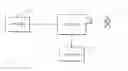
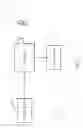
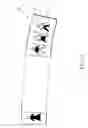
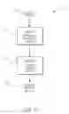
Sources:
- United States Patent and Trademark Office - verify current appl. status at the USPTO↗
Similar patent applications:
- » 20210342495
Garment Creation System, Method and Apparatus - » 20190008226
Method and System for Interactive Creation of Garments - » 20180168256
BODY-PERCEPTION ENHANCING STRIPED GARMENT AND SYSTEMS AND METHODS FOR CREATION THEREOF - » 20180215132
GARMENT OR SUBSTRATE AND SYSTEMS AND METHODS FOR CREATION THEREOF - » 20220292562
System and a method for providing an optimized online garment creation platform - » 20230252747
System and method for three dimensional creation of a virtual garment and simulating use of the virtual garment on an avatar of an end user - » 20250239039
SYSTEM AND METHOD FOR THREE DIMENSIONAL CREATION OF A VIRTUAL GARMENT AND SIMULATING USE OF THE VIRTUAL GARMENT ON AN AVATAR OF AN END USER - » 20180255853
SYSTEM OF PRODUCTION, MEASUREMENT, COMBINATION AND SIZES OF FABRIC, GARMENTS AND BAGS AIMING AT THEIR CREATION, READJUSTMENT AND COMPLETION BY ANY PERSON INDIVIDUALLY.
Recent applications in this class:
- » 20250278525 2025-09-04
CRAM VALIDATION USING AN EXTERNAL DEVICE - » 20250245388 2025-07-31
CONTROL DEVICE, MEMORY DEVICE AND DATA STORAGE SYSTEM - » 20250232067 2025-07-17
CRYPTOGRAPHIC KEY MANAGEMENT - » 20250181780 2025-06-05
SEMICONDUCTOR DEVICE WITH SELF-LOCK SECURITY AND ASSOCIATED METHODS AND SYSTEMS - » 20250148133 2025-05-08
SECURITY MANAGEMENT OF FERROELECTRIC MEMORY DEVICE - » 20250139302 2025-05-01
HARDWARE PROTECTION OF INLINE CRYPTOGRAPHIC PROCESSOR - » 20250124176 2025-04-17
KEY MANAGEMENT METHOD, DATA PROTECTION METHOD, SYSTEM, CHIP, AND COMPUTER DEVICE - » 20250117525 2025-04-10
ENCRYPTION DEVICE AND METHOD THEREOF UTILIZING WRITE LOCK, KEY LOCK, AND DIGEST INFORMATION TO INCREASE SECURITY - » 20250094649 2025-03-20
SAFETY AND SECURITY FOR MEMORY - » 20250094648 2025-03-20
MEMORY SYSTEM AND METHOD FOR VERIFYING SAFETY
Recent applications for this Assignee:
- » 20120141040 2012-06-07
Method of compressing sequence of strokes - » 20120140280 2012-06-07
Electronically transmitted document delivery through interaction with printed document - » 20120118965 2012-05-17
Process for decoding coded data - » 20120111939 2012-05-10
Transaction recordal method - » 20120104089 2012-05-03
Electronic pen for interacting with substrate - » 20120083252 2012-04-05
Messaging via a coded business card and mobile telephone - » 20120062953 2012-03-15
Application for generating interactive document containing advertising material - » 20120057919 2012-03-08
Pen-shaped printing device - » 20120056003 2012-03-08
Substrate having coding pattern encoding Reed-Solomon symbols - » 20120044186 2012-02-23
Handheld display device having processor for rendering display output with real-time virtual transparency and form-filling option