Method for production of sandwich panels with zigzag corrugated core
US20070141376A1
2007-06-21
10/579,764
2003-11-20
✅ Patent granted
US 7,814,658 B2
2010-10-19
WO; PCT/RU03/00512; 20031120
WO; WO2005/049247; 20050602
David P Bryant | Christopher Besler
2026-08-02
Abstract:
The invention can be defined in its most general form as a method for production of sandwich panels with zigzag corrugated core (2) from sheet material used in aircraft construction, shipbuilding, and other branches of industry. With the aim to improve the quality and ease of sheet blank folding into the 3-D relief structure in the sheet blank at locations of crimp zigzag lines (4) protrusions and recesses the holes are punched with the diameter not less than the sheet blank bending radius.
Inventors:
- Niaz Irekovich Akishev 8 🇷🇺 Kazan, Russian Federation
- Ildus Muhametgaleevich Zakirov 8 🇷🇺 Kazan, Russian Federation
- Alexandr Vladimirovich Nikitin 8 🇷🇺 Kazan, Russian Federation
- Niaz Irekovich Askishev 1 🇷🇺 Kazan, Russian Federation
Assignee:
- AIRBUS 12 🇫🇷 Blagnac Cedex, France
- OTKRYTOE AKTSIONERNOE OBSCHESTVO... 4 🇷🇺 Kazan, Russian Federation
- Otkrytoe Aktsionernoe Obschestvo “Kazansky Nauchno-Isledovatelsky Institut Aviatsionnoi Tekhnologii” 6 🇷🇺 Kazan, Russian Federation
Interested in similar patents?
Get notified when new applications in this technology area are published.
Classification:
B32B3/28 » CPC main
Layered products comprising a layer with external or internal discontinuities or unevennesses, or a layer of non-planar form ; Layered products having particular features of form characterised by a particular shape of the outline of the cross-section of a continuous layer; characterised by a layer with cavities or internal voids ; characterised by an apertured layer characterised by a layer comprising a deformed thin sheet, i.e. the layer having its entire thickness deformed out of the plane , e.g. corrugated, crumpled
B21D47/00 » CPC further
Processing sheet metal or metal tubes, or processing metal profiles according to any of groups - , in the manufacture of finished or semi-finished articles
B21D47/00 » CPC further
Making rigid structural elements or units, e.g. honeycomb structures
B32B2250/40 » CPC further
Layers arrangement Symmetrical or sandwich layers, e.g. ABA, ABCBA, ABCCBA
B32B2605/12 » CPC further
Vehicles Ships
B32B2605/18 » CPC further
Vehicles Aircraft
Y10T29/49623 » CPC further
Metal working; Method of mechanical manufacture; Structural member making Static structure, e.g., a building component
Y10T29/49627 » CPC further
Metal working; Method of mechanical manufacture; Structural member making; Static structure, e.g., a building component; Openwork, e.g., a truss, joist, frame, lattice-type or box beam Frame component
Y10T29/49629 » CPC further
Metal working; Method of mechanical manufacture; Structural member making; Static structure, e.g., a building component Panel
Y10T29/49995 » CPC further
Metal working; Method of mechanical manufacture Shaping one-piece blank by removing material
Y10T428/1234 » CPC further
Stock material or miscellaneous articles; All metal or with adjacent metals Honeycomb, or with grain orientation or elongated elements in defined angular relationship in respective components [e.g., parallel, inter- secting, etc.]
B32B3/12 IPC
Layered products comprising a layer with external or internal discontinuities or unevennesses, or a layer of non-planar form ; Layered products having particular features of form characterised by a discontinuous layer, i.e. formed of separate pieces of material characterised by a layer of regularly- arranged cells, e.g. a honeycomb structure
B21D39/00 IPC
Application of procedures in order to connect objects or parts, e.g. coating with sheet metal otherwise than by plating ; Tube expanders
B32B3/00 IPC
Layered products comprising a layer with external or internal discontinuities or unevennesses, or a layer of non-planar form ; Layered products having particular features of form
Description
TECHNICAL FIELDOur invention can be defined in its most general form as a method for production of sandwich panels with zigzag corrugated core from sheet material used in aircraft construction, shipbuilding, and other branches of industry.
BACKGROUND ARTThe method for production of sandwich panels with zigzag corrugated core including separate shaping of core layer and outer skins while core is produced by means of sheet blank bending along the zigzag lines of protrusions and recesses with the use of the marking-out, is taken as a prototype (Inventors' certificate no. 1,785,154 USSR, Int. Cl. B 23 K 20/00, Method for curvilinear sandwich panel with zigzag corrugated core production, Bulletin no. 28 of 30.07.93).
The short-coming of herein-presented method is in raise of material due to the stretching out effect in nodal zones. This effect occurs when shaping corrugated core in its nodal zones where at least four ridges of folded structure converge and a simultaneous bending in two planes takes place. It results in panel strength deterioration due to the point contact between the core and the skins since they interconnect only in nodal zones rather than along the lines of protrusions and recesses. In addition, the conditions of blank material deformation are least favorable due to necessity of applying considerable efforts when shaping; it results in concentration of stresses at this very zones and adversely affects the core-skin connection strength.
DISCLOSURE OF INVENTIONOur invention has for its object to improve the conditions of core shaping owing to elimination of bending zones in two planes and to increase the core-skin connection strength.
The technical result attained by our invention is the improvement of panels with folded structure core production quality.
The herein-presented technical result is attained by that in the known method for production of sandwich panel with zigzag corrugated core including separate shaping of the outer skins and the core and their further connection while the prescribed crimp profile is obtained by sheet blank bending along the marked-out on the development zigzag lines,—according to the technical solution: in the sheet blank of zigzag corrugated core development at the points of bending lines intersections the holes are punched with the diameter equal to dh≧Rb, where Rb is the maximum sheet blank bending radius.
The undertaken by the applicant state of the art analysis shows that there are no analogs characterized by the combination of the features identical to those of the invention. Therefore, the claimed technical solution satisfies the “novelty” condition of patentability.
The results of retrieval for the known solutions in the given area with the aim to reveal the features identical with distinctions of the claimed technical solution show that its features do not result from the state of the art. From the defined state of the art the applicant managed to reveal no influence of the specified essential features upon the attainment of the stated technical result. The claimed technology, therefore, satisfies the “inventive step” condition of patentability.
BRIEF DESCRIPTION OF DRAWINGSThe FIGS. 1-4 present the essence of the invention:
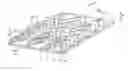
FIG. 1 is a general view of panel with zigzag core (the upper skin is not shown);
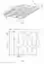
FIG. 2 shows a flat blank of core with the holes at the points of crimp zigzag line protrusions and recesses;
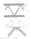
FIG. 3 is a sectional view A-A of FIG. 1;
FIG.4 is a scaled up view I of FIG. 1 sectional view A-A.
The FIGS. 1-4 present the following positions:
1 is the lower and the upper (not shown) skins; 2 is the corrugated core; 3 are the zigzag lines of crimp protrusions; 4 are the zigzag lines of crimp recesses;
5 are the saw-tooth lines; 6 is the core sheet blank; 7 are the holes at locations of zigzag and saw-tooth lines; 8 is the composite material with adhesive properties.
BEST MODE FOR CARRYING OUT THE INVENTIONOur method can be realized in the following way:
1) the outer and the inner skins 1 of the panel are produced;
2) the bending lines 3, 4, and 5 are marked-out on the core 2 sheet blank 6; i5 the parameters and relative position of bending lines 3, 4, and 5 are related by core 2 design parameters:
Ld=f(H,L); Vd=f(V,Ld); Sd=f(V,S,H,L), where
H is the height of zigzag crimp, V is the amplitude of zigzag lines, 2S is the step between zigzag lines, 2L is the step between saw-tooth lines, having the development dimensions: 2Sd is the step between zigzag lines, Ld is the distance between zigzag lines, Vd is the amplitude of zigzag lines;
3) the holes 7 are punched in the blank at the points of intersections of saw-tooth 5 and zigzag 3 and 4 lines; the diameter of the holes 7 is equal to dh≧Rb, where Rb is the sheet blank bending radius at the points of intersections of saw-tooth 5 and zigzag 3 and 4 lines in the ready-made core 2;
4) the sheet blank 6 is shaped until the 3-D relief structure 2 is formed;
5) the obtained folded structure 2 is connected with the outer and inner skins 1, e.g. with the use of composite material 8 with adhesive properties.
INDUSTRIAL APPLICABILITYThe claimed method for production of sandwich panels with zigzag corrugated core can be used in industrial production of aircraft sandwich panels. Created on the basis of the claimed method equipment will allow to improve the zigzag corrugated core production quality and increase the sandwich panel strength.
Claims
1. The method for production of sandwich panels with zigzag corrugated core including separate shaping of the outer skins and the core and their further connection while the prescribed crimp profile is obtained by means of sheet blank bending along the marked-out on the core development zigzag lines is characterized by that in the sheet blank at the points of bending lines intersections the holes are punched with the diameter equal to dh≧Rb, where Rb is the maximum sheet blank bending radius.
Images & Drawings included:
Sources:
- United States Patent and Trademark Office - verify current appl. status at the USPTO↗
Recent applications in this class:
- » 20250187296 2025-06-12
WATER-STOP FILM - » 20250187295 2025-06-12
WINDOW AND MANUFACTURING METHOD THEREOF - » 20250091314 2025-03-20
Honeycomb Core Material - » 20250001721 2025-01-02
THERMOPLASTIC BAGS WITH ENHANCED DART IMPACT RESISTANCE - » 20240375373 2024-11-14
PREFORM PATCH AND METHOD OF SUBSEQUENT REINFORCEMENT OF A FIBRE COMPOSITE COMPONENT - » 20240326374 2024-10-03
METHOD FOR MANUFACTURING LAMINATE SHAPED TO HAVE IRREGULARITIES, LAMINATE FOR SHAPING IRREGULARITIES, AND LAMINATE SHAPED TO HAVE IRREGULARITIES - » 20240326373 2024-10-03
Hollow fusion panel made of a combination of new and recycled materials and producing method thereof - » 20240092054 2024-03-21
THERMOPLASTIC BAGS WITH COMPLEX STRETCH PATTERNS - » 20240042727 2024-02-08
THERMOPLASTIC BAGS WITH COMPLEX STRETCH PATTERNS - » 20240017520 2024-01-18
SHEET HAVING CLOSED CELL LAYER
Recent applications for this Assignee:
- » 20120068008 2012-03-22
Aircraft provided with a fuel cell system - » 20110210204 2011-09-01
Passenger seat system incorporating a multi-functional furniture unit, and an aircraft comprising such a system - » 20100243801 2010-09-30
Modular furniture for an aircraft - » 20090261200 2009-10-22
Aircraft fuselage comprising a space for work and storage at the rear thereof - » 20070184144 2007-08-09
Foldable mandrel for production of a single curvature folded core for a sandwich panel - » 20070184144 2007-08-09
Foldable mandrel for production of a single curvature folded core for a sandwich panel - » 20070182064 2007-08-09
Method for production of sandwich panel core from composites - » 20070182064 2007-08-09
Method for production of sandwich panel core from composites - » 20070182064 2007-08-09
Method for production of sandwich panel core from composites - » 20070148412 2007-06-28
Sandwich panel