Method and device for storing information
US20070143524A1
2007-06-21
10/556,610
2004-05-12
✅ Patent granted
US 7,755,997 B2
2010-07-13
WO; PCT/IB2004/050665; 20040512
WO; WO2004/102569; 20041125
Thang V Tran
2027-11-04
Abstract:
A method is described for writing data to an optical storage medium which comprises a storage space (10) with blocks having hardware addresses (HA), the storage space (10) comprising a pre-embossed area (20), the data to be written comprising data addresses (DA). According to the invention, data having data addresses DA=&Delta are stored in storage space blocks having hardware addresses HA=X+&Delta, wherein &Delta is an integer equal to 1 or more.
Inventors:
- Robert Albertus Brondijk 37 🇳🇱 Eindhoven, Netherlands
- Robert Albertus Brondjik 1 🇳🇱 Eindhoven, Netherlands
Assignee:
- Koninklijke Philips Electronics, N.V. 13,903 🇳🇱 Eindhoven, Netherlands
Interested in similar patents?
Get notified when new applications in this technology area are published.
Classification:
G11B27/3027 » CPC main
Editing; Indexing; Addressing; Timing or synchronising; Monitoring; Measuring tape travel; Indexing; Addressing; Timing or synchronising; Measuring tape travel by using information detectable on the record carrier by using information signals recorded by the same method as the main recording on the same track as the main recording used signal is digitally coded
G11B7/00745 » CPC further
Recording or reproducing by optical means, e.g. recording using a thermal beam of optical radiation , reproducing using an optical beam at lower power ; Record carriers therefor; Arrangement of the information on the record carrier, e.g. form of tracks, actual track shape, e.g. wobbled, or cross-section, e.g. v-shaped; Sequential information structures, e.g. sectoring or header formats within a track Sectoring or header formats within a track
G11B20/1217 » CPC further
Signal processing not specific to the method of recording or reproducing; Circuits therefor; Digital recording or reproducing; Formatting, e.g. arrangement of data block or words on the record carriers on discs
G11B27/24 » CPC further
Editing; Indexing; Addressing; Timing or synchronising; Monitoring; Measuring tape travel; Indexing; Addressing; Timing or synchronising; Measuring tape travel by using information detectable on the record carrier by sensing features on the record carrier other than the transducing track ; sensing signals or marks recorded by another method than the main recording
G11B2220/216 » CPC further
Record carriers by type; Disc-shaped record carriers characterised in that the disc is of read-only, rewritable, or recordable type; Recordable discs Rewritable discs
G11B2220/2562 » CPC further
Record carriers by type; Disc-shaped record carriers characterised in that the disc is based on a specific recording technology; Optical discs DVDs [digital versatile discs]; Digital video discs; MMCDs; HDCDs
G06F12/00 IPC
Accessing, addressing or allocating within memory systems or architectures
G06F3/06 IPC
Input arrangements for transferring data to be processed into a form capable of being handled by the computer; Output arrangements for transferring data from processing unit to output unit, e.g. interface arrangements Digital input from, or digital output to, record carriers, e.g. RAID, emulated record carriers or networked record carriers
G11B20/12 IPC
Signal processing not specific to the method of recording or reproducing; Circuits therefor; Digital recording or reproducing Formatting, e.g. arrangement of data block or words on the record carriers
G11B7/007 IPC
Recording or reproducing by optical means, e.g. recording using a thermal beam of optical radiation , reproducing using an optical beam at lower power ; Record carriers therefor Arrangement of the information on the record carrier, e.g. form of tracks, actual track shape, e.g. wobbled, or cross-section, e.g. v-shaped; Sequential information structures, e.g. sectoring or header formats within a track
Description
FIELD OF THE INVENTIONThe present invention relates in general to a method and device for writing information to an optical storage medium which comprises a pre-embossed storage portion. Particularly, but not exclusively, the present invention relates to a method and device for writing information to an optical storage disc, more particularly a DVD-RW disc, and the present invention will be explained below with reference to this example.
BACKGROUND OF THE INVENTIONOptical storage discs are commonly known to those skilled in the art. Optical discs may be of the read-only type, where information is recorded during manufacture, which information can only be read by a user. Optical storage discs may also be of a writable type, where information may be stored by a user. Such discs may be a read-once type, indicated as writable (R), but there are also storage discs on which information can be written many times, indicated as rewritable MW). In the case of DVD, a distinction is made between two formats, i.e. DVD-RW and DVD+RW. Since the technology of optical discs in general, the way in which information can be stored in an optical disc, and the way in which optical data can be read from an optical disc are commonly known, it is not necessary here to describe this technology in more detail.
As is commonly known, memory space is divided into blocks, each block having an identification or address, such that a reading apparatus knows which block it is reading.
In the case of RW-type discs, the storage space is physically present in the form of a groove (+RW) or pre-pits (-RW), the blocks are predefined, and the addresses are already allocated and coded in physical hardware features of the storage space. A DVD-ROM reader is not equipped to read this physical coding, and is therefore not capable of reading these addresses. Therefore, in order to facilitate a DVD-ROM reader to read addresses, the addresses are also incorporated in the data to be written.
In the following, the addresses incorporated in physical hardware features of the disc, such as the groove wobble (+RW) or the pre-pits (-RW), will be indicated as hardware addresses, whereas the addresses incorporated in the written data will be indicated as data addresses. Normally, the values of these addresses are identical.
The memory space of a disc is subdivided in lead-in, main data, and lead-out areas. The lead-in area involves a group of blocks at the beginning of the disc, containing information relating to the disc itself. This information includes parameters like disc structure, book type (an indication of the standard used), and header byte, the header byte containing bits indicating area type (lead-in/main data, lead-out/middle data), a bit indicating whether the disc is read-only or not, and a bit indicating the reflectivity of the disc.
The present inventor has found that the playability of a disc depends on the values of said parameters. In this case playability can be defined as the degree to which a disc can be read by a disc drive with little or no errors. The playability is low in a case in which many errors are generated during play-back.
The present invention aims to improve the playability of the storage medium. To this end, the present invention proposes to amend the values of said parameters such that the playability is increased, preferably such that the playability is maximal. In this respect, the present invention is based on the recognition that said parameters are for information purposes only, but do not actually change any setting of a disc drive.
DVD-RW type discs have a further problem in this respect, namely that the storage space portion where these parameters are stored is a pre-embossed area, i.e. an area which is not writeable. Of course, it is not possible to change the values of parameters stored in a non-writeable area.
It is an object of the present invention to provide a solution to this problem.
SUMMARY OF THE INVENTIONAccording to an important aspect of the present invention, the data addresses are not equal to the hardware addresses. In this respect, the present invention is based on the recognition that a reader apparatus, when reading a disc, only takes into account the data addresses and does not check whether or not the hardware addresses are identical to the data addresses.
Thus, according to the present invention, the data addresses corresponding to said parameters can be shifted to a rewriteable area, so that it is possible to change the values of the parameters as desired.
BRIEF DESCRIPTION OF THE DRAWINGSThese and other aspects, features, and advantages of the present invention will be further explained by the following description of the present invention with reference to the drawings, in which same reference numerals indicate same or similar parts, and in which:
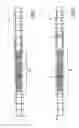
FIG. 1 schematically illustrates the storage space of a disc;
FIG. 2 schematically illustrates the storage space of a disc in which the data shift method of the present invention has been incorporated;
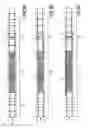
FIGS. 3A-C are Figures comparable to FIG. 2, illustrating details of different embodiments of the invention.
DESCRIPTION OF TIE INVENTIONFIG. 1 schematically illustrates the storage space 10 of a DVD-RW disc as a continuous ribbon. Below the storage space 10, hardware addresses HA are indicated as consecutive numbers 0, 1, 2, etc. Above the storage space 10, data addresses DA are also indicated as consecutive numbers 0, 1, 2, etc. In this case, data addresses DA are identical to hardware addresses HA. Some of the addresses correspond to a pre-embossed area 20, which contains N blocks (ECC blocks). In the example of FIG. 1, said pre-embossed area 20 contains 192 blocks (N=192), as is the case in the DVD format. The addresses in this pre-embossed area 20 are indicated as ranging from a first address A to a last address A+192. In the case of DVD, these 192 blocks of the pre-embossed area 20 are mutually identical; however, this is not essential for implementing the present invention.
Said blocks of the pre-embossed area 20 contain at least one information byte with disc parameters, as was noted above. If the blocks of the pre-embossed area 20 are mutually identical, as is the case in DVD, each block of the pre-embossed area 20 contains such an information byte. However, for explaining the present invention, it suffices if only one block contains such an information byte, which is referenced 11 in FIG. 1. Therefore, only the block with address A+2 is shown to contain an information byte 11 by way of example in FIG. 1.
Normally data can be written in the blocks in any manner desired in the case of writeable storage media (R; RW). However, the pre-embossed area 20 is non-writeable, as is shown by the hatching of the storage portion of area 20. The information byte 11 is located in a block within said pre-embossed area 20, so its contents cannot be amended as desired.
FIG. 2 is a schematic drawing comparable to FIG. 1, for illustrating a storage space 10 in which the data shift method of the present invention has been incorporated. In this example, blocks having data addresses X are written into storage space blocks having hardware addresses X+Δ. Or, worded differently, data written in a storage space block having a hardware address Y has a data address Y−Δ. Thus, a shift of Δ blocks is achieved, Δ being one or more. In this example, Δ is chosen to be equal to N (=192).
It is noted that in FIG. 2, merely for sake of illustration, the data addresses having a lower address value than said data address A are shown with a successively decreasing value, i.e. A−1, A−2, . . . A−192. It should be realized, however that the blocks in the pre-embossed area 20 cannot have data addresses deviating from the hardware addresses, because the addresses of this storage area can not be changed.
The value of the shift parameter A is chosen such that the relevant information bytes obtain a storage location outside the pre-embossed area 20, i.e. in the rewritable portion of the storage space 10. In the example of FIG. 2, said information byte (denoted 11′) is now written in a block having hardware address A+194, i.e. outside the pre-embossed area 20.
In some cases, it may be sufficient if Δ is smaller than N, as long as Δ is sufficiently great to ensure that one block-of-interest (DA=A+2) is shifted to a storage location (HA=A+194) outside said pre-embossed area 20. Preferably, the value of the shift parameter Δ is chosen such that all data addresses corresponding to hardware addresses within said pre-embossed area 20 are shifted to storage locations outside said pre-embossed area 20, i.e. Δ≧N. In the example of FIG. 2, Δ is equal to N, so that the first block within said pre-embossed area 20 (DA=A) is shifted to the block directly adjacent the last block within said pre-embossed area 20 (i.e. HA=A+192). However, it is preferred that some margin is created between the uppermost address of the pre-embossed area 20 (i.e. HA=A+191) and the new location of the lowermost address of the pre-embossed area 20 (i.e. DA=A); this margin preferably corresponds to a radial distance of the order of about 0.05 mm.
The present invention proposes three possible variations of the data shift method. In a first embodiment illustrated in FIG. 3A, the storage space portion 21 containing all addresses lower than the pre-embossed area 20 is ignored, i.e. no information is written in this portion. In FIG. 3A, this is illustrated by the fact that the blocks in this portion 21 have no data addresses. Furthermore, no information is written in said pre-embossed area 20 in this embodiment. In other words, information is only written into the storage space portion 23 containing addresses higher than the pre-embossed area 20 (i.e. HA>A+191). It is noted that FIG. 3A correctly shows that the data addresses DA are identical to the hardware addresses HA in the pre-embossed area 20.
In a second embodiment illustrated in FIG. 3B, said portions 21 and 23 are written, but said pre-embossed area 20 is not written. Thus, in the example of FIG. 3B, -information can be written in blocks having hardware addresses HA<A. In FIG. 3B, this is illustrated by the fact that the blocks in this portion 21 have data addresses i, i+1, i+2, etc.
In the third embodiment illustrated in FIG. 3C, a write procedure is performed in respect of the pre-embossed area 20 as well as said areas 21 and 23 below and above the pre-embossed area 20. As in the second embodiment, information can now be written in the blocks having hardware address HA<A. However, the write process with respect to the pre-embossed area 20 will result in the data of the pre-embossed area 20 being destroyed, illustrated as a hatched portion in respect of the data addresses.
An advantage of the third embodiment of FIG. 3C is that the data-addressing of the storage space blocks is unambiguous. More particularly, it is effectively avoided that a read apparatus is capable of reading the pre-embossed area 20 at all. In the embodiments of FIGS. 3A and 3B, the data-addressing is not unambiguous. For instance, in the examples of FIGS. 3A and 3B, the block data address A+2 is present twice, once corresponding to HA=A+2 within the pre-embossed area 20, and a second time corresponding to HA=A+194 outside the pre-embossed area 20. Furthermore, in the example of FIG. 3B, block data address A−193 is present twice (HA=A−193 and HA=A−1), while there is an address discontinuity between HA=A−1 and HA=A (DA=A−193 and DA=A). In principle, a disc reader apparatus may consider such a situation to be an error situation which cannot be resolved.
Nevertheless, in all three embodiments illustrated in FIGS. 3A-C, disc reader apparatuses will be capable of reading the disc because they do not start at address 0 but they start at a certain radius which lies beyond the pre-embossed area 20. This radius is such that, even if tolerances are taken into account, an initial access of the disc reader apparatus is always beyond the pre-embossed area 20. For reading info byte 11, the disc reader will then approach the corresponding data address DA=A+2 from above, and will settle at data address DA=A+2 corresponding to hardware address HA=A+194, thus effectively reading byte 11′ outside the pre-embossed area 20 instead of the original byte 11 inside the pre-embossed area 20.
A disc writing apparatus, when writing the data to storage space 10, especially when writing the information bytes 11′ in data address DA=A+2, may select suitable values for the information bytes 11′, deviating from the values of the original information bytes 11 in hardware address HA=A+2. The information bytes as written may have information values selected for optimum playability of the same apparatus during reading. These values may be stored in a memory of the drive and, when writing the data to storage space 10, the disc drive may read said values from this memory.
It is also possible that the disc is to be read by another apparatus, in which case the disc writing apparatus may be provided with input means for inputting user-determined values to be written as information bytes 11.
If the user does not know the optimum values for the read apparatus, it may be necessary to determine the optimum value through trial and error, i.e. by setting different values for the information bytes 11′, each time determining the playability, and setting said disc information bytes 11′ to those respective values which have been determined as providing the best playability.
It should be clear to those skilled in the art that the present invention is not limited to the exemplary embodiments discussed above, but that various variations and modifications are possible within the protective scope of the invention as defined in the appended claims.
While the invention has been explained by describing that the information of one single byte 11 in one block A+2 can be amended, it should be clear that the user may write any suitable data in the entire block A+2 for improving playability. Furthermore, although the present invention basically allows for different information to be written in the shifted blocks (i.e. HA=A+192 to HA=A+191+192), it is preferred that the same information is written in all of these blocks.
It is further to be understood that one or more of the functional aspects of the invention may be implemented in hardware, but it is also possible that one or more of these functional aspects are implemented in software.
Claims
1. Method of writing data to an optical storage medium which comprises a storage space (10) with blocks having hardware addresses (HA), the storage space (10) comprising a pre-embossed area (20), the data to be written comprising data addresses (DA);
wherein data having data addresses DA=X are stored in storage space blocks having hardware addresses HA=X+Δ, wherein Δ is an integer at least equal to 1, preferably equal to 192 or more.
2. Method according to claim 1, wherein the data to be written comprise at least one lead-in block comprising at least one byte (11) which contains information relating to the disc itself, said at least one lead-in block having a data address DA=X corresponding to a hardware address HA=X within said pre-embossed area (20); and
wherein Δ is selected such that said at least one lead-in block is stored in a storage space block having a hardware address HA=X+A outside said pre-embossed area (20).
3. Method according to claim 2, wherein Δ is selected such that the radial distance between a block having hardware address HA=X within said pre-embossed area (20) and a block having hardware address HA=X+Δ outside said pre-embossed area (20) is less than 0.2 mm, preferably less than 0.1 mm.
4. Method according to claim 2, wherein Δ is selected such that substantially all data blocks having data addresses DA=X corresponding to hardware addresses HA=X within said pre-embossed area (20) are stored in storage space blocks having hardware addresses HA=X+Δ outside said pre-embossed area (20).
5. Method according to claim 2, wherein Δ is selected such that the radial distance between the last block (HA=A+191) within said pre-embossed area (20) and the new location of the lowest address of the pre-embossed area 20 (i.e. HA=A+Δ) is more than zero, preferably being of the order of about 0.05 mm.
6. Method according to claim 2, wherein the data to be written into the shifted version of said disc information byte (11′) (HA=A+194) are selected such as to improve disc playability.
7. Method according to claim 2, wherein the data to be written into the entire shifted version of said lead-in block (HA=A+194) are selected such as to improve disc playability.
8. Method according to claim 6, wherein the same data are written into all blocks (HA=A+Δ to HA=A+191+Δ) having data addresses (DA=A to DA=A+191) corresponding to hardware addresses (HA=A to HA=A+191) within said pre-embossed area (20).
9. Method according to claim 6, wherein the value of said disc information byte (11′) is inputted by a user.
10. Method according to claim 6, comprising the steps of:
selecting a first value for said disc information byte (11) and writing it to disc;
determining the playability of the disc with said disc information byte (11′) having its first value;
selecting a second value for said disc information byte (11′) and writing it to disc;
determining the playability of the disc with said disc information byte (11′) having its second value;
determining which of said first and second values for said disc information byte (11′) provides better playability;
setting said disc information byte (11′) to that value which has been determined as providing better playability.
11. Method according to claim 2, wherein information is only written into a storage space (23) having hardware addresses higher than said pre-embossed area (20).
12. Method according to claim 2, wherein information is only written into a storage space (23) having hardware addresses higher than said pre-embossed area (20) and into a storage space (21) having hardware addresses lower than said pre-embossed area (20).
13. Method according to claim 2, wherein information is also written into said pre-embossed area (20).
14. Disc drive apparatus capable of writing information to an optical storage medium which comprises a storage space (10) with blocks having hardware addresses (HA), the storage space (10) comprising a pre-embossed area (20), the data to be written comprising data addresses (DA);
the apparatus being designed to perform a method according to claim 1.
15. Disc drive apparatus according to claim 14, comprising input means for inputting user-determined values to be written as information bytes (11′).
16. Optical storage medium comprising a storage space (10) with blocks having hardware addresses (HA), the storage space (10) comprising a pre-embossed area (20);
the storage medium containing data written in said storage space (10), the data comprising data addresses (DA);
wherein, at least in a portion (23) of said storage space (10) outside said pre-embossed area (20), a block having hardware address HA=Y contains data having data address DA=Y−Δ, wherein Δ is an integer equal to 1 or more, preferably equal to 192 or more.
17. Optical storage medium according to claim 16, wherein blocks having hardware addresses HA=Y≧A+192, higher than said pre-embossed area (20), contain data having data addresses DA=Y−Δ, while blocks having hardware addresses HA=Y<A, lower than said pre-embossed area (20), contain no data.
18. Optical storage medium according to claim 16, wherein blocks having hardware addresses HA=Y≧A+192, higher than said pre-embossed area (20), contain data having data addresses DA=Y−Δ, while blocks having hardware addresses HA=Y<A, lower than said pre-embossed area (20), contain data having data addresses DA=Y.
19. Optical storage medium according to claim 16, wherein blocks having hardware addresses HA=Y≧Δ+19, higher than said pre-embossed area (20), contain data having data addresses DA=Y−Δ, while blocks having hardware addresses HA=Y<A, lower than said pre-embossed area (20), also contain data having data addresses DA=Y−Δ.
20. Optical storage medium according to claim 19, wherein the data of blocks within said pre-embossed area (20) are destroyed.
21. Optical storage medium according to claim 16, wherein the radial distance between a block having hardware address HA=X inside said pre-embossed area (20) and the corresponding shifted block having data address DA=X (HA=X+Δ) outside said pre-embossed area (20) is less than 0.2 mm, preferably less than 0.1 mm.
22. Optical storage medium according to claim 16, wherein the radial distance between the last block (HA=A+191) within said pre-embossed area (20) and the shifted block corresponding to the lowest address of the pre-embossed area 20 (HA=A+Δ) is more than zero, preferably being of the order of about 0.05 mm.
23. Optical storage medium according to claim 16, wherein a block having hardware address HA=X within said pre-embossed area (20) contains first data, and wherein a block having data address DA=X (HA=X+Δ) contains second data differing from said first data.
Images & Drawings included:
Sources:
- United States Patent and Trademark Office - verify current appl. status at the USPTO↗
Similar patent applications:
- » 20070127735
Information retrieving method, information retrieving device, information storing method and information storage device - » 9830222
Information retrieving method, information retrieving device, information storing method and information storage device - » 20050146806
Information storing device and method for controlling same to record/reproduce information by selecting one of working modes - » 20110205664
Information storing device and method for controlling same to record/reproduce information by selecting one of working modes - » 10406007
Information storing device and method for controlling same to record/reproduce information by selecting one of working modes - » 20190118736
Onboard relay device, information processing method, storage medium storing program, relay device, and information processing system - » 10364746
Error detecting method and device, information storing and reproducing device and magnetic disk drive - » 20170235655
Information processing device and method of storing failure information - » 20160354691
Information processing device, information processing method, program, information storing medium, information processing system, and management device - » 20240330820
INFORMATION PROCESSING METHOD, STORAGE MEDIUM STORING INFORMATION PROCESSING PROGRAM, DATA PROCESSING SYSTEM, DATA DISPLAY DEVICE, INFORMATION ACCUMULATION METHOD, STORAGE MEDIUM STORING INFORMATION ACCUMULATION PROGRAM, AND DATA ACCUMULATION SYSTEM
Recent applications in this class:
- » 20230267966 2023-08-24
Cartridge including tape-shaped magnetic recording medium - » 20230123545 2023-04-20
Multimedia distribution system - » 20220406340 2022-12-22
Cartridge including tape-shaped magnetic recording medium - » 20220076709 2022-03-10
Multimedia distribution system - » 20220051697 2022-02-17
Multimedia distribution system - » 20210390984 2021-12-16
Cartridge including tape-shaped magnetic recording medium - » 20200321033 2020-10-08
Cartridge - » 20200321032 2020-10-08
Magnetic recording medium - » 20200251147 2020-08-06
Movie advertising playback systems and methods - » 20200176030 2020-06-04
Systems and methods for detecting moments within videos
Recent applications for this Assignee:
- » 20210337645 2021-10-28
METHOD AND ADJUSTMENT SYSTEM FOR ADJUSTING SUPPLY POWERS FOR SOURCES OF ARTIFICIAL LIGHT - » 20210290972 2021-09-23
BODY ILLUMINATION SYSTEM USING BLUE LIGHT - » 20190191921 2019-06-27
METHOD AND SYSTEM FOR BREWING INGREDIENTS IN A SOLVENT, APPARATUS USING SAID SYSTEM - » 20170325686 2017-11-16
System and method for extracting physiological information from remotely detected electromagnetic radiation - » 20150380899 2015-12-31
Eye-safe laser-based lighting - » 20150305720 2015-10-29
Ultrasonic synthetic transmit focusing with motion compensation - » 20150189712 2015-07-02
LED lighting arrangement and method of controlling a LED lighting arrangement - » 20150181667 2015-06-25
Driver circuit between fluorescent ballast and LED - » 20150171273 2015-06-18
Solid state light emitting devices based on crystallographically relaxed structures - » 20150146407 2015-05-28
Lighting device having a remote wavelength converting layer