Cover-handle assembly for a kitchen vessel
US20070145054A1
2007-06-28
11/604,446
2006-11-27
✅ Patent granted
US 7,789,259 B2
2010-09-07
-
-
Anthony Stashick | Kareen Rush
2028-10-07
Abstract:
A cover-handle assembly for a kitchen vessel comprises a cover element having an outer central support element swingably housing plate gripping means which, in a rest position thereof, adjoin the surface of the cover element and, in a use position thereof, project with a slanted attitude from the cover element surface.
Assignee:
- Ballarini Paolo & Fieli S.p.A. 1 🇮🇹 Mantovano, Italy
Interested in similar patents?
Get notified when new applications in this technology area are published.
Classification:
A47J45/063 » CPC main
Devices for fastening or gripping kitchen utensils or crockery; Handles for hollow-ware articles Knobs, e.g. for lids
B65D25/28 IPC
Details of other kinds or types of rigid or semi-rigid containers Handles
B65D45/00 IPC
Clamping or other pressure-applying devices for securing or retaining closure members
B65D51/12 IPC
Closures not otherwise provided for; Loosely-engaging lids or covers for jars, cans, or like containers for liquids without means for effecting sealing of container Flexible non-elastic covers
B65D41/16 IPC
Caps, e.g. crown caps or crown seals, i.e. members having parts arranged for engagement with the external periphery of a neck or wall defining a pouring opening or discharge aperture; Protective cap-like covers for closure members, e.g. decorative covers of metal foil or paper; Caps or cap-like covers without lines of weakness, tearing strips, tags, or like opening or removal devices Snap-on caps or cap-like covers
B65D25/10 IPC
Details of other kinds or types of rigid or semi-rigid containers; Internal fittings Devices to locate articles in containers
Description
BACKGROUND OF THE INVENTIONThe invention relates to a cover-handle assembly for a kitchen vessel.
A kitchen vessel cover including a projecting gripping knob arranged at the center of the cover, is already known in the prior art.
Such a provision of the central projecting gripping knob represents a drawback since the gripping knob, projecting from the cover, requires a comparatively large space for arranging, for example, the cover in a washing dish machine or in a drawer of a kitchen furniture piece.
In further prior kitchen vessel covers, the cover knobs or handles radially project from the cover circumference.
However, also this cover embodiment requires a comparatively large space, both as the kitchen vessel is arranged on a heating source, and as the kitchen vessel cover is arranged in a wash dish machine or stored in a drawer.
SUMMARY OF THE INVENTIONAccordingly, the aim of the invention is to overcome the above mentioned drawbacks of the prior art, by providing a kitchen vessel cover which, in a non-use position thereof, does not comprise any gripping members projecting from the cover. The above mentioned aim is achieved by a kitchen vessel cover-handle assembly comprising a cover having an outer central supporting body swingably supporting plate gripping means which, in a rest position thereof, adjoin a surface of the cover and which, in a use position thereof, project with a slanted attitude from said surface of said cover.
Advantageously, each said gripping means or element comprises a bulging, concave, surface, which, in a rest position thereof, is substantially parallel to the cover surface.
BRIEF DESCRIPTION OF THE DRAWINGSFurther advantages of the invention will become more apparent hereinafter from the following disclosure, the dependent claims and the accompanying drawings.
The subject matter of the present invention will be disclosed in a more detailed manner hereinafter and shown in the accompanying drawings, where:
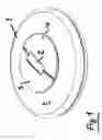
FIG. 1 is a top perspective view of the kitchen vessel cover with its gripping elements arranged in a rest position thereof;
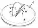
FIG. 2 is a further top perspective view of the cover with the gripping elements thereof in a use position;
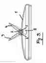
FIG. 3 is a cross-sectional view of the cover and with the gripping elements in a use position thereof;
FIG. 4 is a further cross-sectional view of the cover, the gripping elements and gripping element supporting means.
DESCRIPTION OF THE PREFERRED EMBODIMENTWith reference to FIG. 1, the cover 1, which may have a circular, square, rectangular or oval configuration, comprises, at the center thereof, a substantially flat supporting body 2. To said supporting body 2 gripping elements 3, and 4 are pivotably coupled. As shown, each gripping element 3 and 4 is formed by a semicircular plate.
It should be however apparent that said gripping elements 3 and 4 may have any other desired geometrical configuration. As shown in FIG. 1, the two gripping elements 3 and 4, in a rest position thereof, adjoin the surface 5 of the cover 1, thereby they will not practically occupy any useful space above the surface 5 of the cover.
Actually, said gripping elements will occupy, either in an axial or in a vertical direction, a space which is slightly larger than their thickness.
FIG. 2 shows the cover 1 and gripping elements 3 and 4 oscillated about swinging shafts or pivot pins engaged in the supporting body 2.
The driving mechanism, which will be disclosed in a more detailed manner hereinafter, is designed to allow to arrange the gripping elements 3 and 4 at a position slanted or inclined with respect to a vertical plane (see the arrows f).
FIG. 3 is a cross-sectional view showing a cross section of the cover 1.
At a central portion of the cover a supporting body or element 2, for example of a flat parallelepipedal shape, is arranged for swingably housing, through two pivot pins 6 and 7, the gripping elements 3 and 4 forming the subject novel handle. The supporting body 2 is operatively coupled to a drive mechanism 8, fixedly arranged inside the cover 1 and which will be disclosed in a more detailed manner hereinafter.
As shown in FIG. 4, the two gripping elements or handles 3 and 4 of the cover are coupled through cross pins (see FIG. 3) to the supporting body 2, said supporting body 2 comprising a supporting element stem 9 passing through the wall of the cover 1 and being engaged in a cavity of a cup element 10 fixed to said stem by a clamping screw 11.
Between the inside face of the cover 1 and floor of the cup element or body 10 a resilient means, for example a spring 12 or a silicone body, tending to drive the body of the supporting body 2 permanently toward the surface 5 of the cover 1, is arranged.
Said spring 12 is so designed as to tend to hold the gripping elements or handles 3 and 4 in their rest position joining the cover surface 5 (see FIG. 1).
To bring the two handles 3 and 4 to their use position, as shown in FIG. 2, said handles are upward oscillated about the pivot pins 6 and 7 and against the counter-biasing of the spring 12.
Claims
1. A cover-handle assembly for a kitchen vessel, characterized in that said cover-handle assembly comprises a cover (1) having an outer central supporting body (2) swingably supporting plate gripping means (3, 4) which, in a rest position thereof (FIG. 1) adjoin a surface (5) of the cover (1) and, in a use position thereof (FIG. 2) project with an inclined attitude from the surface of the cover.
2. A cover-handle assembly, according to claim 1, characterized in that said plate elements (3, 4) have a semicircular configuration.
3. A cover-handle assembly, according to claim 1, characterized in that said plate elements (3, 4) are swingably coupled to said supporting body (2) which, by coupling pins (6, 7), is made rigid with said cover (1).
4. A cover-handle assembly, according to claim 1, characterized in that said supporting body (2) is operatively coupled to a driving mechanism (8) arranged on an inside surface of said cover (1).
5. A cover-handle assembly, according to claim 1, characterized in that said supporting body (2) comprises a supporting body stem (9) passing through the wall of the cover (1), said stem (9) being engaged in a cavity of a cup element (10) clamped to said stem (9) by a clamping screw (11)
6. A cover-handle assembly, according to claim 1, characterized in that between the inner surface of the cover (1) and a floor of said cup body (10) a spring means (12) for permanently urging said supporting body (2) toward said surface (5) of the cover (1), is arranged.
7. A cover-handle assembly, according to claim 6, characterized in that said spring means (12) is (are) so designed as to hold said handles (3, 4) at a rest position thereof joining said surface (5) of the cover and that, with said handles (3, 4) raised and in a use position thereof, said spring means (12) clamp(s) said handles (3, 4) in a slanted and upward oriented position.
8. A cover-handle assembly, according to claim 1, characterized in that said supporting body (2) is so designed as to lock said gripping means in a preset slanted position thereof.
Images & Drawings included:


Sources:
- United States Patent and Trademark Office - verify current appl. status at the USPTO↗
Recent applications in this class:
- » 20230072062 2023-03-09
Collapsible handle for cookware lids - » 20210030211 2021-02-04
STACKABLE FRYING PANS AND SAUCEPANS - » 20090020531 2009-01-22
Cooking appliance lid