Bracket fixing structure
US20070145228A1
2007-06-28
11/640,874
2006-12-19
✅ Patent granted
US 7,618,012 B2
2009-11-17
-
-
Amy J. Sterling
2026-12-19
Abstract:
A bracket concave portion of a bracket is inserted into a vehicular jig concave portion of a vehicular jig, and a washer is put on a face of the bracket through an elastic member on a side opposite from a contact face of the bracket contacting the vehicular jig. The bracket is fixed by inserting a screw into a washer screw hole, an elastic member screw hole, a bracket screw hole and an attachment member screw hole from a side of the washer opposite from a contact face of the washer contacting the bracket. Thus, vibration of the bracket can be damped economically.
Assignee:
- DENSO CORPORATION 9,454 🇯🇵 Kariya-city, Japan
- DENSO CORPORATION 13,436 🇯🇵 Kariya, Japan
Interested in similar patents?
Get notified when new applications in this technology area are published.
Classification:
F16B5/0241 » CPC main
Joining sheets or plates, e.g. panels, to one another or to strips or bars parallel to them by means of fastening members using screw-thread with the possibility for the connection to absorb deformation, e.g. thermal or vibrational
B60R11/02 » CPC further
Arrangements for holding or mounting articles, not otherwise provided for for radio sets, television sets, telephones, or the like; Arrangement of controls thereof
F16M5/00 IPC
Engine beds, i.e. means for supporting engines or machines on foundations
F16M7/00 IPC
Details of attaching or adjusting engine beds, frames, or supporting-legs on foundation or base; Attaching non-moving engine parts, e.g. cylinder blocks
F16M1/00 IPC
Frames or casings of engines, machines or apparatus; Frames serving as machinery beds
F16M11/00 IPC
Stands or trestles as supports for apparatus or articles placed thereon Stands for scientific apparatus such as gravitational force meters
F16M3/00 IPC
Portable or wheeled frames or beds, e.g. for emergency power-supply aggregates, compressor sets
F16M9/00 IPC
Special layout of foundations with respect to machinery to be supported
A47B96/06 IPC
Details of cabinets, racks or shelf units not covered by a single one of groups - ; General details of furniture Brackets or similar supporting means for cabinets, racks or shelves
A47G29/00 IPC
Supports, holders, or containers for household use, not provided for in groups - or
A47K1/00 IPC
Wash-stands; Appurtenances therefor
Description
CROSS REFERENCE TO RELATED APPLICATIONThis application is based on and incorporates herein by reference Japanese Patent Application No. 2005-375670 filed on Dec. 27, 2005.
BACKGROUND OF THE INVENTION1. Field of the Invention
The present invention relates to a fixing structure of a bracket. Specifically, the present invention relates to a fixing structure of a bracket used when a sensor unit or a motor is mounted to a vehicle through the bracket.
2. Description Of Related Art
There is a supporting bracket used under a situation that causes vibration, for example, as described in JP-A-H10-292844 as shown in FIG. 4. The supporting bracket 2 is used to mount a vibration generating body 4 such as a motor to an attachment part 3 such as a vehicle body. The supporting bracket 2 has damping panels 1 incorporating piezoelectric-crystal elements. The damping panel 1 has a controller for controlling distortion amounts of the piezoelectric-crystal elements.
The controller perceives deformation of the supporting bracket 2 due to the vibration with the piezoelectric-crystal elements and generates inner stress in the piezoelectric-crystal elements in a direction for restraining or promoting the deformation in accordance with the deformation amount of the supporting bracket 2. Thus, an apparent spring constant of the supporting bracket 2 can be freely changed to damp the vibration of the supporting bracket 2.
However, this technology requires the piezoelectric-crystal elements, the controller for controlling the distortion amounts of the piezoelectric-crystal elements and the like, increasing a cost.
SUMMARY OF THE INVENTIONIt is an object of the present invention to provide a fixing structure of a bracket capable of economically damping vibration of the bracket.
According to an aspect of the present invention, a bracket fixing structure includes a bracket, an attachment member, a screw and a washer. The attachment member is formed with an annular attachment member concave portion, an attachment member protruding portion surrounded by the attachment member concave portion, and an attachment member screw hole in the attachment member protruding portion. The bracket is formed with an annular bracket concave portion corresponding to the attachment member concave portion, a bracket protruding portion surrounded by the bracket concave portion, and a bracket screw hole in the bracket protruding portion. The washer is formed with a washer screw hole and a fixing portion extending at least from the bracket protruding portion to an outer periphery of the bracket concave portion. The bracket is fixed by inserting the bracket concave portion into the attachment member concave portion, by putting the washer on a face of the bracket opposite to a contact face of the bracket contacting the attachment member, and by inserting the screw into the washer screw hole, the bracket screw hole and the attachment member screw hole from a side of the washer opposite to a contact face of the washer contacting the bracket.
Thus, an area in which the bracket is fixed to the attachment member can be increased, so resonance frequency can be increased. As a result, vibration of the bracket can be damped economically. Moreover, by damping the vibration of the bracket, resonance fracture of the bracket can be inhibited.
BRIEF DESCRIPTION OF THE DRAWINGSFeatures and advantages of embodiments will be appreciated, as well as methods of operation and the function of the related parts, from a study of the following detailed description, the appended claims, and the drawings, all of which form a part of this application. In the drawings:
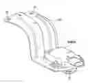
FIG. 1 is a sectional view showing a fixing structure of a bracket according to an example embodiment of the present invention;
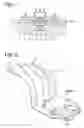
FIG. 2 is a schematic view showing the bracket according to the FIG. 1 embodiment;
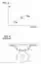
FIG. 3 is a graph showing a relationship between a fixing area and resonance frequency according to the FIG. 1 embodiment; and
FIG. 4 is a schematic view showing a supporting bracket of a prior art.
DETAILED DESCRIPTION OF EXAMPLE EMBODIMENTSReferring to FIG. 1, a fixing structure of a bracket 2 according to an example embodiment of the present invention is illustrated. The fixing structure of the bracket 2 according to the present embodiment includes an attachment member 10, the bracket 20, a washer 30, a screw 40, an elastic member 50 and the like.
In the present embodiment, the attachment member 10 is a vehicular jig. The vehicular jig 10 is a fixing jig used when the bracket 20 is fixed to a vehicle. As shown in FIG. 1, the vehicular jig 10 is formed with a vehicular jig concave portion 11 as a continuous annular concave portion, a vehicular jig protruding portion 12 surrounded by the vehicular jig concave portion 11, a vehicular jig screw hole 13 and the like. Alternatively, the attachment member 10 may be a vehicle body.
The bracket 20 is formed with a bracket concave portion 21 as a continuous annular concave portion corresponding to the vehicular jig concave portion 11, a bracket protruding portion 22 surrounded by the bracket concave portion 21, a bracket screw hole 23 in the bracket protruding portion 22 at a position corresponding to the vehicular jig screw hole 13 and the like. As shown in FIG. 2, a sensor unit, a motor or the like is fixed on a portion of the bracket 20 other than the portion fixed to the vehicular jig 10. The bracket concave portion 21 and the bracket protruding portion 22 are not shown in FIG. 2.
A top face of the bracket protruding portion 22 is spaced away from a plane defined by a rim of the bracket concave portion 21. Thus, contact between the washer 30 and the bracket 20 at the protruding portion 22 with a large normal force can be prevented. Since the protruding portion 22 of the bracket 20 is lowered compared to the plane defined by the rim of the bracket concave portion 21, a clearance is produced between the bracket 20 and the washer 30. In this case, there is a possibility that the screw 40 loosens. Therefore, the elastic member 50 should be preferably provided between the bracket protruding portion 22 and the washer 30.
Each of the vehicular jig concave portion 11 and the bracket concave portion 21 is formed in a shape having an opening wider than its bottom. A side wall face of each of the vehicular jig concave portion 11 and the bracket concave portion 21 is formed in a shape inclined from the bottom toward the opening. Thus, a contact area between the vehicular jig 10 and the bracket 20 is increased. The present invention is not limited to this structure. An object of the present invention can be attained also in the case where the wall faces of the vehicular jig concave portion 11 and the bracket concave portion 21 are not inclined.
The washer 30 is formed with a washer screw hole 33 at a position corresponding to the vehicular jig screw hole 13 and the bracket screw hole 23, a fixing portion 34 extending at least from the bracket protruding portion 22 to the outer periphery of the bracket concave portion 21 and the like.
In the case where the bracket 20 is fixed, vibration amplitude can be reduced by increasing resonance frequency of the bracket 20. Resonance fracture of the bracket 20 can be inhibited by increasing the resonance frequency over a fundamental frequency of a vibration source such as the engine of the vehicle. An area (fixing area) in which the bracket is fixed to the attachment member is one of factors deciding the resonance frequency f. As shown in FIG. 3, the resonance frequency f can be increased by increasing the fixing area.
Therefore, in the present embodiment, the bracket concave portion 21 is inserted into the vehicular jig concave portion 11, and the washer 30 is put on the face of the bracket 20 through the elastic member 50 on a side opposite from the contact face of the bracket 20 contacting the vehicular jig 10. In this state, the bracket 20 is fixed by inserting the screw 40 into the washer screw hole 33, the elastic member screw hole 53, the bracket screw hole 23 and the vehicular jig screw hole 13 from the side opposite from the contact face of the washer 30 contacting the bracket 20.
By fixing the bracket 20 as described above, the fixing area can be increased and the resonance frequency can be increased. As a result, the vibration of the bracket 20 can be damped economically. By damping the vibration of the bracket 20, the resonance fracture of the bracket 20 can be inhibited.
In the above-described embodiment, the vehicular jig concave portion 11 and the bracket concave portion 21 are continuous annular concave portions respectively. Alternatively, each of the vehicular jig concave portion 11 and the bracket concave portion 21 may be a partly continuous concave portion.
While the invention has been described in connection with what is presently considered to be the most practical and preferred embodiments, it is to be understood that the invention is not to be limited to the disclosed embodiments, but on the contrary, is intended to cover various modifications and equivalent arrangements included within the spirit and scope of the appended claims.
Claims
What is claimed is:1. A bracket fixing structure comprising:
an attachment member formed with an annular attachment member concave portion, an attachment member protruding portion surrounded by the attachment member concave portion, and an attachment member screw hole in the attachment member protruding portion;
a bracket formed with an annular bracket concave portion corresponding to the attachment member concave portion, a bracket protruding portion surrounded by the bracket concave portion, and a bracket screw hole in the bracket protruding portion;
a screw; and
a washer formed with a washer screw hole and a fixing portion extending at least from the bracket protruding portion to an outer periphery of the bracket concave portion, wherein
the bracket is fixed by inserting the bracket concave portion into the attachment member concave portion, by putting the washer on a face of the bracket opposite to a contact face of the bracket contacting the attachment member, and by inserting the screw into the washer screw hole, the bracket screw hole and the attachment member screw hole from a side of the washer opposite to a contact face of the washer contacting the bracket.
2. The bracket fixing structure as in claim 1, wherein
the bracket protruding portion is formed such that a top face thereof is spaced from a plane defined by a rim of the bracket concave portion.
3. The bracket fixing structure as in claim 2, further comprising:
an elastic member between the bracket protruding portion and the washer.
4. The bracket fixing structure as in claim 1, wherein
the attachment member concave portion and the bracket concave portion are continuous concave portions respectively.
5. The bracket fixing structure as in claim 1, wherein
the attachment member concave portion and the bracket concave portion are partly continuous concave portions respectively.
6. The bracket fixing structure as in claim 1, wherein
the attachment member concave portion and the bracket concave portion have wall faces formed such that openings of the concave portions are wider than bottoms of the concave portions respectively.
7. The bracket fixing structure as in claim 1, wherein
the attachment member is a fixing jig attached to a vehicle, and
the bracket is fixed with a sensor unit.
8. The bracket fixing structure as in claim 1, wherein
the attachment member is a fixing jig attached to a vehicle, and
the bracket is fixed with a motor.
9. A bracket comprising:
an annular concave portion;
a protruding portion surrounded by the concave portion; and
a screw hole formed in the protruding portion, wherein
the protruding portion is formed such that a top face thereof is spaced from a plane defined by a rim of the concave portion.
10. The bracket as in claim 9, wherein
the concave portion is a continuous concave portion.
11. The bracket as in claim 9, wherein
the concave portion is a partly continuous concave portion.
12. The bracket as in claim 9, wherein
the concave portion has a wall face formed such that an opening of the concave portion is wider than a bottom of the concave portion.
Images & Drawings included:
Sources:
- United States Patent and Trademark Office - verify current appl. status at the USPTO↗
Similar patent applications:
- » 20080290236
Fixing bracket, fixing method of fixing bracket and fixing structure of fixing bracket - » 20110248135
Fixing bracket, fixing method of fixing bracket and fixing structure of fixing bracket - » 20250192414
BRACKET STRUCTURE AND ANTENNA FIXING DEVICE - » 20210207425
Installation structure of glass fixing gasket and window glass panel fixing bracket of fixed window in sliding window system comprising segmented window frame - » 10438122
Self-aligning mounting bracket and system for mounting a planar structure to a fixed structure
Recent applications in this class:
- » 20250180048 2025-06-05
DEVICE FOR VIBRATION-DAMPED FASTENING OF A WORKPIECE - » 20250172164 2025-05-29
COMPRESSION LIMITER WITH RETENTION CAPABILITIES - » 20240218893 2024-07-04
STUD BOLT FIXTURE - » 20240011515 2024-01-11
RESILIENT FASTENING ARRANGEMENT, VIBRATION DAMPING ASSEMBLY AND METHOD FOR CONSTRUCTING A VIBRATION DAMPING ASSEMBLY - » 20230296122 2023-09-21
MOUNTING APPARATUS FOR DYNAMICALLY LOADED STRUCTURAL JOINTS - » 20220136542 2022-05-05
FASTENER AND FASTENER ASSEMBLY HAVING VIBRATIONAL RESISTANCE AND IMPROVED TORQUE TO CLAMP FORCE CORRESPONDENCE - » 20220136541 2022-05-05
Damping arrangement, component with damping arrangement as well as corresponding component connection, a manufacturing method and a connecting method - » 20210310505 2021-10-07
Damping element having bayonet closure - » 20210301849 2021-09-30
Decoupling element for heat shields - » 20210164505 2021-06-03
Fastening device for a shielding part, and shielding part comprising the fastening device
Recent applications for this Assignee:
- » 20250293510 2025-09-18
POWER SUPPLY CIRCUIT - » 20250293267 2025-09-18
ELECTROCHEMICAL CELL - » 20250293266 2025-09-18
ELECTRODE - » 20250285812 2025-09-11
VARIABLE CAPACITOR AND POWER SUPPLY APPARATUS - » 20250276612 2025-09-04
POWER SUPPLY SYSTEM AND PROGRAM - » 20250275076 2025-08-28
POWER CONVERSION DEVICE - » 20250266519 2025-08-21
BATTERY MONITORING APPARATUS - » 20250262957 2025-08-21
CONTACTLESS POWER SUPPLY SYSTEM, POWER TRANSMISSION APPARATUS, POWER RECEPTION APPARATUS - » 20250256618 2025-08-14
POWER SUPPLY SYSTEM AND PROGRAM PRODUCT - » 20250253091 2025-08-07
REACTOR COMPONENT