Lighting control with occupancy detection
US20070146126A1
2007-06-28
10/597,078
2005-01-11
✅ Patent granted
US 7,511,613 B2
2009-03-31
WO; PCT/IB2005/050126; 20050111
WO; WO2005/069698; 20050728
Tuyet Vo
2025-12-08
Abstract:
In illuminated local areas occupants are actively detected to facilitate control of the illumination and possibly other local parameters such as temperature. The emitted light in each local area is uniquely modulated to identify the respective area. The modulated light is detected by any wearable occupancy detectors in the local areas, which transmit detector-locator signals to lighting control units, thereby identifying which local areas are occupied. These signals may also uniquely identify the respective detectors, thereby enabling a lighting system controller to determine the number and identities of the detectors in each local area.
Assignee:
- Koninklijke Philips Electronics, N.V. 13,903 🇳🇱 Eindhoven, Netherlands
Interested in similar patents?
Get notified when new applications in this technology area are published.
Classification:
H05B47/115 » CPC main
Circuit arrangements for operating light sources in general, i.e. where the type of light source is not relevant; Controlling the light source in response to determined parameters by determining the presence or movement of objects or living beings
Y02B20/40 » CPC further
Energy efficient lighting technologies, e.g. halogen lamps or gas discharge lamps Control techniques providing energy savings, e.g. smart controller or presence detection
Y02B20/40 » CPC further
Energy efficient lighting technologies, e.g. halogen lamps or gas discharge lamps Control techniques providing energy savings, e.g. smart controller or presence detection
G08B23/00 IPC
Alarms responsive to unspecified undesired or abnormal conditions
G08B1/08 IPC
Systems for signalling characterised solely by the form of transmission of the signal using electric transmission ; transformation of alarm signals to electrical signals from a different medium, e.g. transmission of an electric alarm signal upon detection of an audible alarm signal
Description
This invention relates to lighting control and, in particular, to lighting control including occupancy detection.
As is well known, fluorescent lamps offer large energy savings in comparison to incandescent lamps. As the cost and energy efficiency of light-emitting-diode (LED) light sources improve, they are becoming viable alternatives for fluorescent lamps, further offering the advantage of color control. Whatever the lighting source, however, energy savings can be further improved by dimming or extinguishing illumination in unoccupied areas. This requires some type of occupancy detection.
As is noted in U.S. Pat. No. 6,340,864, which is hereby incorporated by reference, one type of occupancy detector senses movement of an occupant in a lighted area. This type of arrangement can fail to detect an occupant sitting still or in a part of the lighted area not visible to the sensor, resulting in the lighting being extinguished erroneously. False detection is also possible if motion of something other than an occupant is detected.
There is a need for lighting control which is based on accurate occupancy detection, which is not overly complicated, and which readily interfaces with lighting control systems.
In accordance with the invention, a light source illuminates a local area with light that is modulated to identify the local area. In response to detection of the modulated light, a wearable occupancy detector located in the local area radiates a signal identifying the local area. The radiated signal is received by a control unit that is in communication with the light source and is capable of controlling a lighting function of the light source.
Note that, as used in this patent application, the words “local area” and “wearable” have defined meanings. The words “local area” mean any area illuminated with a respective light modulation identifier. For example, a local area could be a single room, a plurality of rooms in the same or different parts of a building, one or more outside spaces, etc. The word “wearable” refers to the ability to be easily worn, carried or otherwise transported by a person.
Occupancy detection in accordance with the invention does not depend on motion and avoids the problems described in the Background of the Invention. It is also relatively simple and readily interfaces with lighting control systems. In a particularly advantageous form of the invention, the signal radiated by the wearable occupancy detector identifies both the local area in which it is located and the specific detector making the transmission. Thus, using the example of a number of local areas and wearable occupancy detectors, each having a unique identifier, the numbers of occupants in each local area can be determined. This information can be utilized to improve safety, e.g. detecting in which areas one or more occupants are located in the event of a fire. As a further advantage, if each wearable occupancy detector identifies a particular person, security can be improved by utilizing this information to detect the presence of unauthorized persons in limited-access areas.
FIG. 1 is a schematic illustration of occupancy detection in an exemplary embodiment of invention.
FIG. 2 is a block diagram of an exemplary embodiment of an occupancy detector.
FIG. 3 is a block diagram of an exemplary embodiment of a lighting system controller.
FIG. 4 is a block diagram of an exemplary embodiment of a lighting control unit.
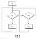
FIG. 5 is a flow chart illustrating exemplary operation of the lighting control unit of FIG. 4.
FIG. 6 is a flow chart illustrating exemplary operation of the lighting system controller of FIG. 3.
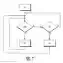
FIG. 7 is a flow chart illustrating exemplary operation of the occupancy detector of FIG. 2.
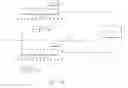
The exemplary embodiment of FIG. 1 illustrates a simple lighting system utilizing the invention. This system includes two local areas A and B, each having a respective light source. The invention is also applicable to a single local area and to lighting systems including many local areas, but the two-area embodiment of FIG. 1 is sufficient to explain the invention in principle.
The local areas A,B include the respective light sources LA, LB for illuminating these areas with sufficient coverage to impinge on any wearable occupancy detectors present. Each of these light sources may include one or more light units (e.g. fluorescent, HID, LED), positioned as necessary to accomplish this purpose. The light emitted by the light units is modulated to identify the specific local area in which it is located. This can be done, for example, by frequency modulating the light in accordance with a code that uniquely identifies the respective local area. The modulation can be continuous or intermittent and is preferably in a frequency range that is not noticeable by the human eye.
The modulation of the light from the light source in one local area should not be detectable by any occupancy detector located in a different local area. In the embodiment of FIG. 1, this is achieved by a wall W, which blocks modulated light MA emitted by light source LA from reaching any occupancy detectors in local area B. Similarly, wall W blocks modulated light MB emitted by light source LB from reaching any occupancy detectors in local area A. Exemplary alternatives to the wall W include directing the modulated light in one local area so that it does not impinge on occupancy detectors in another local area or separating the local areas sufficiently so that modulated light from one local area is too attenuated to be detected when it reaches another local area.
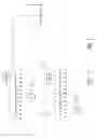
At the instant in time depicted in FIG. 1, wearable occupancy detector D1 is located in local area A and wearable occupancy detectors D2 and D3 are located in local area B. Advantageously, these occupancy detectors are in the form of tags or badges that can be conveniently worn by persons who will occupy the local areas. Preferably, the detectors utilize low-power integrated circuitry to minimize power drain from a power source such as a battery and/or solar-cell array. FIG. 2 illustrates an embodiment of one such occupancy detector D, which includes a light sensor S, a micro-controller unit MCU-D, and an RF transceiver X-D. The light sensor S detects the modulated light in the local area where the detector is situated, extracts the respective local area identifier (e.g. area A), and converts the identifier to a digital signal that is applied to the micro-controller unit MCU-D. This micro-controller unit:
-
- converts the detected local-area identifier to a location code recognizable by a lighting system controller C;
- produces a detector-locator signal representing this location code and, optionally, an ID code identifying the respective occupancy detector in which it is incorporated (e.g. D1); and
- applies this signal to the RF transceiver X-D.
The transceiver X-D transmits an RF signal modulated by the detector-locator signal to effect communication of the encoded information to the lighting system controller C either directly or via a lighting control unit LC.
If coupled directly, the lighting system controller C is located where it can receive the detector-locator signals from the wearable-occupancy detectors D whenever they are in any of the local areas which it is to control. The controller C can be located outside of all local areas, in a local area, and even in one of the light sources itself As shown by the broken lines in FIG. 1, the lighting system controller C and the lighting control units LC are also coupled to each of the light sources. This may be done via any convenient mode, e.g. via wired coupling or wireless couplings such as RF, IR or visible light. FIG. 3 illustrates an exemplary embodiment of a lighting system controller C. In this embodiment, the system controller C includes a transceiver X-C for receiving and transmitting RF communications, a user interface UI for communicating with a person controlling the operation of the lighting system, and a micro-controller unit MCU-C for processing all of these communications.
In one embodiment of the invention, the system controller C receives the detector-locator signals directly from the wearable-occupancy detectors. In another embodiment (described in detail in this application), these signals are relayed to the lighting system controller, e.g. via one or more of the lighting control units LC. Advantageously, these units LC may be incorporated in one or more of the light sources. FIG. 4 illustrates an embodiment of a lighting control unit LC. In this embodiment, the lighting control unit LC includes a transceiver X-LC for receiving and transmitting RF communications, light driver circuitry LDR for the type of light sources being used, and a micro-controller unit MCU-LC. This micro-controller unit converts signals that it provides to and receives from the transceiver X-LC in accordance with protocols used in the lighting system. For example, commands and other information (such as detector and local area identifiers) might be conformed to the DALI standard and embedded in an RF communication protocol such as ZIGBEE. The micro-controller unit MCU-LC also controls the light driver circuitry LDR to:
-
- modulate the illumination light produced by the respective light source to identify the local area in which it is situated;
- perform basic functions, e.g. turning the light source on or off, dimming the light output, etc., in accordance with commands received from the lighting system controller C.
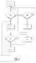
FIG. 5 illustrates exemplary operation of the micro-controller unit MCU-LC in the lighting control unit LC shown in FIG. 4. Specifically:
-
- At NI the lighting control unit LC is initialized via transmissions through its transceiver X-LC. Initialization is a procedure whereby the lighting system controller C assigns respective network ID codes to all components that join the network. Note that there can be more than one lighting control unit for a local area. For example, a light source for a local area may include a number of light units, each having a lighting control unit LC. In this case one of these lighting control units in the respective local area may be advantageously operated as a master and the others as slaves. A detailed description of one way in which initialization in such a master-slave arrangement may be done is given in U.S. patent application Ser. No. 10/323,414 filed on 19 Dec. 2002, which is hereby incorporated by reference.
- At RC the lighting control unit LC determines whether it is receiving any signals or commands indicating that the local area should be lighted for a person. Such a determination can be made in a variety of ways, depending on the way that the lighting system is set up. For example: (i) The detectors D can each continually emit an RF signal detectable by the transceiver X-LC in a lighting control unit when the person with the detector enters the respective area, thereby causing the light source in the area to transmit the modulated light with the respective local-area identifier. (ii) When a person with a detector leaves a first local area (and the detector no longer transmits the locator signal for that area) the lighting system controller C could command one or more lighting control units in adjacent local areas to illuminate those areas. (iii) IR sensors along pathways to or in local areas could sense the entry of a person into a local area and send the respective lighting control unit a signal indicating that a person is entering the area.
- If it is not receiving a signal or command to light the local area, at ROP the micro-controller unit MCU-LC determines whether any other commands (e.g. dimming commands) or signals (e.g., in an automated environment-control system, sensed temperature or ambient light level for the respective local area) are being received from the transceiver.
- If no, the micro-controller unit returns to RC.
- If yes, the micro-controller unit processes the commands or signals at PPI and returns to RC.
- If it is receiving a signal or command to light the local area, at PCT micro-controller unit MCU-LC causes the light driver circuitry LDR to illuminate the respective local area with light that is modulated to identify the local area (e.g. local area B) and goes to RID.
- If it is not receiving a signal or command to light the local area, at ROP the micro-controller unit MCU-LC determines whether any other commands (e.g. dimming commands) or signals (e.g., in an automated environment-control system, sensed temperature or ambient light level for the respective local area) are being received from the transceiver.
- At RID the lighting control unit continuously or intermittently modulates the light in the local area and determines whether a correct response from any occupancy detector(s) D located in the respective local area are received. A correct response will be a detector-locator signal that includes a code for the respective local area. For example, if the lighting control unit is controlling the illumination of local area B, a correct response for a detector in this area will include a code identifying local area B.
- If a correct response is received the lighting control unit will go to RLI and transmit the location code via the transceiver X-LC to the lighting system controller C, indicating that a person is in the respective local area, and return to RC. If the detector-locator signal from the occupancy detector also includes an ID code identifying the individual detector, this information will also be transmitted to the lighting system controller.
- If a correct response is not received, the micro-controller unit MCU-LC in the respective lighting control unit will:
- go to PDT and perform a default task, e.g. cause the light driver circuitry LDR for the respective light source to dim or extinguish the local area lighting;
- go to RLI and inform the lighting system controller C that no occupant is in the respective local area; and
- return to RC.
FIG. 6 illustrates exemplary operation of the micro-controller unit MCU-C in the lighting system controller C shown in FIG. 3. Specifically:
-
- At NI the lighting system controller initializes into a communication network the occupancy detectors D, the lighting control unit LC, and possibly other components that are capable of communicating with the controller. In the exemplary lighting system of FIG. 1, this would include the wearable occupancy detectors D1,D2,D3 and lighting control units LC-A and LC-B (not shown) associated with the light sources LA and LB, respectively. All of these components would be initialized via RF communications passing through respective transceivers of the components.
- At RDL the lighting system controller C determines whether its transceiver X-C is receiving any detector-location codes and detector ID codes from the lighting control units in the system.
- If yes, at UOI micro-controller unit MCU-C updates a look-up table in the unit to indicate that a wearable occupancy detector D has been detected in the identified local area and, if included, the identity of the detector. It then returns to RDL. The look-up table may also include other information relevant to the detector, such as the identity of the person who was issued the detector.
- If no, at ROC the micro-controller unit MCU-C checks whether any commands or requests have been received via the user interface UI or the transceiver X-C.
- If no, the micro-controller unit returns to RDL.
- If yes, the micro-controller unit performs the required action and returns to RDL. Examples of such actions include issuing a command to dim the lighting in a specific local area in response to a command from the user interface and initializing a system component in response to a request.
As another example of an action to be taken at UOI, if the look-up table specifies that local area A should be lighted whenever an occupant is present and the received detector-location code indicates that a wearable occupancy detector is present in local area A, the micro-controller unit MCU-C would issue a command to the lighting control unit for light source LA (transmitted by transceiver X-C) to light local area A. The look-up table could be permanent or it could be readily updated, e.g. via the user interface UI.
As another example, one or more look-up tables could specify the security clearances of different persons who have been issued wearable occupancy detectors and the security clearances required for access to different local areas. An action to be taken by micro-controller unit MCU-C at UOI could then be to verify whether a person issued the detector located in a specific local area has the required clearance for the area. Alternatively, this could be done at ROC and PCT in response to a command from the user interface UI.
Occupancy Detector OperationFIG. 7 illustrates exemplary operation of the wearable occupancy detector D shown in FIG. 2. Specifically:
-
- At NI each occupancy detector D is initialized whenever it enters within RF range of a lighting control unit LC.
- At RML the micro-controller unit MCU-D in the occupancy detector determines whether it is receiving modulated light in a local area.
- If yes, at SLI it transmits the detector-locator signal identifying the local area in which it is located, and optionally a unique detector ID code. This information is relayed to the lighting system controller C by the respective lighting control unit LC. The micro-controller unit MCU-D then returns to RML.
- If no, at RP it determines whether any commands or requests are being received via the transceiver X-D (e.g. a command from the lighting system controller C for all detectors within transmission range of lighting control units LC to identify themselves).
- If no, the micro-controller unit returns to RML.
- If yes, the micro-controller unit processes the command or request at PPI and returns to RML.
While exemplary embodiments of the invention are described, various modifications and changes can be made without departing from the spirit and scope of the invention. It is therefore to be understood that the invention includes all embodiments that fall within the scope of the appended claims.
AlternativesAlthough D/C/LC shown as communicating via RF, could also be wired and/or other type of wireless than RF.
Claims
What is claimed is:1. A lighting control arrangement comprising:
a. a light source (LA) for emitting light to illuminate a local area, said light being modulated to identify the local area;
b. a wearable occupancy detector (D) for radiating a signal in response to detection of the modulated light, said radiated signal identifying the local area;
c. a control unit (LC) in communication with the light source, said control unit being capable of controlling a lighting function of said light source in response to reception of said radiated signal.
2. A lighting control arrangement as in claim 1 where the radiated signal is capable of traveling beyond the local area.
3. A lighting control arrangement as in claim 1 where the control unit directly receives the radiated signal.
4. A lighting control arrangement as in claim 1 where the signal radiated by the wearable occupancy detector identifies said detector.
5. A lighting control arrangement as in claim 1 where the signal radiated by the wearable occupancy detector identifies a particular person.
6. A lighting control arrangement comprising:
a. a first light source (LA) for emitting light to illuminate a first local area, said light being modulated to uniquely identify said first local area;
b. a second light source (LB) for emitting light to illuminate a second local area, said light being modulated to uniquely identify said second local area;
c. a wearable occupancy detector (D) for radiating a signal in response to detection in either of the first and second local areas of the modulated light from the respective light source, said signal identifying the local area in which said detector is located;
d. at least one control unit (LC) in communication with the first and second light sources, said at least one control unit being capable of controlling a lighting function of each of said light sources in response to reception of said radiated signal.
7. A lighting control arrangement as in claim 6 where the at least one control unit comprises first and second control units, each in communication with a respective one of the first and second light sources.
8. A lighting control arrangement as in claim 6 where the radiated signal is capable of traveling beyond at least one of the first and second local areas.
9. A lighting control arrangement as in claim 6 where the at least one control unit directly receives the radiated signal.
10. A lighting control arrangement as in claim 6 where the signal radiated by the wearable occupancy detector identifies said detector.
11. A lighting control arrangement as in claim 6 where the signal radiated by the wearable occupancy detector identifies a particular person.
12. A lighting control system comprising:
a. a plurality of light sources (LA, LB) for emitting light to illuminate respective local areas, said light being modulated to identify the local areas;
b. a wearable occupancy detector (D) for radiating a signal in response to detection of the modulated light, said radiated signal identifying the local area in which it is located;
c. at least one control unit (LC) in communication with the light sources and being capable of controlling a lighting function of said light sources;
d. a lighting system controller (C) in communication with the at least one control unit for controlling operation of the control unit in response to reception of said radiated signal.
13. A lighting control system as in claim 12 where the lighting system controller directly receives said radiated signal.
14. A lighting control system as in claim 12 where the lighting system controller indirectly receives said radiated signal via a communication from the at least one control unit.
15. A lighting control system as in claim 12 where the at least one control unit comprises first and second control units, each in communication with a respective one of the light sources.
16. A lighting control system as in claim 12 where the at least one control unit directly receives the radiated signal.
17. A lighting control system as in claim 12 where the signal radiated by the wearable occupancy detector identifies said detector.
18. A lighting control system as in claim 12 where the signal radiated by the wearable occupancy detector identifies a particular person.
Images & Drawings included:
Sources:
- United States Patent and Trademark Office - verify current appl. status at the USPTO↗
Similar patent applications:
Recent applications in this class:
- » 20250287487 2025-09-11
Control Device - » 20250280480 2025-09-04
INFORMATION PROCESSING APPARATUS, INFORMATION PROCESSING METHOD, AND INFORMATION PROCESSING PROGRAM - » 20250203734 2025-06-19
SYSTEM AND METHOD FOR MODIFYING A LIVING ENVIRONMENT TO ASSIST IN FALL PREVENTION - » 20250159778 2025-05-15
CONFIGURING A LOAD CONTROL SYSTEM - » 20250159777 2025-05-15
INTEGRATED ILLUMINATION MODULE, MONITORING ARRANGEMENT AND METHOD OF OPERATING A MONITORING ARRANGEMENT - » 20250159776 2025-05-15
A CONTROL DEVICE FOR OF POWER SHARING BETWEEN AT LEAST TWO LIGHTING DEVICES AND A METHOD THEREOF - » 20250106968 2025-03-27
NOTIFYING OTHERS OF DETECTION STATUS TO MITIGATE ACCIDENT RISK - » 20250106967 2025-03-27
DEVICE AND METHOD - » 20250098054 2025-03-20
LIGHTING SYSTEM - » 20250089144 2025-03-13
LUMINOUS PANEL WITH POWER SUPPLY MEANS FOR SUPPLYING POWER TO ATTACHED DEVICE
Recent applications for this Assignee:
- » 20210337645 2021-10-28
METHOD AND ADJUSTMENT SYSTEM FOR ADJUSTING SUPPLY POWERS FOR SOURCES OF ARTIFICIAL LIGHT - » 20210290972 2021-09-23
BODY ILLUMINATION SYSTEM USING BLUE LIGHT - » 20190191921 2019-06-27
METHOD AND SYSTEM FOR BREWING INGREDIENTS IN A SOLVENT, APPARATUS USING SAID SYSTEM - » 20170325686 2017-11-16
System and method for extracting physiological information from remotely detected electromagnetic radiation - » 20150380899 2015-12-31
Eye-safe laser-based lighting - » 20150305720 2015-10-29
Ultrasonic synthetic transmit focusing with motion compensation - » 20150189712 2015-07-02
LED lighting arrangement and method of controlling a LED lighting arrangement - » 20150181667 2015-06-25
Driver circuit between fluorescent ballast and LED - » 20150171273 2015-06-18
Solid state light emitting devices based on crystallographically relaxed structures - » 20150146407 2015-05-28
Lighting device having a remote wavelength converting layer