Flat material for leadthroughs
US20070148394A1
2007-06-28
11/640,070
2006-12-14
✅ Patent granted
US 7,615,275 B2
2009-11-10
-
-
Alexander Thomas
2027-07-24
Abstract:
A flat material (10) for forming leadthroughs and including a first layer (11) formed of strip-shaped plates (14) adjoining each other along their narrow sides and separated from each other by a slot (15), a second layer (13) formed of an elastic material, and an intermediate layer (12) located between the first layer (11) and the second layer (13).
Inventors:
- Herbert Muenzenberger 41 🇩🇪 Wiesbaden, Germany
- Christian Foerg 21 🇩🇪 Dillishausen, Germany
- Heiri Nuesch 1 🇨🇭 Sevelen, Switzerland
Assignee:
- Hilti Aktiengesellschaft 1,520 Schaan, Liechtenstein
Interested in similar patents?
Get notified when new applications in this technology area are published.
Classification:
B32B3/16 IPC
Layered products comprising a layer with external or internal discontinuities or unevennesses, or a layer of non-planar form ; Layered products having particular features of form characterised by a discontinuous layer, i.e. formed of separate pieces of material characterised by a face layer formed of separate pieces of material which are juxtaposed side-by-side secured to a flexible backing
E04G15/061 » CPC main
Forms or shutterings for making openings, cavities, slits, or channels for cavities or channels in walls of floors, e.g. for making chimneys Non-reusable forms
F16L5/02 » CPC further
Devices for use where pipes, cables or protective tubing pass through walls or partitions Sealing
F16L5/04 » CPC further
Devices for use where pipes, cables or protective tubing pass through walls or partitions; Sealing to form a firebreak device
H02G3/0462 » CPC further
Installations of electric cables or lines in or on buildings, equivalent structures or vehicles; Details; Protective tubings or conduits or channels or other supports Tubings, i.e. having a closed section
Y10S428/92 » CPC further
Stock material or miscellaneous articles Fire or heat protection feature
Y10S428/921 » CPC further
Stock material or miscellaneous articles; Fire or heat protection feature Fire or flameproofing
Y10T428/183 » CPC further
Stock material or miscellaneous articles; Longitudinally sectional layer of three or more sections Next to unitary sheet of equal or greater extent
Y10T428/187 » CPC further
Stock material or miscellaneous articles; Longitudinally sectional layer of three or more sections; Next to unitary sheet of equal or greater extent Continuous sectional layer
Y10T428/2476 » CPC further
Stock material or miscellaneous articles; Structurally defined web or sheet [e.g., overall dimension, etc.]; Laterally noncoextensive components Fabric, cloth or textile component
Y10T442/133 » CPC further
Fabric [woven, knitted, or nonwoven textile or cloth, etc.]; Scrim [e.g., open net or mesh, gauze, loose or open weave or knit, etc.]; Woven scrim Inorganic fiber-containing scrim
Y10T442/172 » CPC further
Fabric [woven, knitted, or nonwoven textile or cloth, etc.]; Scrim [e.g., open net or mesh, gauze, loose or open weave or knit, etc.]; Woven scrim Coated or impregnated
Y10T442/176 » CPC further
Fabric [woven, knitted, or nonwoven textile or cloth, etc.]; Scrim [e.g., open net or mesh, gauze, loose or open weave or knit, etc.]; Woven scrim; Coated or impregnated Three or more layers
Y10T442/198 » CPC further
Fabric [woven, knitted, or nonwoven textile or cloth, etc.]; Scrim [e.g., open net or mesh, gauze, loose or open weave or knit, etc.]; Nonwoven scrim Coated or impregnated
B32B5/04 IPC
Layered products characterised by the non- homogeneity or physical structure, i.e. comprising a fibrous, filamentary, particulate or foam layer; Layered products characterised by having a layer differing constitutionally or physically in different parts characterised by structural features of a layer characterised by a layer being specifically extensible by reason of its structure or arrangement, e.g. by reason of the chemical nature of the fibres or filaments
Description
BACKGROUND OF THE INVENTION
1. Field of the Invention
The present invention relates to a flat material for leadthroughs.
2. Description of the Prior Art
A leadthrough flat material is used for lining up of inner walls of openings formed in constructional components such as, e.g., walls or ceilings through which pipes, cables, cable channels and the like are extendable.
With such leadthroughs, an opening, which is formed in a constructional component, is lined up with a protective or clad tube. Through this protective or clad tube, a conduit is inserted and is sealed relative to the protective tube.
German Publication DE 103 13 305 A discloses a clad tube for forming leadthroughs which is formed of a substantially cylindrical basic tube surrounded with a plurality of circumferentially arranged lamellas and having at its opposite end regions, sections, respectively, having a larger diameter.
A drawback of such protective or clad tubes consists in that they can be used only for forming leadthroughs having a certain diameter, i.e., the diameter of the clad tube should correspond to the size of the opening.
Accordingly, an object of the present invention is to provide a material for leadthroughs with which the above-mentioned drawback is eliminated and which is flexible in use, i.e., is capable to accommodate opening with different sizes.
SUMMARY OF THE INVENTION
This and other objects of the present invention, which will become apparent hereinafter, are achieved by providing a flat material having a first layer formed of strip-shaped plates adjoining each other along their narrow sides and separated from each other by a slot, a second layer formed of an elastic material, and an intermediate layer located between the first and second layers.
With slots provided between the rigid strip-shaped plates, protective tube for leadthroughs having different sizes, can be easily formed by folding or bending the flat material. Upon bending the flat material to form a tube, the slots between adjacent plates become closed. Further, the flat material can be easily cut at the slots between the adjacent strip-shaped plates, whereby pieces of different length can be produced. Still further, the inventive flat material permits to form protective tubes for leadthroughs, which can be easily separated in a plurality of sections because the inventive flat material is easily foldable along the slots. Thus, separation of conduit junctions in the leadthrough becomes possible.
The strip-shaped plates have, advantageously, a width from 10 to 50 mm, preferably, from 15 to 25 mm.
Advantageously, the intermediate layer is formed of a little stretchable material having the maximum yield limit of about 10%. Thereby, the intermediate layer prevents, in particular, the second layer, which is formed of an elastic material, from overstretching or even splitting during mounting. However, the little stretchable material should be easily bendable to insure a good rolling-up of the flat material.
The little stretchable material is advantageously formed as a fabric. Preferably, the little stretchable material is formed as a glass fiber fabric that has a high tensile strength and, simultaneously, a satisfactory bending characteristics. Alternatively, the little stretchable material can be formed as metal cloth.
Advantageously, the elastic material of the second layer is formed as an elastic coating which is applied, during the manufacturing of the flat material on the first layer with the intermediate layer lying thereon. Alternatively, the elastic material can be formed preliminary as a band to be, e.g., glued to the first layer with the intermediate layer.
It is further advantageous when the elastic material of the second layer is formed as an intermescent coating material. Thereby, a conduit that passes through a protective tube formed of the inventive flat material, can be sealed directly by the protective tube in case of fire.
A high thermal and mechanical bearing capacity of the inventive flat material is achieved by forming the strip-shaped plates of sheet steel.
Advantageously, the inventive flat material is formed as a continuous material that can be cut to length. This insures a cost-effective manufacturing of the inventive flat material and its flexible use. The inventive flat material can, thus, be made available in form of wound-up rolls.
The novel features of the present invention, which are considered as characteristic for the invention, are set forth in the appended claims. The invention itself, however, both as to its construction and its mode of operation, together with additional advantages and objects thereof, will be best understood from the following detailed description of the preferred embodiment, when read with reference to the accompanying drawings.
BRIEF DESCRIPTION OF THE DRAWINGS
The drawings show:
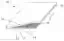
FIG. 1 a perspective partially cross-sectional view of a flat material according to the present invention for leadthroughs; and
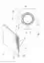
FIG. 2 an elevational view showing a leadthrough located in a constructional component with a pipe arranged in the leadthrough.
DETAILED DESCRIPTION OF THE PREFERRED EMBODIMENT
A flat material 10 according to the present invention for forming leadthroughs for conduits and the like, which is shown in FIG. 1, is formed as a rolled-up continuous material. The flat material 10 is formed of three layers. The first layer 11 is formed of metal strip-shaped plates 14 such as, e.g., steel metal plates or aluminum metal plates that extend parallel to each other and transverse to a longitudinal direction L of the flat material 10. The strip-shaped plates have a width of 25 mm. The second layer 13 is formed of an elastic intermescent material formed as a coating provided on the first layer 11. The elastic intumescent material consists, e.g., of a matrix of latex, acrylate, polyurethane, or another elastic plastic material and into which intermescent components such as, e.g., swelling graphite, are brought in.
Between the first layer 11 and the second layer 13, there is further provided an intermediate layer 12 formed of a little stretchable material with a yield limit of about 5%, such as, e.g., a wide-meshed glass fiber fabric. Instead of the glass fiber fabric, e.g., a plastic or natural fiber fabric, plastic foil, or a multiplicity of threads, cords, or straps of a plastic glass, or natural fiber which extend parallel to each other in the longitudinal direction L of the flat material, can be used. The little stretchable material can also consist of a knitted plastic, natural, or glass fiber material. Under natural fibers, fibers or yams of cotton, wool, linen, or plant fibers such as, e.g., jute or sisal, are understood.
Because of slots 15 provided between the strip-shaped plates 14 of the first layer 11, the flat material 10 is easily rolled up in its longitudinal direction L and, thus, can be made available in form of rolls (not shown in the drawings). Further, the slots 15 insure that the flat material 10 can be easily bent, folded, or separated thereat.
FIG. 2 shows a leadthrough 40 formed by cutting the inventive flat material 10 to a length corresponding to an inner circumference of an opening 21 and forming a clad tube therefrom. The flat material 10 lines up the opening 10 in a constructional component 20, e.g., a wall. A sealing mass 41 fills the space between the inner wall of the opening 21 and the first layer 11 of the flat material 10 to fill remaining intermediate cavities and gaps. The sealing mass 41 can be formed, e.g., as an intumescent mass. A conduit 30, which is formed, e.g., as a pipe conduit, passes through the leadthrough 40 and sealingly abuts the second layer 13 that is formed of an elastic material.
If, as a result of the shape of the pipe conduit 30, the second layer 13 does not tightly abut the pipe conduit 30, the sealing mass 41 is used for filling any gaps. Besides any intumescent sealing mass, plaster or mortar can also be used.
Though the present invention was shown and described with references to the preferred embodiment, such is merely illustrative of the present invention and is not to be construed as a limitation thereof and various modifications of the present invention will be apparent to those skilled in the art. It is therefore not intended that the present invention be limited to the disclosed embodiment or details thereof, and the present invention includes all variations and/or alternative embodiments within the spirit and scope of the present invention as defined by the appended claims.
Claims
What is claimed is:1. A flat material (10) for leadthroughs, comprising:
a first layer (11) formed of strip-shaped plates (14) adjoining each other along narrow sides thereof and separated from each other by a slot (15);
a second layer (13) formed of an elastic material; and
an intermediate layer (12) located between the first layer (11) and the second layer (13).
2. A flat material according to claim 1, wherein the intermediate layer (12) is formed of a little stretchable material.
3. A flat material according to claim 2, wherein the little stretchable material is a fabric.
4. A flat material according to claim 2, wherein the little stretchable material is a glass fiber fabric.
5. A flat material according to claim 1, wherein the elastic material of the second layer (13) is an elastic coating.
6. A flat material according to claim 1, wherein the elastic material of the second layer (13) is an intumescent coating material.
7. A flat material according to claim 1, wherein the strip-shaped plates (14) are formed of metal.
8. A flat material according to claim 7, wherein the strip-shaped plates (14) are formed of sheet steel.
9. A flat material according to claim 1, wherein the flat material is formed as a continuous material cuttable to length.
Images & Drawings included:
Sources:
- United States Patent and Trademark Office - verify current appl. status at the USPTO↗
Recent applications in this class:
- » 20250122737 2025-04-17
Cast-In-Place Device for Creating a Partition Passageway with Firestop and Water-Tight Seal - » 20240410187 2024-12-12
VENT FOR A VENTILATED CONCRETE FLOOR STRUCTURE AND METHOD OF FORMING A VENTILATED CONCRETE FLOOR STRUCTURE - » 20240151048 2024-05-09
CEMENT FORM WITH BRICK LEDGE - » 20210230889 2021-07-29
Blockout assembly for supporting conduits through concrete panels - » 20210180343 2021-06-17
Systems and methods for an indicator system in firestop protection systems - » 20210102391 2021-04-08
Isolation pocket form and method for making crack resistant concrete slabs - » 20210087837 2021-03-25
Method of constructing hollow wall structure - » 20200299980 2020-09-24
Rough-in Box for Creating Penetrations in Poured Concrete Flooring and Method of Use - » 20200217092 2020-07-09
Method for firestop through-penetrations - » 20190390471 2019-12-26
Rough-in box for creating penetrations in poured concrete flooring and method of use
Recent applications for this Assignee:
- » 20250243117 2025-07-31
Two-component mortar system based on aluminous cement and use thereof - » 20250187982 2025-06-12
USE OF CALCIUM SULFATE IN AN INORGANIC MORTAR SYSTEM BASED ON ALUMINOUS CEMENT AND GROUND-GRANULATED BLAST-FURNACE SLAG TO INCREASE LOAD VALUES - » 20250179346 2025-06-05
TWO-COMPONENT MORTAR SYSTEM BASED ON ALUMINOUS CEMENT AND GROUNDGRANULATED BLAST-FURNACE SLAG AS WELL AS USE THEREOF - » 20250178974 2025-06-05
TWO-COMPONENT MORTAR SYSTEM BASED ON ALUMINOUS CEMENT AND CALCIUM SILICATE AS WELL AS USE THEREOF - » 20250178963 2025-06-05
STABILIZED AQUEOUS COMPOSITION BASED ON BLOCKED CALCIUM SILICATE CEMENT FOR INITIATING SETTING AND HARDENING OF ALUMINOUS CEMENT COMPOSITIONS - » 20250178960 2025-06-05
STABILIZED AQUEOUS COMPOSITION BASED ON BLOCKED GROUND-GRANULATED BLAST-FURNACE SLAG FOR INITIATING SETTING AND HARDENING OF ALUMINOUS CEMENT COMPOSITIONS - » 20250164040 2025-05-22
CAST-IN-PLACE THROUGH-PENETRATION FIRESTOP DEVICE - » 20250115704 2025-04-10
FOAMABLE MULTI-COMPONENT COMPOSITION, AND FOAMED FIRE-PROTECTION PROFILE HAVING TEMPERATURE-REGULATING FILLERS - » 20250090879 2025-03-20
COMPOSITE MATERIAL AND FIRE PROTECTION ELEMENT FOR SEALING PASSAGE OPENINGS AND JOINTS IN COMPONENTS - » 20250088012 2025-03-13
Power tool and method for carrying out charge equalization between accumulators in a power tool