Supporting frame for CCTV camera enclosure
US20070165137A1
2007-07-19
11/332,333
2006-01-17
✅ Patent granted
US 7,599,000 B2
2009-10-06
-
-
Jason Chan | Leslie Virany
2027-11-01
Abstract:
A support frame for CCTV camera enclosure is disclosed. The support frame comprises a support body supporting the structure of the support frame; a rotating section mounted onto the support body and the rotating section horizontally rotated with respect to the axial hole via the support body; a securing section mounted onto the rotating section and the securing section being rotated vertically; and a contact face with protruded teeth corresponding to the rotating section and the securing section to secure the CCTV camera in a best position.
Interested in similar patents?
Get notified when new applications in this technology area are published.
Classification:
H04N5/225 IPC
Details of television systems; Studio circuitry; Studio devices; Studio equipment ; Cameras comprising an electronic image sensor, e.g. digital cameras, video cameras, TV cameras, video cameras, camcorders, webcams, camera modules for embedding in other devices, e.g. mobile phones, computers or vehicles Television cameras ; Cameras comprising an electronic image sensor, e.g. digital cameras, video cameras, camcorders, webcams, camera modules specially adapted for being embedded in other devices, e.g. mobile phones, computers or vehicles
G05B17/00 IPC
Systems involving the use of models or simulators of said systems
F16M13/02 » CPC main
Other supports for positioning apparatus or articles ; Means for steadying hand-held apparatus or articles for supporting on, or attaching to, an object, e.g. tree, gate, window-frame, cycle
F16M11/08 » CPC further
Stands or trestles as supports for apparatus or articles placed thereon Stands for scientific apparatus such as gravitational force meters; Heads; Means for attachment of apparatus; Means allowing adjustment of the apparatus relatively to the stand allowing pivoting around a vertical axis, e.g. panoramic heads
F16M11/2021 » CPC further
Stands or trestles as supports for apparatus or articles placed thereon Stands for scientific apparatus such as gravitational force meters; Undercarriages with or without wheels comprising means allowing pivoting adjustment around a horizontal axis
G08B13/19632 » CPC further
Burglar, theft or intruder alarms; Actuation by interference with heat, light, or radiation of shorter wavelength; Actuation by intruding sources of heat, light, or radiation of shorter wavelength using passive radiation detection systems using image scanning and comparing systems using television cameras; Surveillance camera constructional details Camera support structures, e.g. attachment means, poles
F16M2200/022 » CPC further
Details of stands or supports; Locking means for rotational movement by friction
Description
BACKGROUND OF THE INVENTION(a) Technical Field of the Invention
The present invention relates to supporting frame, and in particular, to a support frame which supports or holds a CCTV camera enclosure.
(b) Description of the Prior Art
On many roads or lanes in a city or town, or in public plates such as bus stations, taxi stations or train stations, CCTV cameras are now widely installed so as to monitor or to record the status of these places to minimize the crimes carried out in these places. Generally, the CCTV camera is fixed such that the CCTV is allowed to move up and down and the horizontal angle adjustment. Therefore, it is important that the support frame for the CCTV enclosure is important. Taiwan Patent No. 2676939 is related to the base for a CCTV having a body, a securing section and a connection to the securing section. There are two ways of horizontal rotations in order to see all position. The drawback of this CCTV is the exposure of wire outside a shade and therefore, the wires may be damaged after sometime of use.
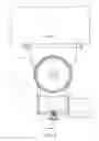
As shown in FIG. 1, in order to solve the above drawback, the support frame is designed in such a way that the interior is hollow, and the wiring is positioned within the frame to connect with the enclosure. Therefore, the wirings are kept from exposure. However, the contact face 100 is connected by means of bolt 200 and nut 300 which facilitates mounting but the contact surface is small and therefore, the enclosure may be dislocated due to external force, or the angle of enclosure is altered to dislocate.
Accordingly, it is an object of the present invention to provide a supporting frame for CCTV camera enclosure which mitigate the above drawback.
SUMMARY OF THE INVENTIONThe primary purpose of the present invention is to provide a support frame for CCTV enclosure comprising a support body supporting the structure of the support frame; a rotating section mounted onto the support body and the rotating section horizontally rotated with respect to the axial hole via the support body; a securing section mounted onto the rotating section and the securing section being rotated vertically; and a contact face with protruded teeth corresponding to the rotating section and the securing section to secure the CCTV camera in a best position.
Yet another object of the present invention is to provide a supporting frame for CCTV camera enclosure, wherein the interior of the support frame is hollow to allow wiring of the CCTV camera to pass through to the CCTV camera enclosure.
The foregoing object and summary provide only a brief introduction to the present invention. To fully appreciate these and other objects of the present invention as well as the invention itself, all of which will become apparent to those skilled in the art, the following detailed description of the invention and the claims should be read in conjunction with the accompanying drawings. Throughout the specification and drawings identical reference numerals refer to identical or similar parts.
Many other advantages and features of the present invention will become manifest to those versed in the art upon making reference to the detailed description and the accompanying sheets of drawings in which a preferred structural embodiment incorporating the principles of the present invention is shown by way of illustrative example.
BRIEF DESCRIPTION OF THE DRAWINGSFIG. 1 is a perspective exploded view of a conventional support frame for CCTV camera.
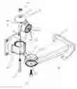
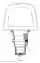
FIG. 2 is a perspective exploded view of the support frame for CCTV camera in accordance with the present invention.
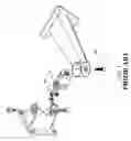
FIG. 3 is a perspective view of the support frame for CCTV camera of the present invention.
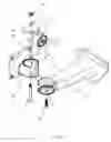
FIG. 4 is a schematic view of the support frame for CCTV camera of the present invention.
FIG. 5 is a sectional view of the support frame for CCTV camera of the present invention.
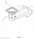
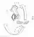
FIG. 6 is a schematic view showing the implementation of the support frame for CCTV camera of the present invention.
DETAILED DESCRIPTION OF THE PREFERRED EMBODIMENTSThe following descriptions are of exemplary embodiments only, and are not intended to limit the scope, applicability or configuration of the invention in any way. Rather, the following description provides a convenient illustration for implementing exemplary embodiments of the invention. Various changes to the described embodiments may be made in the function and arrangement of the elements described without departing from the scope of the invention as set forth in the appended claims.
Referring to FIGS. 2 and 3, there is shown a support frame for a CCTV camera enclosure comprising a support body 10, a rotating section 20 and a securing section 30. In accordance with the present invention, the interior of the frame body 10, the rotating section 20 and the securing section 30 is hollow, and their respective corresponding faces are contact face 40 with protruded teeth facilitating locking by bolt and nut.
As shown in FIGS. 4 and 5, the contact face 40 at the lower section of the rotating section is mounted within the front end recess 11 of the support body, and the contact face is provided with circular protrusions 21 which is mountable with the circular slot 12 of the recess 11. There is a threaded hole 22 on the center of the circular protrusions and the surroundings of the circular protrusions are symmetrical, protruded block 23. There is a through hole 13 and a limiting block 14 within the circular slot, and the teeth of the contact face allow the engagement of the through hole 13 and the limiting block 14, and a bolt via the through hole within the recess the support body 12 is locked at the threaded hole.
The top of the rotating section 20 is connected to a circular disc 24 and the contact face 40 on the circular disc 24 is in engagement with the securing section 30. The circular disc is provided with a hexagonal recess 24 and a through hole, and at a position corresponding to the securing section, a holding hole 31 is provided. The rotating section and the securing section are linked to each other by the nut 52 within the hexagonal slot and the bolt 351. The top end of the securing section is a securing plate 32 for securing the camera enclosure.
When the CCTV camera enclosure is to be mounted on a wall, the bolt first secures the securing seat 15 of the support body 10, and the enclosure is positioned at the securing plate 32 of the securing section 30, and the connection wiring of the enclosure passes through the interior of the support body, the rotating section and the securing section 30 to the enclosure. By releasing the bolt on the support frame, the rotating section causes a horizontal rotation of the transverse shaft of the support body and the securing section cause the rotating section to rotate vertically. The range of rotating section is restricted by the limiting block 14 and the protruded block 23. The two types of axial rotation (as shown in FIG. 6), the CCTV camera on the support frame can be adjusted in all angles.
It will be understood that each of the elements described above, or two or more together may also find a useful application in other types of methods differing from the type described above.
While certain novel features of this invention have been shown and described and are pointed out in the annexed claim, it is not intended to be limited to the details above, since it will be understood that various omissions, modifications, substitutions and changes in the forms and details of the device illustrated and in its operation can be made by those skilled in the art without departing in any way from the spirit of the present invention.
Claims
I claim:1. A support frame for CCTV enclosure comprising
a support body supporting the structure of the support frame;
a rotating section mounted onto the support body and the rotating section horizontally rotated with respect to the axial hole via the support body;
a securing section mounted onto the rotating section and the securing section being rotated vertically; and
a contact face with protruded teeth corresponding to the rotating section and the securing section to secure the CCTV camera in a best position.
2. The support frame for CCTV enclosure of claim 1, wherein the interior of the support frame is hollow to allow wiring of the CCTV camera to pass through to the CCTV camera enclosure.
Images & Drawings included:
Sources:
- United States Patent and Trademark Office - verify current appl. status at the USPTO↗
Recent applications in this class:
- » 20250290597 2025-09-18
WALL MOUNTED EQUIPMENT SUPPORT - » 20250290596 2025-09-18
FLOATING MOVING OBJECT AND PROBE MECHANISM - » 20250277558 2025-09-04
BRACKET, SYSTEM AND METHOD FOR HANGING ARTICLES UNDER A STRUCTURE - » 20250271099 2025-08-28
POULTRY FEEDER AND WATERER WITH HANDLE AND SUPPORT PROVIDING AN ADJUSTABLE HEIGHT - » 20250271098 2025-08-28
GRAB BAR ASSEMBLY - » 20250264188 2025-08-21
SEISMIC BRACING YIELD FUSE - » 20250264187 2025-08-21
STAND FOR DISPLAY APPARATUS AND DISPLAY APPARATUS INCLUDING SAME - » 20250243972 2025-07-31
SELF-INSERTING TREE HANGER - » 20250243971 2025-07-31
Mounting system for a tablet - » 20250243970 2025-07-31
RAIL SUPPORTING APPARATUS FOR SUPPORTING TUBULAR RAIL MEMBER FOR BOARDING SPORTS ON A BASE FRAME