Pseudo-isothermal catalytic reactor
US20070166210A1
2007-07-19
10/571,221
2004-08-30
✅ Patent granted
US 7,754,163 B2
2010-07-13
WO; PCT/EP2004/009632; 20040830
WO; WO2005/023411; 20050317
Jennifer A Leung
2025-11-18
Abstract:
Pseudo-isothermal chemical reactor (1) for catalytic reactions with a vertical axis, comprising a substantially cylindrical shell (2), Closed at the opposite ends by upper (4) and lower (3) bottoms respectively, a reaction zone (8) in which a catalytic bed (11) and a plurality of flat, boxed, plate-shaped heat exchangers (12), having the shape of a parallelepiped and having long sides parallel to said vertical axis and short sides perpendicular to it, situated in said reaction zone and supported in an arrangement on parallel cords at a predetermined distance.
Inventors:
- Mirco Tarozzo 50 🇨🇭 Ligornetto, Switzerland
- Ermanno Filippi 117 🇨🇭 Castagnola, Switzerland
- Enrico Rizzi 37 🇮🇹 Casnate con Bernate (CO), Italy
- Enrico RIZZI 53 🇮🇹 Casnate con Bernate, Italy
Assignee:
- Methanol Casale SA 34 🇨🇭 Lugano-Besso, Switzerland
- Methanol Casale S.A. 28 🇨🇭 , Switzerland
Interested in similar patents?
Get notified when new applications in this technology area are published.
Classification:
F28D9/0006 » CPC main
Heat-exchange apparatus having stationary plate-like or laminated conduit assemblies for both heat-exchange media, the media being in contact with different sides of a conduit wall the plate-like or laminated conduits being enclosed within a pressure vessel
B01J8/025 » CPC further
Chemical or physical processes in general, conducted in the presence of fluids and solid particles; Apparatus for such processes with stationary particles, e.g. in fixed beds the fluid flow within the bed being predominantly vertical in a cylindrical shaped bed
B01J8/0285 » CPC further
Chemical or physical processes in general, conducted in the presence of fluids and solid particles; Apparatus for such processes with stationary particles, e.g. in fixed beds Heating or cooling the reactor
B01J2208/0015 » CPC further
Processes carried out in the presence of solid particles; Reactors therefor; Controlling the process; Controlling the temperature by indirect heat exchange with heat exchange elements inside the bed of solid particles Plates; Cylinders
F28D1/03 IPC
Heat-exchange apparatus having stationary conduit assemblies for one heat-exchange medium only, the media being in contact with different sides of the conduit wall, in which the other heat-exchange medium is a large body of fluid, e.g. domestic or motor car radiators with heat-exchange conduits immersed in the body of fluid with plate-like or laminated conduits
F28F3/12 IPC
Plate-like or laminated elements; Assemblies of plate-like or laminated elements Elements constructed in the shape of a hollow panel, e.g. with channels
B01J8/02 IPC
Chemical or physical processes in general, conducted in the presence of fluids and solid particles; Apparatus for such processes with stationary particles, e.g. in fixed beds
Description
FIELD OF APPLICATIONThe present invention, in its most general aspect, refers to a pseudo-isothermal chemical reactor for catalytic reactions, comprising a substantially cylindrical shell closed at the opposite ends by respective bottoms, a reaction zone defined in said shell and in which at least one catalytic bed and a plurality of plate heat exchangers situated in said reaction zone are supported.
In the rest of the description and in the subsequent claims, with the term “pseudo-isothermal reactor” we mean to identify a reactor for chemical reactions in which the reaction temperature is controlled within a limited range of values around a predetermined optimal value.
In particular, the present invention concerns a reactor of the aforementioned type structured so that, with reference to the main axis of the reactor, the crossing of the reaction zone by the reactants and the reaction products takes place in the axial direction.
PRIOR ARTAs is known, the control of the temperature at which a chemical reaction takes place is of great importance, since the performance and process yields of said reaction depend upon it.
Such control takes place by supplying or removing heat, in an appropriate way, to or from the environment in which said reaction is realized.
For such a purpose, heat exchangers crossed by an operating fluid responsible for the transportation of hear are widely used.
In the case of chemical reactors of the considered type (axial pseudo-isothermal reactors) heat exchange units consisting of a plurality of heat plate-shaped, boxed exchangers, embedded in a mass of catalyst are used.
Such heat exchangers are arranged on planes all parallel to each other and parallel to the main axis of the reactor, in order to control and make as uniform as possible to heat exchange between mass of catalyst and operating fluid.
An example of such chemical reactors is presented in document U.S. Pat. No. 4,820,495.
Although advantageous from various points of view, such heat exchange units have a serious and recognized drawback. Indeed, when one wishes to use the entire mass of catalyst as uniformly as possible in the heat exchange, as is generally required, such heat exchange units necessarily comprise different sized plated heat exchangers; for this reason, the production, the storage and the transportation of such exchangers is very laborious and not cost-effective, just as the assembly and operation of the heat exchange units of which they consist is also laborious and not cost-effective.
SUMMARY OF THE INVENTIONThe technical problem underlying the present invention is that of devising a chemical reactor of the aforementioned type having structural and functional characteristics such as to allow effective control of the pseudo-isothermicity of the reaction realized in it, allowing at the same time the use of plated heat exchangers, all of the same size.
The aforementioned technical problem is solved by an axial pseudo-isothermal chemical reactor, comprising a substantially cylindrical shell, with vertical axis, closed at the opposite ends by upper and-lower bottoms respectively, a reaction zone, defined in said shell and in which a catalytic bed and a plurality of flat, boxed, plate-shaped heat exchangers, having the shape of a parallelepiped and having vertical long sides and short sides parallel to a same diameter of the shell, are supported, characterized in that said exchangers are all identical and in that their short sides have the ends arranged on imaginary cylindrical surfaces having the same radius as the inner radius of the shell and centers all arranged on a same diameter of the shell.
Surprisingly, it has been found that, by arranging heat exchangers inside a reactor in the aforementioned way, it is possible to use exchangers all generally of the same size, thus solving the technical problem and overcoming the drawbacks of the prior art as described above.
Further characteristics and advantages of the invention will become clearer from the detailed description of an embodiment of a chemical reactor according to the invention, given hereafter with reference to the attached drawings, for indicative and non-limiting purposes.
BRIEF DESCRIPTION OF THE FIGURESFIG. 1 schematically shows a vertical section view of a chemical reactor for realizing the invention.
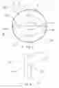
FIG. 2 schematically shows a horizontal section view of the chemical reactor of FIG. 1 without heat exchangers.
FIG. 3 schematically shows a vertical section view of a detail of FIG. 1.
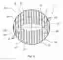
FIG. 4 schematically shows a horizontal section view of the chemical reactor of FIG. 1.
DETAILED DESCRIPTION OF A PREFERRED EMBODIMENT OF THE INVENTIONWith reference to FIGS. 1-4, an axial pseudo-isothermal chemical reactor, with a vertical axis A-A, comprising a substantially cylindrical shell 2, closed at the opposite ends by lower 3 and upper 4 bottoms respectively, is globally and schematically indicated with 1.
The lower bottom 3 is equipped with a mouth 5 for the discharge of the reaction products, whereas the upper bottom 4 is equipped with an opening 6 for the input of the reactants.
Inside said shell 2 a reaction zone 8 is defined, representatively situated between an upper line 9 and a lower line 10, to hold a predetermined catalytic bed 11 (supported in a per se known way and therefore not represented).
Inside said reaction zone 8, and in particular in said catalytic bed 11, a plurality of flat, boxed, plate-shaped heat exchangers 12 having the shape of a parallelepiped is positioned.
Such exchangers 12 have long sides 20, 20a (FIG. 3) parallel to the axis A-A and short sides 21 parallel to the same diameter B of the shell 2.
In particular, to better illustrate the arrangement of such exchangers inside the reaction zone 8, a first exchanger 12 positioned close to the shell 2 is indicated with 12a.
The exchanger 12a has the short side of a predetermined length, extending symmetrically with respect to a diameter C perpendicular to the quoted diameter B.
The opposite ends of said short side, which substantially coincide with the ends, for example the upper ends, of the long sides of the same first exchanger, are arranged on circumferences Z, Z1 respectively, which have the same radius as the inner radius of the shell 2 and the center on the said diameter B.
Consequently, the long sides 20, 20a of said first exchanger 12a, are arranged (FIG. 2 and FIG. 4) on imaginary cylindrical surfaces 22 and 24 with its axis parallel to the main axis of the reactor and, in the aforementioned FIGS. 2 and 4, being in horizontal section, coincide with the circumferences Z, Z1.
The long sides 20, 20a could be compared to generatrices of such imaginary cylindrical surfaces 22 and 24.
The vertical sides 20 and 20a of a first series of exchangers 12 identical to the exchanger 12a, all having parallel short sides of the same predetermined length, belong to the same imaginary cylindrical surfaces 22 and 24, respectively (FIG. 4).
A second series of heat exchangers 12, all having parallel short sides of the same predetermined length is arranged with vertical sides 20 and 20a belonging respectively to the imaginary cylindrical surface 24 and to the imaginary cylindrical surface 26.
Such a cylindrical surface 26 has its axis parallel to the axis A-A of the reactor (and therefore parallel to the axis of the cylindrical surfaces 22 and 24) and passing through the diameter B of the shell 2; moreover, along the same diameter B, the distance between the cylindrical surfaces 24 and 26 and the distance between the cylindrical surfaces 22 and 24 is the same.
Advantageously, the length of said short sides of the exchangers 12 is sized in such a way as to allow easy passage of the exchangers 12 themselves through a manhole opening provided in the upper bottom 4. Such a manhole opening could be the same opening 6 or else an additional opening in the upper bottom 4, not represented.
The opposite ends of the short side of the aforementioned exchanger 12a are also arranged on circumferences Z2, Z3respectively, symmetrical to the circumferences Z, Z1 with respect to the aforementioned diameter C.
Consequently, the long sides 20, 20a of said first exchanger 12a, are arranged (FIG. 2 and FIG. 4), as well as on imaginary cylindrical surfaces 22 and 24, also on imaginary cylindrical surfaces 23 and 25 (which, in the aforementioned FIGS. 2 and 4, coincide with the circumferences Z2, Z3), symmetrical to the cylindrical surfaces 22 and 24 with respect to a plane through the diameter C and the vertical axis A-A.
The vertical sides 20 and 20a of a third series of exchangers 12, all having parallel short sides of the same predetermined length, belong respectively to the same imaginary cylindrical surfaces 23 and 25 (FIG. 4).
A fourth series of heat exchangers 12, all having parallel short sides of the same predetermined length is arranged with the vertical sides 20 and 20a belonging respectively to the imaginary cylindrical surface 25 and of an imaginary cylindrical surface 27.
Such cylindrical surface 27 has its axis parallel to the axis A-A of the reactor (and therefore parallel to the axis of the cylindrical surfaces 23 and 25) and passing through the diameter B of the shell 2; moreover, along the same diameter B, the distance between the cylindrical surfaces 25 and 27 and the distance between the cylindrical surfaces 23 and 25 is the same.
According to a preferred embodiment, said exchangers 12 are arranged on equally spaced parallel imaginary planes.
Moreover, according to a further preferred embodiment, on each of said parallel planes a plurality of heat exchangers 12 is generally arranged, still respecting the constraint of the arrangement of the long sides 20, 20a on the imaginary cylindrical surfaces 22 and 23.
Said exchangers 12 are equipped, above and below, with fittings, 13 and 14 respectively, which allow fluid communication, above with distribution ducts 15 and below with collector ducts 16.
The distribution ducts 15 are in turn in fluid communication with at least one supply duct 17, whereas the collector ducts 16 are in fluid communication with at least one discharge duct 18.
Moreover, an axial manhole passage 19 is centrally defined to ease the assembly and maintenance operations of the reactor.
A chemical reactor of the aforementioned type advantageously allows to control effectively the pseudo-isothermicity of the reaction in every point of the reactor, allowing at the same time the use of plated exchangers generally of the same size.
The invention thus conceived is susceptible to further variants and modifications all of which are within the capabilities of the man skilled in the art and, as such, fall within the scope of protection of the invention itself, as defined by the following claims.
Claims
1. Axial pseudo-isothermal chemical reactor (1), comprising a substantially cylindrical shell (2), with vertical axis (A-A), closed at the opposite ends by upper (4) and lower (3) bottom respectively, a reaction zone (8), defined in said shell (2) and in which a catalytic bed (11) and a plurality of flat, boxed, plate-shaped heat exchangers (12), having the shape of a parallelepiped and having vertical long sides (20) and short sides (21) parallel to a same diameter of the shell (2), are supported, characterized in that said exchangers (12) are all identical and in that their short sides (21) have the ends arranged on imaginary cylindrical surfaces (22, 23, 24, 25, 26, 27) having the same radius as the inner radius of the shell (2) and centers all arranged on a same diameter of the shell (2), wherein at least two of said exchangers (12) are arranged on same imaginary cylindrical surface of said imaginary cylindrical surfaces (22, 23, 24, 25, 26, 27), said-plurality of heat exchangers (12) centrally defining an axial manhole passage (19)
2. Chemical reactor according to claim 1, characterized in that said exchangers (12) are arranged on equally spaced parallel planes.
Images & Drawings included:


Sources:
- United States Patent and Trademark Office - verify current appl. status at the USPTO↗
Recent applications in this class:
- » 20250116464 2025-04-10
HEAT EXCHANGER COMPRISING AT LEAST ONE LATERAL ENCASULATION PLATE, AIR CONDITIONING SYSTEM AND VEHICLE - » 20240295364 2024-09-05
SHELL-AND-PLATE TYPE HEAT EXCHANGER - » 20240110750 2024-04-04
Heat Exchanger for Controlling the Temperature of a Solid Substance - » 20230044493 2023-02-09
Heat exchanger limiting the risk of contamination between two fluids and aircraft comprising at least one such heat exchanger - » 20220003505 2022-01-06
Plate package, plate and heat exchanger device - » 20210333051 2021-10-28
Plate heat exchanger arrangement - » 20210140716 2021-05-13
Plate-and-shell heat exchanger and a heat transfer plate for a plate-and-shell heat exchanger - » 20200300550 2020-09-24
Cooling arrangement for cooling of an electric machine and at least one further component of an electric power unit and a vehicle comprising such a cooling arrangement - » 20200141655 2020-05-07
Heat exchanger - » 20200025453 2020-01-23
Heat exchanger plate, a plate package using such heat exchanger plate and a heat exchanger using such heat exchanger plate
Recent applications for this Assignee:
- » 20130171041 2013-07-04
CHEMICAL REACTOR WITH PLATE TYPE HEAT EXCHANGE UNIT - » 20130052097 2013-02-28
Chemical reactor with a plate heat exchanger - » 20120148456 2012-06-14
Vertical isothermal shell-and-tube reactor - » 20120148456 2012-06-14
Vertical isothermal shell-and-tube reactor - » 20120114530 2012-05-10
Plate heat exchanger for isothermal chemical reactors - » 20120039762 2012-02-16
Isothermal tube reactor - » 20120039762 2012-02-16
Isothermal tube reactor - » 20120017508 2012-01-26
Process and Plant for Substitute Natural Gas - » 20110313064 2011-12-22
RECOVERY OF CO2 IN A PROCESS FOR SYNTHESIS OF METHANOL - » 20110186278 2011-08-04
Heat exchanger with radially arranged elements for isothermal chemical reactors