Electron transport compound and organic light emitting device comprising the same
US20070167626A1
2007-07-19
11/653,243
2007-01-16
✅ Patent granted
US 7,811,681 B2
2010-10-12
-
-
Dawn Garrett
2029-06-22
Abstract:
An organic light emitting device having a pyrene based electron transport compound and an electron injecting and transport layer comprising the electron transport compound is provided.
Inventors:
- Jung Keun KIM 32 🇰🇷 Seoul, South Korea
- Jeongdae Seo 31 🇰🇷 Incheon, South Korea
- Hyun Cheol Jeong 14 🇰🇷 Jinju-si, South Korea
- Jong Kwan Bin 2 🇰🇷 Yongin-si, South Korea
- Chungun Park 1 🇰🇷 Seoul, South Korea
- Hvun Cheol Jeong 1 🇰🇷 Jinju-si, South Korea
Assignee:
- LG DISPLAY CO., LTD. 13,812 🇰🇷 Seoul, South Korea
Interested in similar patents?
Get notified when new applications in this technology area are published.
Classification:
H01L51/0054 » CPC main
Solid state devices using organic materials as the active part, or using a combination of organic materials with other materials as the active part; Processes or apparatus specially adapted for the manufacture or treatment of such devices, or of parts thereof; Selection of organic semiconducting materials, e.g. organic light sensitive or organic light emitting materials; Macromolecular systems with low molecular weight, e.g. cyanine dyes, coumarine dyes, tetrathiafulvalene; Polycyclic condensed aromatic hydrocarbons, e.g. anthracene containing four rings, e.g. pyrene
H01L51/0067 » CPC further
Solid state devices using organic materials as the active part, or using a combination of organic materials with other materials as the active part; Processes or apparatus specially adapted for the manufacture or treatment of such devices, or of parts thereof; Selection of organic semiconducting materials, e.g. organic light sensitive or organic light emitting materials; Macromolecular systems with low molecular weight, e.g. cyanine dyes, coumarine dyes, tetrathiafulvalene aromatic compounds comprising a hetero atom, e.g.: N,P,S comprising only nitrogen as heteroatom
H01L51/0081 » CPC further
Solid state devices using organic materials as the active part, or using a combination of organic materials with other materials as the active part; Processes or apparatus specially adapted for the manufacture or treatment of such devices, or of parts thereof; Selection of organic semiconducting materials, e.g. organic light sensitive or organic light emitting materials; Coordination compounds, e.g. porphyrin; Metal complexes comprising a IIIB-metal (B, Al, Ga, In or TI), e.g. Tris (8-hydroxyquinoline) gallium (Gaq3) comprising aluminium, e.g. Alq3
H01L51/5048 » CPC further
Solid state devices using organic materials as the active part, or using a combination of organic materials with other materials as the active part; Processes or apparatus specially adapted for the manufacture or treatment of such devices, or of parts thereof specially adapted for light emission, e.g. organic light emitting diodes [OLED] or polymer light emitting devices [PLED] Carrier transporting layer
Y10S428/917 » CPC further
Stock material or miscellaneous articles Electroluminescent
C07C13/567 IPC
Cyclic hydrocarbons containing rings other than, or in addition to, six-membered aromatic rings; Polycyclic hydrocarbons or acyclic hydrocarbon derivatives thereof with condensed rings with three condensed rings at least one ring not being six-membered, the other rings being at the most six-membered with a fluorene or hydrogenated fluorene ring system
C07C15/38 IPC
Cyclic hydrocarbons containing only six-membered aromatic rings as cyclic parts; Polycyclic condensed hydrocarbons containing four rings
C07C15/40 IPC
Cyclic hydrocarbons containing only six-membered aromatic rings as cyclic parts substituted by unsaturated carbon radicals
C07D213/02 IPC
Heterocyclic compounds containing six-membered rings, not condensed with other rings, with one nitrogen atom as the only ring hetero atom and three or more double bonds between ring members or between ring members and non-ring members having three double bonds between ring members or between ring members and non-ring members
C07D215/00 IPC
Heterocyclic compounds containing quinoline or hydrogenated quinoline ring systems
C07D217/00 IPC
Heterocyclic compounds containing isoquinoline or hydrogenated isoquinoline ring systems
C07D241/38 IPC
Heterocyclic compounds containing 1,4-diazine or hydrogenated 1,4-diazine rings condensed with carbocyclic rings or ring systems with only hydrogen or carbon atoms directly attached to the ring nitrogen atoms
C07D471/12 IPC
Heterocyclic compounds containing nitrogen atoms as the only ring hetero atoms in the condensed system, at least one ring being a six-membered ring with one nitrogen atom, not provided for by groups - in which the condensed system contains three hetero rings
H01B1/12 IPC
Conductors or conductive bodies characterised by the conductive materials; Selection of materials as conductors mainly consisting of other non-metallic substances organic substances
Description
This nonprovisional application claims priority under 35 U.S.C. §119(a) on Patent Application Nos. 10-2006-0004687, 10-2006-0004688, and 10-2006-0004689, filed in Republic of Korea on Jan. 16, 2006, the entire contents of which are hereby incorporated by reference.
BACKGROUND
1. Field
This document relates to an electron transport compound and an organic light emitting device comprising the same.
2. Related Art
In general, an organic light emitting display is a self-emitting display for emitting light by electrically exciting a fluorescent compound and has been spotlighted as a future generation display that can solve problems of a liquid crystal display as it can be driven in a low voltage, easily reduce a thickness, have a wide viewing angle and a fast response speed, etc.
The organic light emitting device comprises an organic emitting layer between an anode and a cathode. The organic light emitting device forms an exciton, which is a hole-electron pair, by coupling a hole received from the anode and an electron received from the cathode within the organic light emitting layer and emits light by generating energy when the exciton returns to a ground level. The organic light emitting device further comprises a hole (electron) injecting layer and/or a hole (electron) transporting layer between the anode or the cathode and the emitting layer.
A process of manufacturing organic light emitting device is as follows.
(1) First, an anode is formed on a transparent substrate. As the material for anode, Indium Tin Oxide (ITO) is generally used.
(2) A hole injecting layer (HIL) is formed on the anode. As the HIL, copper phthalocyanine (CuPc) is generally used and the thickness of the HIL is 10 nm to 30 nm.
(3) Next, a hole transport layer (HTL) is formed on the HIL. As the hole transport layer, 4,4′-bis[N-(1-naphthyl)-N-phenthylamino]-biphenyl (NPB) is generally used and the thickness of the HTL is 30 nm to 60 nm.
(4) An organic emitting layer is formed on the HTL. The organic emitting layer may comprise a host and a dopant. In a case of green light emitting layer, tris(8-hydroxy-quinolatealuminum (Alq3) as the host is deposited in a thickness of about 30 to 60 nm and as a dopant, N-Methylquinacridone (MQD) is doped in the host.
(5) An electron transport layer (ETL) and an electron injecting layer (EIL) are consecutively formed or one electron injecting and transport layer is formed on the organic emitting layer. In a case of green light emitting layer, because Alq3 of (4) has good electron transport ability, an electron injecting/transport layer may not be separately used.
(6) Next, a cathode is formed and finally a protective layer is stacked.
However, conventional organic light emitting device, particularly, an electron transport compound for an electron injecting layer or an electron transport layer has problems of low electron transport efficiency in using for a display device and difficulty of deposition. Further, a conventional electron transport compound has a problem of a short lifetime due to high possibility of crystallization and deterioration.
SUMMARY
An object of this document is to provide an organic light emitting device having a pyrene based electron transport compound and an electron injecting and transport layer comprising the electron transport compound.
Another object of this document is to provide an electron transport compound that has high electron transport efficiency, and good deposition characteristics, prevents crystallization, and has no influence on a lifetime of organic light emitting device.
Another object of this document is to provide an organic light emitting device having high brightness, high efficiency, and a long lifetime using an electron transport compound.
DESCRIPTION
Hereinafter, embodiments are described in detail.
Embodiment 1
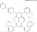
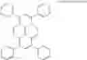
In order to achieve the object, this document provides a pyrene based electron transport compound having chemical formula 1.
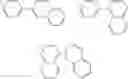
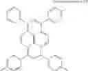
Pyrene based compound of chemical formula 1-1 is a very important compound among hydrocarbons. In the pyrene based compound, carbons are numbered clockwise starting with a carbon having a substituent A-C. Accordingly, an electron transport compound according to an embodiment of this document comprises a pyrene based compound in which A-C is bonded to carbon 1 and 6, and B is bonded to carbon 3 and 8. The substituents A, B, and C may be substituted or not substituted.
The electron transport compound is a compound that injects an electron from a cathode to other layer or transports an injected electron to other layers. For example, in organic light emitting device, an electron transport compound is a compound that may be a material of an electron injecting layer, an electron transport layer, or an electron injecting and transport layer in which the electron injecting layer and the electron transport layer are mixed.
In this document, the electron injecting and transport layer is used to generally designate layers, which are related to injecting and transporting of an electron, such as an electron injecting layer, an electron transport layer, or an electron injecting and transport layer in which the electron injecting layer and the electron transport layer are mixed.
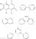
A that is substituted or is not substituted may be selected from a group consisting of pyridinyl, quinolinyl, isoquinolinyl, quinoxalinyl, bipyridinyl, terpyridinyl, and phenanthrolinyl.
Further, B and C that are substituted or are not substituted may be selected from a group consisting of phenyl, biphenyl, naphthyl, fluorenyl, terphenyl, phenanthrolinyl, phenanthryl, and anthryl.
When the A, B, and C are substituted, a substituent of the A, B, and C may be selected from a group consisting of aryl, alkyl, aryloxy, alkoxy, allylamino, alkylamino, halogen, and cyano.
Further, when the A, B, and C are substituted, a substituent of the A, B, and C may be selected from a group consisting of phenyl, biphenyl, triphenylmethyl, phenylethylidene, diphenylethylidene, phenylmethylidyne, phenoxy, tolyoxy, methyl, ethyl, propyl, i-propyl, t-butyl, cyclohexyl, diphenylamino, morpholine, methoxy, ethoxy, propoxy, butoxy, dimethylamino, diphenylamino, fluorine, and chlorine.
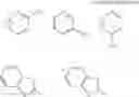
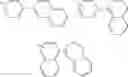
The A that is substituted or is not substituted is given by chemical formulas 1-2 and 1-3.
where any one of R1, R2, R3, R4, R5, and R6 is CH3, and the remaining ones are H.
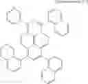
Similarly, the B and C that are substituted or not substituted are given by chemical formula 1-4.
Various forms of electron transport compounds can be formed by combining the pyrene based electron transport compound of chemical formula 1-1 with substituents of chemical formulas 1-2 to 1-4. The electron transport compounds can be easily selected by those skilled in the art according to necessity of brightness, color purity, or a driving voltage.
This document provides organic light emitting device having the electron injecting and transport layer comprising the electron transport compound described above. The electron injecting and transport layer may be one or both of an electron injecting layer or an electron transport layer. The electron injecting and transport layer may be formed between an organic light emitting layer and a cathode. The electron injecting and transport layer may have a different layer position when participating in injecting and transporting of an electron as described above.
Below, synthesis examples of some compounds of the pyrene based electron transport compounds of chemical formula 1-1 are described. Only synthesis examples of some compounds are described, but synthesis examples of other pyrene based electron transport compounds of chemical formula 1-1 are similar to these synthesis examples, the synthesis examples can be easily executed by those skilled in the art, and thus descriptions thereof will be omitted.
SYNTHESIS EXAMPLE
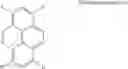
1,5-di(4-(3′-pyridine)phenyl)-3,6-diphenylpyrene among electron transport compounds of an electron injecting and transport layer of organic light emitting device according to a first embodiment of this document is synthesized as follows.
(1) Synthesis of 1,5-di(4-(3′-pyridine)-phenyl)pyrene
8.3 g (0.0416 mol) of 4-(3′-pyridine)phenyl boronic acid and 5 g (0.0139 mol) of 1,5-dibromopyrene were put in 100 mL of anhydrous THF and they were stirred in a dried three neck round bottom flask.
1.0 g of tetrakis(triphenylphosphine)palladium(0) and 15 g of potassium carbonate were melted in 100 mL of H2O and added to the flask. Then they were stirred for 24 hours in a bath of 1000 and when a reaction was ended, THF was removed from a reaction mixture.
Thereafter, the reaction mixture was extracted using dichloromethane and water and distilled under a reduced pressure, then the distilled mixture was purified by passing through a silica gel column. The purified mixture was distilled under a reduced pressure again. The purified and distilled mixture was recrystallized using dichloromethane and methanol and filtered. Then 1,5-di(4-(3′-pyridine)-phenyl)pyrene was obtained.
(2) Synthesis of 3,6-dibromo-1,5-di(4-(3′-pyridine)-phenyl)pyrene
1,5-di(4-(3′-pyridine)-phenyl)pyrene was put in 80 mL of acetic acid and they were stirred in a dried three neck round bottom flask. After 1.9 g (0.0118 mol) of bromine (Br2) was added to the reaction mixture at a room temperature and when a reaction was ended, filtering was performed. By washing and then drying the reaction mixture with excessive distilled water, 3,6-dibromo-1,5-di(4-(3′-pyridine)-phenyl)pyrene was obtained.
(3) Synthesis of 1,5-di(4-(3′-pyridine)phenyl)-3,6-diphenylpyrene
3 g (0.0045 mol) of 3,6-dibromo-1,5-di(4-(3′-pyridine)-phenyl)pyrene and 1.65 g (0.0135 mol) of phenyl boronic acid were put in 80 mL of anhydrous THF and they are stirred in a dried three neck round bottom flask.
0.4 g of tetrakis(triphenylphosphine)palladium(0) and 10 g of potassium carbonate were melted in 80 mL of H2O and added to the three neck round bottom flask. Then the reaction mixture was stirred for 24 hours in a bath of 100□ and when a reaction was ended, THF was removed from the reaction mixture.
Thereafter, the reaction mixture was extracted using dichloromethane and water and distilled under a reduced pressure. The distilled mixture was purified by passing through a silica gel column, then distilled under a reduced pressure again. The purified and distilled mixture was recrystallized using dichloromethane and methanol and filtered. Then, 1,5-di(4-(3′-pyridine)phenyl)-3,6-diphenylpyrene, which is a final product was obtained.
[Brightness, Color Purity and Driving Voltage Test 1]
In order to confirm brightness characteristic and color purity of organic light emitting device according to an embodiment of this document, conventional organic light emitting device and organic light emitting device according to an embodiment of this document were manufactured and brightness, color purity, and a driving voltage thereof were measured under the same condition.
In other words, organic light emitting device according to an embodiment of this document was manufactured using the electron transport compound synthesized in the synthesis example and conventional organic light emitting device was manufactured using a conventional material in the electron injecting and transport layer. Then brightness, color purity, and a driving voltage thereof were measured under the same condition.
In examples, although some electron transport compounds according to embodiments of this document are described, an organic light emitting device manufactured using other pyrene based electron transport compound of chemical formula 1-1 may show the same or similar result as examples. The result may be expected by those skilled in the art and thus descriptions of other compounds will be omitted.
(1) A COMPARATIVE EXAMPLE
Conventional Organic Light Emitting Device
ITO glass was washed after being patterned so that a light emitting area thereof became 3 mm×3 mm. After the substrate was mounted in a vacuum chamber, a hole injecting layer/a hole transport layer/a green organic emitting layer (host+dopant)/an electron injecting and transport layer/cathode (CuPc(650 Å)/NPD(400 Å)/Alq3(200 Å)+GD−1(1%) (50 Å)/Alq3(350 Å)/LiF(5 Å)/Al(1000 Å)) were formed on ITO in 1.0×10⁻⁶ torr.
When current of 0.9 mA was applied to the device, brightness was 1251 cd/m2, a driving voltage was 6.5V, and a value of a color coordinate CIE was x=0.307 and y=0.612.
(2) EXAMPLE 1
ITO glass was washed after being patterned so that a light emitting area thereof became 3 mm×3 mm. After the substrate was mounted in a vacuum chamber, a hole injecting layer/a hole transport layer/a green organic emitting layer (host+dopant)/an electron injecting and transport layer/cathode (CuPc(650 Å)/NPD(400 Å)/Alq3(200 Å)+GD-1 (1%) (50 Å)/PA-1(350 Å)/LiF (5 Å)/Al (1000 Å)) were formed on ITO in 1.0×10⁻⁶ torr. PA-1 is a pyrene based electron transport compound of chemical formula 1-6.
When current of 0.9 mA was applied to the device, brightness was 2452 cd/m2, a driving voltage was 4.7V, and a value of a color coordinate CIE was x=0.301 and y=0.606.
(3) EXAMPLE 2
ITO glass was washed after being patterned so that a light emitting area thereof became 3 mm×3 mm. After the substrate was mounted in a vacuum chamber, a hole injecting layer/a hole transport layer/a green organic emitting layer (host+dopant)/an electron injecting and transport layer/cathode CuPc(650 Å)/NPD(400 Å)/Alq3(200 Å)+GD-1(1%) (50 Å)/PA-2(350 Å)/LiF(5 Å)/Al(1000 Å) were formed on ITO in 1.0×10⁻⁶ torr. PA-2 is a pyrene based electron transport compound of chemical formula 1-7.
When current of 0.9 mA was applied to the device, brightness was 2328 cd/m2, a driving voltage was 5.0V, and a value of a color coordinate CIE was x=0.302 and y=0.612.
(4) EXAMPLE 3
ITO glass was washed after being patterned so that a light emitting area thereof became 3 mm×3 mm. After the substrate was mounted in a vacuum chamber, a hole injecting layer/a hole transport layer/a green organic emitting layer (host+dopant)/an electron injecting and transport layer/cathode (CuPc(650 Å)/NPD(400 Å)/Alq3(200 Å)+GD-1(1%)(50 Å)/PB-1(350 Å)/LiF(5 Å)/Al(1000 Å)) were formed on ITO in 1.0×10⁻⁶ torr. PB-1 is a pyrene based electron transport compound of chemical formula 1-8.
When current of 0.9 mA was applied to the device, brightness was 2751 cd/m2, a driving voltage was 5.1V, and a value of a color coordinate CIE was x=0.298 and y=0.610.
(5) EXAMPLE 4
ITO glass was washed after being patterned so that a light emitting area thereof became 3 mm×3 mm. After the substrate was mounted in a vacuum chamber, a hole injecting layer/a hole transport layer/a green organic emitting layer (host+dopant)/an electron injecting and transport layer/cathode (CuPc(650 Å)/NPD(400 Å)/Alq3(200 Å)+GD-1 (1%)(50 Å)/PC-1(350 Å)/LiF(5 Å)/Al(1000 Å)) were formed on ITO in 1.0×10⁻⁶ torr PC-1 is a pyrene based electron transport compound of chemical formula 1-9.
When current of 0.9 mA was applied to the device, brightness was 2617 cd/m2, a driving voltage was 5.3V, and a value of a color coordinate CIE was x=0.307 and y=0.612.
(6) EXAMPLE 5
ITO glass was washed after being patterned so that a light emitting area thereof became 3 mm×3 mm. After the substrate was mounted in a vacuum chamber, a hole injecting layer/a hole transport layer/a green organic emitting layer (host+dopant)/an electron injecting and transport layer/cathode (CuPc(650 Å)/NPD(400 Å)/Alq3(200 Å)+GD-1 (1%) (50 Å)/PE-1(350 Å)/LiF(5 Å)/Al(1000 Å)) were formed on ITO in 1.0×10⁻⁶ torr. PE-1 is a pyrene based electron transport compound of chemical formula 1-10.
When current of 0.9 mA was applied to the device, brightness was 2472 cd/m2, a driving voltage was 5.4V, and a value of a color coordinate CIE was x=0.31 and y=0.614.
(7) EXAMPLE 6
Organic Light Emitting Device According to a Sixth Embodiment of this Document
ITO glass was washed after being patterned so that a light emitting area thereof became 3 mm×3 mm. After the substrate was mounted in a vacuum chamber, a hole injecting layer/a hole transport layer/a green organic emitting layer (host+dopant)/an electron injecting and transport layer/cathode (CuPc(650 Å)/NPD(400 Å)/Alq3(200 Å)+GD-1 (1%) (50 Å)/PF-1(350 Å)/LiF(5 Å)/Al(1000 Å)) were formed on ITO in 1.0×10⁻⁶ torr. PF-1 is a pyrene based electron transport compound of chemical formula 1-11.
When current of 0.9 mA was applied to the device, brightness was 2217 cd/m2, a driving voltage was 5.5V, and a value of a color coordinate CIE was x=0.302 and y=0.610.
(8) EXAMPLE 7
Organic Light Emitting Device According to a Seventh Embodiment of this Document
ITO glass was washed after being patterned so that a light emitting area thereof became 3 mm×3 mm. After the substrate was mounted in a vacuum chamber, a hole injecting layer/a hole transport layer/a green organic emitting layer (host+dopant)/an electron injecting and transport layer/cathode (CuPc(650 Å)/NPD(400 Å)/Alq3(200 Å)+GD-1 (1%) (50 Å)/PK-1(350 Å)/LiF(5 Å)/Al(1000 Å)) were formed on ITO in 1.0×10⁻⁶ torr. PK-1 is a pyrene based electron transport compound of chemical formula 1-12.
When current of 0.9 mA was applied to the device, brightness was 2830 cd/m2, a driving voltage was 5.0V, and a value of a color coordinate CIE was x=0.297 and y=0.609.
As can be seen in the comparative example and examples, when organic light emitting device according to embodiments of this document comprise pyrene based electron transport compound of chemical formula 1-1 described above in an electron injecting and transport layer, a value of a color coordinate CIE was x=0.397 to 0.307 and y=0.606 to 0.612, and thus it can be seen that an electron injecting and transport layer performs its own function very effectively.
Referring to Table 1, brightness of organic light emitting device according to embodiments of this document improves by minimum 77.2% (the sixth embodiment) and maximum 26% (the seventh embodiment), compared to brightness of conventional organic light emitting device. It can be seen that a driving voltage of organic light emitting device according to embodiments of this document was decreased to 4.7V to 5.5V, compared to a driving voltage of conventional organic light emitting device.
| TABLE 1 | ||
| brightness | driving voltage | |
| Comparative example | 1251 cd/m2 | 6.5 V | |
| Example 1 | 2452 cd/m2 | 4.7 V | |
| Example 2 | 2328 cd/m2 | 5.0 V | |
| Example 3 | 2751 cd/m2 | 5.1 V | |
| Example 4 | 2617 cd/m2 | 5.3 V | |
| Example 5 | 2472 cd/m2 | 5.4 V | |
| Example 6 | 2217 cd/m2 | 5.5 V | |
| Example 7 | 2830 cd/m2 | 5.0 V | |
Embodiment 2
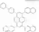
In order to achieve the object, this document provides a pyrene based electron transport compound having chemical formula 2-1.
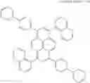
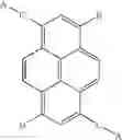
Pyrene based compound of chemical formula 2-1 is a very important compound among hydrocarbons. In the pyrene based compound, carbons are numbered clockwise starting with a carbon having a substituent A-C. Accordingly, an electron transport compound according to an embodiment of this document comprises a pyrene based compound in which A-C is bonded to carbon 1 and B is bonded to carbon 3, 6 and 8. The substituents A, B, and C may be substituted or not substituted.
The electron transport compound is a compound that injects an electron from a cathode to other layer or transports an injected electron to other layers. For example, in organic light emitting device, an electron transport compound is a compound that may be a material of an electron injecting layer, an electron transport layer, or an electron injecting and transport layer in which the electron injecting layer and the electron transport layer are mixed.
In this document, the electron injecting and transport layer is used to generally designate layers, which are related to injecting and transporting of an electron, such as an electron injecting layer, an electron transport layer, or an electron injecting and transport layer in which the electron injecting layer and the electron transport layer are mixed.
A that is substituted or is not substituted may be selected from a group consisting of pyridinyl, quinolinyl, isoquinolinyl, quinoxalinyl, bipyridinyl, terpyridinyl, and phenanthrolinyl.
Further, B and C that are substituted or are not substituted may be selected from a group consisting of phenyl, biphenyl, naphthyl, fluorenyl, terphenyl, phenanthrolinyl, phenanthryl, and anthryl.
When the A, B, and C are substituted, a substituent of the A, B, and C may be selected from a group consisting of aryl, alkyl, aryloxy, alkoxy, allylamino, alkylamino, halogen, and cyano.
Further, when the A, B, and C are substituted, a substituent of the A, B, and C may be selected from a group consisting of phenyl, biphenyl, triphenylmethyl, phenylethylidene, diphenylethylidene, phenylmethylidyne, phenoxy, tolyoxy, methyl, ethyl, propyl, i-propyl, t-butyl, cyclohexyl, diphenylamino, morpholine, methoxy, ethoxy, propoxy, butoxy, dimethylamino, diphenylamino, fluorine, and chlorine.
The A that is substituted or is not substituted is given by chemical formulas 2-2 and 2-3.
where any one of R1, R2, R3, R4, R5, and R6 is CH3, and the remaining ones are H.
Similarly, the B and C that are substituted or not substituted are given by chemical formula 2-4.
Various forms of electron transport compounds can be formed by combining the pyrene based electron transport compound of chemical formula 2-1 with substituents of chemical formulas 2-2 to 2-4. The electron transport compounds can be easily selected from organic light emitting device such as organic light emitting device by those skilled in the art according to necessity of brightness, color purity, or a driving voltage.
This document provides organic light emitting device having the electron injecting and transport layer comprising the electron transport compound described above. The electron injecting and transport layer may be one or both of an electron injecting layer or an electron transport layer. The electron injecting and transport layer may be formed between an organic or inorganic light emitting layer and a cathode. The electron injecting and transport layer may have a different layer position when participating in injecting and transporting of an electron as described above.
Below, synthesis examples of some compounds of the pyrene based electron transport compounds of chemical formula 2-1 are described. Only synthesis examples of some compounds are described, but synthesis examples of other pyrene based electron transport compounds of chemical formula 2-1 are similar to these synthesis examples, the synthesis examples can be executed by those skilled in the art, and thus descriptions thereof will be omitted.
SYNTHESIS EXAMPLE
1-(4-(3′-pyridine)phenyl)-3,6,8-triphenylpyrene among electron transport compounds of an electron injecting and transport layer of organic light emitting device according to an embodiment of this document is synthesized as follows.
(1) Synthesis of 1-(4-(3′-pyridine)phenyl)pyrene
5.31 g (0.0267 mol) of 4-(3′-pyridine) phenyl boronic acid and 5 g (0.0178 mol) of 1-bromopyrene were put in 100 mL of anhydrous THF and they were stirred in a dried three neck round bottom flask.
1.0 g of tetrakis(triphenylphosphine)palladium(0) and 15 g of potassium carbonate were melted in 100 mL of H2O and added to the flask. Then they were stirred for 24 hours in a bath of 100□. When a reaction was ended, THF was removed from a reaction mixture.
Thereafter, the reaction mixture was extracted using dichloromethane and water and distilled under a reduced pressure then the distilled mixture was purified by passing through a silica gel column. The purified mixture was distilled under a reduced pressure again. The purified and distilled mixture was recrystallized using dichloromethane and methanol and filtered. Then 1-(4-(3′-pyridine)-phenyl)pyrene was obtained.
(2) Synthesis of 1-(4-(3′-pyridine)-phenyl)-3,6,8-tribromopyrene
3 g (0.0084 mol) of 1-(4-(3′-pyridine)-phenyl)pyrene was put in 80 mL of acetic acid and they were stirred in a dried three neck round bottom flask. After 4.0 g (0.0252 mol) of bromine (Br2) was added to the reaction mixture at a room temperature and when a reaction was ended, filtering was performed. By washing and then drying the reaction mixture with excessive distilled water, 1-(4-(3′-pyridine)-phenyl)-3,6,8-tribrmopyrene was obtained.
(3) Synthesis of 1-(4-(3′-pyridine)phenyl)-3,6,8-triphenylpyrene
3 g (0.00506 mol) of 1-(4-(3′-pyridine)-phenyl)-3,6,8-tribromophylene and 2.47 g (0.0202 mol) of phenyl boronic acid were put in 80 mL of anhydrous THF and they were stirred in a dried three neck round bottom flask.
0.4 g of (tetrakis(triphenylphosphine)palladium)(O) and 10 g of potassium carbonate were melted in 80 mL of H2O and added to the flask. Then they were stirred for 24 hours in a bath of 100□. When a reaction was ended, THF was removed from a reaction mixture.
Thereafter, the reaction mixture was extracted using dichloromethane and water and distilled under a reduced pressure then the distilled mixture was purified by passing through a silica gel column. The purified mixture was distilled under a reduced pressure again. The purified and distilled mixture was recrystallized using dichloromethane and methanol and filtered. Then 1-(4-(3′-pyridine)-phenyl)-3,6,8-triphenylenepyrene was obtained.
[Brightness, Color Purity and Driving Voltage Test 2]
In order to confirm brightness characteristic and color purity of organic light emitting device according to an embodiment of this document, conventional organic light emitting device and organic light emitting device according to an embodiment of this document were manufactured and brightness, color purity, and a driving voltage thereof were measured under the same condition.
In other words, organic light emitting device according to an embodiment of this document was manufactured using the electron transport compound synthesized in the synthesis example and conventional organic light emitting device was manufactured using a conventional material in the electron injecting and transport layer. Then brightness, color purity, and a driving voltage thereof were measured under the same condition.
In examples, although some electron transport compounds according to embodiments of this document are described, an organic light emitting device manufactured using other pyrene based electron transport compound of chemical formula 1-1 may show the same or similar result as examples. The result may be expected by those skilled in the art and thus descriptions of other compounds will be omitted.
(1) A COMPARATIVE EXAMPLE
Conventional Organic Light Emitting Device
ITO glass was washed after being patterned so that a light emitting area thereof became 3 mm×3 mm. After the substrate was mounted in a vacuum chamber, a hole injecting layer/a hole transport layer/a green organic emitting layer (host+dopant)/an electron injecting and transport layer/cathode (CuPc(650 Å)/NPD(400 Å)/Alq3(200 Å)+GD-1(1%) (50 Å)/Alq3(350 Å)/LiF(5 Å)/Al(1000 Å)) were formed on ITO in 1.0×10⁻⁶ torr.
When current of 0.9 mA was applied to the device, brightness was 1251 cd/m2, a driving voltage was 6.5V, and a value of a color coordinate CIE was x=0.307 and y=0.612.
(2) EXAMPLE 1
ITO glass was washed after being patterned so that a light emitting area thereof became 3 mm×3 mm. After the substrate was mounted in a vacuum chamber, a hole injecting layer/a hole transport layer/a green organic emitting layer (host+dopant)/an electron injecting and transport layer/cathode (CuPc(650 Å)/NPD(400 Å)/Alq3(200 Å)+GD-1 (1%) (50 Å)/TPA-1(350 Å)/LiF(5 Å)/Al(1000 Å)) were formed on ITO in 1.0×10⁻⁶ torr. TPA-1 is an electron transport compound of 1-(4-(3′-pyridine)phenyl)-3,6,8-trhenylpyrene of chemical formula 2-6 in which A is pyridine and B and C are phenyl.
When current of 0.9 mA was applied to the device, brightness was 2511/m2, a driving voltage was 5.1V, and a value of a color coordinate CIE was x=0.301 and y=0.610.
(3) EXAMPLE 2
ITO glass was washed after being patterned so that a light emitting area thereof became 3 mm×3 mm. After the substrate was mounted in a vacuum chamber, a hole injecting layer/a hole transport layer/a green organic emitting layer (host+dopant)/an electron injecting and transport layer/cathode CuPc(650 Å)/NPD(400 Å)/Alq3(200 Å)+GD-1 (1%)(50 Å)/TPB-1(350 Å)/LiF(5 Å)/Al(1000 Å) were formed on ITO in 1.0×10⁻⁶ torr. TPB-8 is a pyrene based electron transport compound of chemical formula 2-7 in which A is pyridine, B is biphenyl and C is phenyl.
When current of 0.9 mA was applied to the device, brightness was 2830 cd/m2, a driving voltage was 5.1V, and a value of a color coordinate CIE was x=0.300 and y=0.607.
(4) EXAMPLE 3
ITO glass was washed after being patterned so that a light emitting area thereof became 3 mm×3 mm. After the substrate was mounted in a vacuum chamber, a hole injecting layer/a hole transport layer/a green organic emitting layer (host+dopant)/an electron injecting and transport layer/cathode (CuPc(650 Å)/NPD(400 Å)/Alq3(200 Å)+GD-1(1%)(50 Å)/TPC-1(350 Å)/LiF(5 Å)/Al(1000 Å)) were formed on ITO in 1.0×10⁻⁶ torr. TPC-1 is a pyrene based electron transport compound of chemical formula 2-8.
When current of 0.9 mA was applied to the device, brightness was 2770 cd/m2, a driving voltage was 5.3V, and a value of a color coordinate CIE was x=0.302 and y=0.611.
(5) EXAMPLE 4
ITO glass was washed after being patterned so that a light emitting area thereof became 3 mm×3 mm. After the substrate was mounted in a vacuum chamber, a hole injecting layer/a hole transport layer/a green organic emitting layer (host+dopant)/an electron injecting and transport layer/cathode (CuPc(650 Å)/NPD(400 Å)/Alq3(200 Å)+GD-1(1%)(50 Å)/TPE-1(350 Å)/LiF(5 Å)/Al(1000 Å)) were formed on ITO in 1.0×10⁻⁶ torr TPE-1 is a pyrene based electron transport compound of chemical formula 2-9.
When current of 0.9 mA was applied to the device, brightness was 2069 cd/m2, a driving voltage was 5.5V, and a value of a color coordinate CIE was x=0.304 and y=0.614.
(6) EXAMPLE 5
ITO glass was washed after being patterned so that a light emitting area thereof became 3 mm×3 mm. After the substrate was mounted in a vacuum chamber, a hole injecting layer/a hole transport layer/a green organic emitting layer (host+dopant)/an electron injecting and transport layer/cathode (CuPc(650 Å)/NPD(400 Å)/Alq3(200 Å)+GD-1(1%) (50 Å)/TPF-1(350 Å)/LiF(5 Å)/Al(1000 Å)) were formed on ITO in 1.0×10⁻⁶ torr. TPF-1 is a pyrene based electron transport compound of chemical formula 2-10.
When current of 0.9 mA was applied to the device, brightness was 2466 cd/m2, a driving voltage was 5.7V, and a value of a color coordinate CIE was x=0.300 and y=0.610.
(7) EXAMPLE 6
ITO glass was washed after being patterned so that a light emitting area thereof became 3 mm×3 mm. After the substrate was mounted in a vacuum chamber, a hole injecting layer/a hole transport layer/a green organic emitting layer (host+dopant)/an electron injecting and transport layer/cathode (CuPc(650 Å)/NPD(400 Å)/Alq3(200 Å)+GD-1(1%) (50 Å)/TPK-1(350 Å)/LiF(5 Å)/Al(1000 Å)) were formed on ITO in 1.0×10⁻⁶ torr. TPK-1 is a pyrene based electron transport compound of chemical formula 2-11.
When current of 0.9 mA was applied to the device, brightness was 2750 cd/m2, a driving voltage was 5.2V, and a value of a color coordinate CIE was x=0.302 and y=0.610.
As can be seen in a comparative experiment example, when organic light emitting device according to embodiments of this document use the pyrene based electron transport compound of chemical formula 2-1 described above in an electron injecting and transport layer, a value of a color coordinate CIE was x=0.300 to 0.307 and y=0.607 to 0.614, and thus it can be seen that an electron injecting and transport layer performs its own function.
As can be seen in Table 2, brightness of organic light emitting device according to embodiments of this document improves by minimum 77.2% (the sixth embodiment) and maximum 26% (the seventh embodiment), compared to brightness of conventional organic light emitting device. It can be seen that a driving voltage of organic light emitting device according to embodiments of this document was decreased to 5.1V to 5.7V.
| TABLE 2 | ||
| brightness | driving voltage | |
| Comparative example | 1251 cd/m2 | 6.5 V | |
| Example 1 | 2511 cd/m2 | 5.1 V | |
| Example 2 | 2830 cd/m2 | 5.1 V | |
| Example 3 | 2770 cd/m2 | 5.3 V | |
| Example 4 | 2069 cd/m2 | 5.5 V | |
| Example 5 | 2466 cd/m2 | 5.7 V | |
| Example 6 | 2750 cd/m2 | 5.2 V | |
Embodiment 3
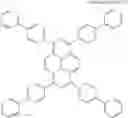
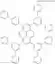
In order to achieve the object, this document provides a pyrene based electron transport compound having chemical formula 3-1.
Pyrene based compound of chemical formula 3-1 is a very important compound among hydrocarbons. In the pyrene based compound, carbons are numbered clockwise starting with a carbon having a substituent A. Accordingly, an electron transport compound according to an embodiment of this document comprises a pyrene based compound in which A is bonded to carbon 1, and B is bonded to carbon 3, 6 and 8. The substituents A and B may be substituted or not substituted.
The electron transport compound is a compound that injects an electron from a cathode to other layer or transports an injected electron to other layers. For example, in organic light emitting device, an electron transport compound is a compound that may be a material of an electron injecting layer, an electron transport layer, or an electron injecting and transport layer in which the electron injecting layer and the electron transport layer are mixed.
In this document, an electron injecting and transport layer is used to generally designate layers, which are related to injecting and transporting of an electron, such as an electron injecting layer, an electron transport layer, or an electron injecting and transport layer in which the electron injecting layer and the electron transport layer are mixed.
A that is substituted or is not substituted may be selected from a group consisting of pyridinyl, quinolinyl, isoquinolinyl, quinoxalinyl, bipyridinyl, terpyridinyl, and phenanthrolinyl.
Further, B and C that are substituted or are not substituted may be selected from a group consisting of phenyl, biphenyl, naphthyl, fluorenyl, terphenyl, methyl, ethyl, propyl, i-propyl, halogen, phenanthrolinyl, phenanthryl, and anthryl.
When the A and B are substituted, a substituent of the A and B may be selected from a group consisting of aryl, alkyl, aryloxy, alkoxy, allylamino, alkylamino, halogen, and cyano.
Further, when the A and B are substituted, a substituent of the A and B may be selected from a group consisting of phenyl, biphenyl, triphenylmethyl, phenylethylidene, diphenylethylidene, phenylmethylidyne, phenoxy, tolyoxy, methyl, ethyl, propyl, i-propyl, t-butyl, cyclohexyl, diphenylamino, morpholine, methoxy, ethoxy, propoxy, butoxy, dimethylamino, diphenylamino, fluorine, and chlorine.
The A that is substituted or is not substituted is given by chemical formulas 3-2 and 3-3.
where any one of R1, R2, R3, R4, R5, and R6 is CH3, and the remaining ones are H.
Similarly, the B that is substituted or not substituted is given by chemical formula 3-4.
Various forms of electron transport compounds can be formed by combining the pyrene based electron transport compound of chemical formula 3-1 with substituents of chemical formulas 3-2 to 3-4. The electron transport compounds can be easily selected by those skilled in the art according to necessity of brightness, color purity, or a driving voltage.
This document provides organic light emitting device having the electron injecting and transport layer comprising the electron transport compound described above. The electron injecting and transport layer may be one or both of an electron injecting layer or an electron transport layer. The electron injecting and transport layer may be formed between an organic or inorganic light emitting layer and a cathode. The electron injecting and transport layer may have a different layer position when participating in injecting and transporting of an electron as described above.
Below, synthesis examples of some compounds of the pyrene based electron transport compounds of chemical formula 3-1 are described. Only synthesis examples of some compounds are described, but synthesis examples of other pyrene based electron transport compounds of chemical formula 3-1 are similar to these synthesis examples, the synthesis examples can be executed by those skilled in the art, and thus descriptions thereof will be omitted.
SYNTHESIS EXAMPLE
1-(3′-pyridine)-3,6,8-triphenyl-pyrene among electron transport compounds of an electron injecting and transport layer of organic light emitting device according to an embodiment of this document is synthesized as follows.
Synthesis of 1-(3′-pyridine)pyrene
6.56 g (0.053 mol) of pyridinyl boronic acid and 5 g (0.0178 mol) of 1-bromopyrene were put in 100 mL of anhydrous THF and they were stirred in a dried three neck round bottom flask.
0.9 g of (tetrakis(triphenylphosphine)palladium)(0) and 15 g of potassium carbonate were melted in 100 mL of H2O added to the flask. Then they were stirred for 24 hours in a bath of 100□ and then when a reaction was ended, THF was removed from the reaction mixture.
Thereafter, the reaction mixture was extracted using dichloromethane and water and distilled under a reduced pressure, then the distilled mixture was purified by passing through a silica gel column. The purified mixture was distilled under a reduced pressure again. The purified and distilled mixture was recrystallized using dichloromethane and methanol and filtered. Then 1-(3′-pyridine)pyrene was obtained.
(2) Synthesis of 1-(3′-pyridine)-3,4,6-tribromopyrene
3 g (0.0107 mol) of 1-(3′-pyridine)pyrene was put in 80 mL of acetic acid and was stirred in a dried three neck round bottom flask. After 5.15 g (0.0322 mol) of bromine (Br2) was added to the reaction mixture at a room temperature and when a reaction was ended, filtering was performed. By washing and then drying the reaction mixture with excessive distilled water, 1-(3′-pyridine)-3,6,8,-tribromopyrene was obtained.
(3) Synthesis of 1-(3′-pyridine)-3,6,8,-triphenyl-pyrene
3 g (0.00581 mol) of 1-(3′-pyridine)-3,6,8,-tribromopyrene and 2.83 g (0.0232 mol) of phenyl boronic acid were put in 80 mL of anhydrous THF and they were stirred in a dried three neck round bottom flask.
0.5 g of (tetrakis(triphenylphosphine)palladium)(0) and 10 g of potassium carbonate were melted in 80 mL of H2O and H2O and added to the flask. Then they were stirred for 24 hours in a bath of 100□ and when a reaction was ended, THF was removed from the reaction mixture.
Thereafter, the reaction mixture was extracted using dichloromethane and water and distilled under a reduced pressure, then distilled mixture was purified by passing through a silica gel column. The purified mixture was distilled under a reduced pressure again. The purified and distilled mixture was recrystallized using dichloromethane and methanol and filtered. 1-(3′-pyridine)-3,6,8-triphenyl-pyrene, which is a final product was obtained.
[Brightness, Color Purity and Driving Voltage Test 3]
In order to confirm brightness characteristic and color purity of organic light emitting device according to an embodiment of this document, conventional organic light emitting device and organic light emitting device according to an embodiment of this document were manufactured and brightness, color purity, and a driving voltage thereof were measured under the same condition.
In other words, organic light emitting device according to an embodiment of this document was manufactured using the electron transport compound synthesized in the synthesis example and conventional organic light emitting device was manufactured using a conventional material in the electron injecting and transport layer. Then brightness, color purity, and a driving voltage thereof were measured under the same condition.
In examples, although some electron transport compounds according to embodiments of this document are described, an organic light emitting device manufactured using other pyrene based electron transport compound of chemical formula 1-1 may show the same or similar result as examples. The result may be expected by those skilled in the art and thus descriptions of other compounds will be omitted.
(1) A COMPARATIVE EXAMPLE
Conventional Organic Light Emitting Device
ITO glass was washed after being patterned so that a light emitting area thereof became 3 mm×3 mm. After the substrate was mounted in a vacuum chamber, a hole injecting layer/hole transport layer/green color organic emitting layer (host+dopant)/electron injecting and transport layer/cathode (CuPc(650 Å)/NPD(400 Å)/Alq3(200 Å)+GD-1(1%) (50 Å)/Alq3(350 Å)/LiF(5 Å)/Al(1000 Å)) was formed on ITO in 1.0×10⁻⁶ torr.
When current of 0.9 mA was applied to the device, brightness was 1251 cd/m2, a driving voltage was 6.5V, and a value of a color coordinate CIE was x=0.307 and y=0.612.
(2) EXAMPLE 1
ITO glass was washed after being patterned so that a light emitting area thereof became 3 mm×3 mm. After the substrate was mounted in a vacuum chamber, a hole injecting layer/a hole transport layer/a green organic emitting layer (host+dopant)/an electron injecting and transport layer/cathode (CuPc(650 Å)/NPD(400 Å)/Alq3(200 Å)+GD-1 (1%) (50 Å)/TA-8(350 Å)/LiF(5 Å)/Al(1000 Å)) were formed on ITO in 1×10⁻⁶ torr. TA-8 is an electron transport compound of 1-(3′-pyridine)-3,6,8-triphenyl-pyrene of chemical formula 3-6 in which A is pyridine and B and C are phenyl.
When current of 0.9 mA was applied to the device, brightness was 2403 cd/m2, a driving voltage was 5.87V, and a value of a color coordinate CIE was x=0.301 and y=0.621.
(3) EXAMPLE 2
ITO glass was washed after being patterned so that a light emitting area thereof became 3 mm×3 mm. After the substrate was mounted in a vacuum chamber, a hole injecting layer/a hole transport layer/a green organic emitting layer (host+dopant)/an electron injecting and transport layer/cathode (CuPc(650 Å)/NPD(400 Å)/Alq3(200 Å)+GD-1 (1%)(50 Å)/TB-8(350 Å)/LiF(5 Å)/Al(1000 Å)) were formed on ITO in 1.0×10⁻⁶ torr. TB-8 is a pyrene based electron transport compound of chemical formula 3-7 in which A is pyridine and B and C are phenyl.
When current of 0.9 mA was applied to the device, brightness was 2511 cd/m2, a driving voltage was 5.7V, and a value of a color coordinate CIE was x=0.301 and y=0.607.
(4) EXAMPLE 3
ITO glass was washed after being patterned so that a light emitting area thereof became 3 mm×3 mm. After the substrate was mounted in a vacuum chamber, a hole injecting layer/a hole transport layer/a green organic emitting layer (host+dopant)/an electron injecting and transport layer/cathode (CuPc(650 Å)/NPD(400 Å)/Alq3(200 Å)+GD-1 (1%) (50 Å)/TB-7(350 Å)/LiF(5 Å)/Al(1000 Å)) were formed on ITO in 1.0×10⁻⁶ torr. TB-7 is a pyrene based electron transport compound of chemical formula 3-8 in which A is pyridine and B is phenyl.
When current of 0.9 mA was applied to the device, brightness was 2398 cd/m2, a driving voltage was 5.3V, and a value of a color coordinate CIE was x=0.304 and y=0.630.
(5) EXAMPLE 4
ITO glass was washed after being patterned so that a light emitting area thereof became 3 mm×3 mm. After the substrate was mounted in a vacuum chamber, a hole injecting layer/a hole transport layer/a green organic emitting layer (host+dopant)/an electron injecting and transport layer/cathode (CuPc(650 Å)/NPD(400 Å)/Alq3(200 Å)+GD-1 (1%)(50 Å)/TC-8(350 Å)/LiF(5 Å)/Al(1000 Å)) were formed on ITO in 1.0×10⁻⁶ torr. TC-8 is a pyrene based electron transport compound of chemical formula 3-9.
When current of 0.9 mA was applied to the device, brightness was 2382 cd/m2, a driving voltage was 5.6V, and a value of a color coordinate CIE was x=0.299 and y=0.617.
(6) EXAMPLE 5
ITO glass was washed after being patterned so that a light emitting area thereof became 3 mm×3 mm. After the substrate was mounted in a vacuum chamber, a hole injecting layer/a hole transport layer/a green organic emitting layer (host+dopant)/an electron injecting and transport layer/cathode (CuPc(650 Å)/NPD(400 Å)/Alq3(200 Å)+GD-1 (1%) (50 Å)/TD-8(350 Å)/LiF(5 Å)/Al(1000 Å)) were formed on ITO in 1.0×10⁻⁶ torr. TD-8 is a pyrene based electron transport compound of chemical formula 3-10.
When current of 0.9 mA was applied to the device, brightness was 2698 cd/m2, a driving voltage was 5.5V, and a value of a color coordinate CIE was x=0.300 and y=0.638.
(7) EXAMPLE 6
ITO glass was washed after being patterned so that a light emitting area thereof became 3 mm×3 mm. After the substrate was mounted in a vacuum chamber, a hole injecting layer/a hole transport layer/a green organic emitting layer (host+dopant)/an electron injecting and transport layer/cathode (CuPc(650 Å)/NPD(400 Å)/Alq3(200 Å)+GD-1 (1%)(50 Å)/TE-8(350 Å)/LiF(5 Å)/Al(1000 Å)) were formed on ITO in 1.0×10⁻⁶ torr. TE-8 is a pyrene based electron transport compound of chemical formula 3-11.
When current of 0.9 mA was applied to the device, brightness was 2732 cd/m2, a driving voltage was 5.4V, and a value of a color coordinate CIE was x=0.300 and y=0.610.
(8) EXAMPLE 7
ITO glass was washed after being patterned so that a light emitting area thereof became 3 mm×3 mm. After the substrate was mounted in a vacuum chamber, a hole injecting layer/a hole transport layer/a green organic emitting layer (host+dopant)/an electron injecting and transport layer/cathode (CuPc(650 Å)/NPD(400 Å)/Alq3(200 Å)+GD-1 (1%)(50 Å)/TF-8(350 Å)/LiF(5 Å)/Al(1000 Å)) were formed on ITO in 1.0×10⁻⁶ torr. TF-8 is a pyrene based electron transport compound of chemical formula 3-12.
When current of 0.9 mA was applied to the device, brightness was 2287 cd/m2, a driving voltage was 5.5V, and a value of a color coordinate CIE was x=0.300 and y=0.618.
(9) EXAMPLE 8
ITO glass was washed after being patterned so that a light emitting area thereof became 3 mm×3 mm. After the substrate was mounted in a vacuum chamber a hole injecting layer/a hole transport layer/a green organic emitting layer (host+dopant)/an electron injecting and transport layer/cathode (CuPc(650 Å)/NPD(400 Å)/Alq3(200 Å)+GD-1 (1%) (50 Å)/TG-8(350 Å)/LiF(5 Å)/Al(1000 Å)) were formed on ITO in 1.0×10⁻⁶ torr. TG-8 is a pyrene based electron transport compound of chemical formula 3-13.
When current of 0.9 mA was applied to the device, brightness was 2096 cd/m2, a driving voltage was 5.7V, and a value of a color coordinate CIE was x=0.304 and y=0.629.
(10) EXAMPLE 9
ITO glass was washed after being patterned so that a light emitting area thereof became 3 mm×3 mm. After the substrate was mounted in a vacuum chamber, a hole injecting layer/a hole transport layer/a green organic emitting layer (host+dopant)/an electron injecting and transport layer/cathode (CuPc(650 Å)/NPD(400 Å)/Alq3(200 Å)+GD-1 (1%) (50 Å)/TJ-8(350 Å)/LiF(5 Å)/Al(1000 Å)) were formed on ITO in 1.0×10⁻⁶ torr. TJ-8 is a pyrene based electron transport compound of chemical formula 3-14.
When current of 0.9 mA was applied to the device, brightness was 2937 cd/m2, a driving voltage was 6.1V, and a value of a color coordinate CIE was x=0.307 and y=0.609.
As can be seen in the comparative example and examples, when organic light emitting devices according to embodiments of this document comprise the pyrene based electron transport compound of chemical formula 3-1 described above in an electron injecting and transport layer, a value of a color coordinate CIE was x=0.300 to 0.307 and y=0.600 to 0.630, and thus it can be seen that an electron injecting and transport layer performs its own function.
Referring to Table 3, brightness of organic light emitting device according to embodiments of this document improves by minimum 67.5% (the eighth embodiment) and maximum 135% (the ninth embodiment), compared to brightness of conventional organic light emitting device. It can be seen that a driving voltage of organic light emitting device according to embodiments of this document was decreased to 5.4V to 5.8V, compared to a driving voltage of conventional organic light emitting device.
| TABLE 3 | ||
| brightness | driving voltage | |
| Comparative example | 1251 cd/m2 | 6.5 V | |
| Example 1 | 2403 cd/m2 | 5.8 V | |
| Example 2 | 2511 cd/m2 | 5.7 V | |
| Example 3 | 2398 cd/m2 | 5.3 V | |
| Example 4 | 2382 cd/m2 | 5.6 V | |
| Example 5 | 2698 cd/m2 | 5.5 V | |
| Example 6 | 2732 cd/m2 | 5.4 V | |
| Example 7 | 2287 cd/m2 | 5.5 V | |
| Example 8 | 2096 cd/m2 | 5.7 V | |
| Example 9 | 2937 cd/m2 | 6.1 V | |
As described above, this document can provide an electron transport compound that has high electron transport efficiency and good deposition characteristics, prevents crystallization, and has no influence on a lifetime of diodes.
As a result, organic light emitting device according to embodiments of this document can have improved brightness and a considerably low driving voltage while performing a function as an electron injecting and transport layer, compared to conventional organic light emitting device.
Embodiments are described, but this document is not limited thereto.
The invention being thus described, it will be obvious that the same may be varied in many ways. Such variations are not to be regarded as a departure from the spirit and scope of the invention, and all such modifications as would be obvious to one skilled in the art are intended to be comprised within the scope of the following claims.
Claims
What is claimed is:1. An electron transport compound, having the following chemical formula,
wherein A that is substituted or is not substituted is selected from a group consisting of pyridinyl, quinolinyl, isoquinolinyl, quinoxalinyl, bipyridinyl, terpyridinyl, and phenanthrolinyl, and
B and C that are substituted or are not substituted are selected from a group consisting of phenyl, biphenyl, naphthyl, fluorenyl, terphenyl, phenanthrolinyl, phenanthryl, and anthryl.
2. The electron transport compound of claim 1, wherein when the A, B, and C are substituted, a substituent of the A, B, and C is selected from a group consisting of aryl, alkyl, aryloxy, alkoxy, allylamino, alkylamino, halogen, and cyano.
3. The electron transport compound of claim 1, wherein when the A, B, and C are substituted, a substituent of the A, B, and C is selected from a group consisting of phenyl, biphenyl, triphenylmethyl, phenylethylidene, diphenylethylidene, phenylmethylidyne, phenoxy, tolyoxy, methyl, ethyl, propyl, i-propyl, t-butyl, cyclohexyl, diphenylamino, morpholine, methoxy, ethoxy, propoxy, butoxy, dimethylamino, diphenylamino, fluorine, and chlorine.
4. An organic light emitting device having an electron injecting and transport layer comprising the electron transport compound of claim 1.
5. The organic light emitting device of claim 4, wherein the electron injecting and transport layer is one or both of an electron injecting layer or an electron transport layer.
6. The organic light emitting device of claim 5, wherein the organic light emitting device comprises an anode, an emitting layer comprising an organic material and a cathode, wherein the electron injecting and transport layer is formed between the emitting layer and a cathode.
7. An electron transport compound, having the following chemical formula,
wherein A that is substituted or is not substituted is selected from a group consisting of pyridinyl, quinolinyl, isoquinolinyl, quinoxalinyl, bipyridinyl, terpyridinyl, and phenanthrolinyl, and
B and C that are substituted or are not substituted are selected from a group consisting of phenyl, biphenyl, naphthyl, fluorenyl, terphenyl, phenanthrolinyl, phenanthryl, and anthryl.
8. The electron transport compound of claim 7, wherein when the A, B, and C are substituted, a substituent of the A, B, and C is selected from a group consisting of aryl, alkyl, aryloxy, alkoxy, allylamino, alkylamino, halogen, and cyano.
9. The electron transport compound of claim 7, wherein when the A, B, and C are substituted, a substituent of the A, B, and C is selected from a group consisting of phenyl, biphenyl, triphenylmethyl, phenylethylidene, diphenylethylidene, phenylmethylidyne, phenoxy, tolyoxy, methyl, ethyl, propyl, i-propyl, t-butyl, cyclohexyl, diphenylamino, morpholine, methoxy, ethoxy, propoxy, butoxy, dimethylamino, diphenylamino, fluorine, and chlorine.
10. An organic light emitting device having an electron injecting and transport layer comprising the electron transport compound of claim 7.
11. The organic light emitting device of claim 10, wherein the electron injecting and transport layer is one or both of an electron injecting layer or an electron transport layer.
12. The organic light emitting device of claim 11, wherein the organic light emitting device comprises an anode, an emitting layer comprising an organic material and a cathode, wherein the electron injecting and transport layer is formed between the emitting layer and a cathode.
13. An electron transport compound, having the following chemical formula,
wherein A that is substituted or is not substituted is selected from a group consisting of pyridinyl, quinolinyl, isoquinolinyl, quinoxalinyl, bipyridinyl, terpyridinyl, and phenanthrolinyl, and
B and C that are substituted or are not substituted are selected from a group consisting of phenyl, biphenyl, naphthyl, fluorenyl, terphenyl, methyl, ethyl, propyl, i-propyl, halogen, phenanthrolinyl, phenanthryl, and anthryl.
14. The electron transport compound of claim 13, wherein when the A and B are substituted, a substituent of the A and B is selected from a group consisting of aryl, alkyl, aryloxy, alkoxy, allylamino, alkylamino, halogen, and cyano.
15. The electron transport compound of claim 13, wherein when the A and B are substituted, a substituent of the A and B is selected from a group consisting of phenyl, biphenyl, triphenylmethyl, phenylethylidene, diphenylethylidene, phenylmethylidyne, phenoxy, tolyoxy, methyl, ethyl, propyl, i-propyl, t-butyl, cyclohexyl, diphenylamino, morpholine, methoxy, ethoxy, propoxy, butoxy, dimethylamino, diphenylamino, fluorine, and chlorine.
16. An organic light emitting device having an electron injecting and transport layer comprising the electron transport compound of claim 13.
17. The organic light emitting device of claim 16, wherein the electron injecting and transport layer is one or both of an electron injecting layer or an electron transport layer.
18. The organic light emitting device of claim 17, wherein the organic light emitting device comprises an anode, an emitting layer comprising an organic material and a cathode, wherein the electron injecting and transport layer is formed between the emitting layer and a cathode.
Images & Drawings included:


Sources:
- United States Patent and Trademark Office - verify current appl. status at the USPTO↗
Recent applications in this class:
- » 20230135170 2023-05-04
LIGHT-EMITTING DEVICE AND ELECTRONIC APPARATUS INCLUDING THE SAME - » 20230128259 2023-04-27
COMPOUND AND ORGANIC LIGHT-EMITTING DEVICE COMPRISING SAME - » 20230127217 2023-04-27
ORGANIC ELECTROLUMINESCENT ELEMENT AND ELECTRONIC DEVICE - » 20220416171 2022-12-29
ORGANIC ELECTROLUMINESCENT DEVICE CONFIGURED TO EMIT LIGHT WITH HIGH LUMINOUS EFFICIENCY - » 20220416170 2022-12-29
ORGANIC ELECTROLUMINESCENT ELEMENT AND ELECTRONIC DEVICE - » 20220393110 2022-12-08
ORGANIC ELECTROLUMINESCENCE ELEMENT, COMPOSITION, POWDER, ELECTRONIC EQUIPMENT, AND NOVEL COMPOUND - » 20220310930 2022-09-29
ORGANIC ELECTROLUMINESCENT ELEMENT EMITTING LIGHT AT HIGH LUMINOUS EFFICIENCY AND ELECTRONIC DEVICE - » 20220231228 2022-07-21
ORGANIC ELECTROLUMINESCENT DEVICE - » 20220223792 2022-07-14
ORGANIC TRANSISTOR MATERIAL AND ORGANIC TRANSISTOR - » 20220102641 2022-03-31
FUNCTIONAL MATERIALS FOR OLED APPLICATIONS
Recent applications for this Assignee:
- » 20250295016 2025-09-18
DISPLAY DEVICE - » 20250287807 2025-09-11
ORGANIC LIGHT EMITTING DISPLAY APPARATUS HAVING PIXELS OF DIFFERENT STRUCTURES - » 20250287806 2025-09-11
LIGHT EMITTING DISPLAY DEVICE - » 20250285577 2025-09-11
CLOCK GENERATOR AND DISPLAY DEVICE INCLUDING THE SAME - » 20250280721 2025-09-04
DISPLAY DEVICE - » 20250280717 2025-09-04
LIGHT EMITTING DISPLAY DEVICE - » 20250280716 2025-09-04
DISPLAY DEVICE - » 20250280709 2025-09-04
FOLDABLE DISPLAY DEVICE - » 20250280706 2025-09-04
DISPLAY DEVICE - » 20250280704 2025-09-04
DISPLAY DEVICE