Electrical connector
US20070173088A1
2007-07-26
11/656,080
2007-01-22
✅ Patent granted
US 7,435,111 B2
2008-10-14
-
-
Tulsidas C. Patel | Vladimir Imas
2027-01-22
Abstract:
An electrical connector (1) comprises an insulative housing (2) comprising plurality of passageways (25) thereon, a plurality of electrical terminals (4) received in the housing (2), a cover (5) mounted on the housing (2), wherein the cover (5) includes a number of formable members (52) extending from an inner sidewall thereof for supporting the housing (2), hence preventing the housing (2) from destroying terminals (4).
Assignee:
- Hon Hai Precision Ind. Co., Ltd. 1,929 🇹🇼 Taipei Hsien, Taiwan
Interested in similar patents?
Get notified when new applications in this technology area are published.
Classification:
H01R12/57 » CPC main
Structural associations of a plurality of mutually-insulated electrical connecting elements, specially adapted for printed circuits, e.g. printed circuit boards [PCBs], flat or ribbon cables, or like generally planar structures, e.g. terminal strips, terminal blocks; Coupling devices specially adapted for printed circuits, flat or ribbon cables, or like generally planar structures; Terminals specially adapted for contact with, or insertion into, printed circuits, flat or ribbon cables, or like generally planar structures; Fixed connections for rigid printed circuits or like structures characterised by the terminals surface mounting terminals
H01R12/7029 » CPC further
Structural associations of a plurality of mutually-insulated electrical connecting elements, specially adapted for printed circuits, e.g. printed circuit boards [PCBs], flat or ribbon cables, or like generally planar structures, e.g. terminal strips, terminal blocks; Coupling devices specially adapted for printed circuits, flat or ribbon cables, or like generally planar structures; Terminals specially adapted for contact with, or insertion into, printed circuits, flat or ribbon cables, or like generally planar structures; Coupling devices; Guiding, mounting, polarizing or locking means; Extractors; Locking or fixing a connector to a PCB; Snap means not integral with the coupling device
H01R13/04 » CPC further
Details of coupling devices of the kinds covered by groups or -; Contact members Pins or blades for co-operation with sockets
H01R13/5025 » CPC further
Details of coupling devices of the kinds covered by groups or -; Bases; Cases composed of different pieces one or more pieces being of resilient material
H01R43/0263 » CPC further
Apparatus or processes specially adapted for manufacturing, assembling, maintaining, or repairing of line connectors or current collectors or for joining electric conductors for soldered or welded connections for positioning or holding parts during soldering or welding process
H01R43/18 » CPC further
Apparatus or processes specially adapted for manufacturing, assembling, maintaining, or repairing of line connectors or current collectors or for joining electric conductors for manufacturing bases or cases for contact members
Y10S439/94 » CPC further
Electrical connectors including provision for mechanical lifting or manipulation, e.g. for vacuum lifting
H01R13/44 IPC
Details of coupling devices of the kinds covered by groups or - Means for preventing access to live contacts
Description
BACKGROUND OF THE INVENTION
1. Field of the Invention
The present invention relates to the art of electrical connectors, and more particularly to an electrical connector provided for connecting an electrical applications to a printed circuit board (PCB).
2. Description of the Prior Art
Electrical connectors are widely used in the connector industry for electrically connecting applications to printed circuit boards (PCBs) in personal computer or other consumer electrical equipments. Conventionally, an electrical connector mainly comprises an insulative housing, a multiplicity of terminals received therein, an anchoring hook, a cover mounted on the housing. The housing defines a plurality of receiving passageways for receiving terminals therein. When assembled, the terminals are inserted into the passageways of the housing, and then the cover is mounted above the housing. In this case, the electrical connector is usually positioned on the printed circuit board by a vacuum suction device vacuuming an upper surface of the cover.
However, in the electrical connector abovementioned, the cover is conventional not accurately locating on the housing, and engaged with the housing by a interferential engagement. After a long time, the engagement between the cover and the housing is prone to loose, hence the housing is easy to slide in relative to a predetermined position on the printed circuit board or drop off from the cover engaged by the vacuum suction device. In addition, for securely attaching the housing on the printed circuit board, there needs a powerful force for pressing the cover downwardly, which may destroy the terminal received therein.
Thus, there is a need to provide a new land grid connector assembly that overcomes the above-mentioned problems.
SUMMARY OF THE INVENTION
Accordingly, an object of the present invention is to provide an electrical connector able to accurately locating the cover on the housing.
To fulfill the above-mentioned object, an electrical connector in accordance with a preferred embodiment comprises an insulative housing, a plurality terminals received in the housing, a cover mounted on the housing, and the cover defines a plurality of deformable members and projected elements. In addition, the cover defines a pair of locating plate on two ends thereof and the housing defines a pair of curved locating projection.
Relative to the present technology, the electrical connector in accordance with the preferred embodiment of the invention defines a plurality of deformable members on the sidewalls of the cover, which makes the engagement of the housing and the cover more closed. Furthermore, the locating plates of the cover engage with the curved locating projections of the housing, which makes the cover accurately locating on the housing. At last, the projected elements on inner walls of the cover not only transmits the force applied on the cover effectively to the whole electrical connector but also prevents the terminals received in the housing from being crashed by the cover.
Other objects, advantages and novel features of the present invention will become more apparent from the following detailed description when taken in conjunction with the accompanying drawings, in which:
BRIEF DESCRIPTION OF THE DRAWINGS
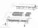
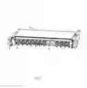
FIG. 1 is an assembled view of an electrical connector in accordance with a preferred embodiment of the present invention;
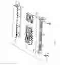
FIG. 2 is an exploded, isometric view of terminal of the electrical connector shown in FIG. 1;
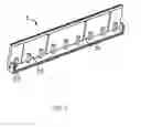
FIG. 3 is a cross-sectional view of the cover in the electrical connector of FIG. 1, in line of transverse symmetry direction.
DESCRIPTION OF PREFERRED EMBODIMENT OF THE INVENTION
Reference will now be made to the drawings to describe the present invention in detail.
Referring to FIGS. 1-2, an electrical connector 1 in accordance with the preferred embodiment of the present invention provided for electrically connecting a application to a PCB includes a generally rectangular insulative housing 2, a pair of anchoring hooks 3, a multiplicity of terminals 4 received in the housing 2 and a cover 5 attached on the housing 2.
The housing 2 includes a rectangular base portion 21. The base portion 21 defines a pair of locating portions 22 on two ends thereof which define a slant surface 221 on an end thereof respectively. In addition, the base portion 21 defines a pair of rectangular base substrates 23 on two ends thereof and each base substrate 23 defines a recess 24 on a bottom surface thereof. The base portion 21 further defines a plurality of passageways 25 for receiving the terminals 4 therein between the two locating projections 22.
The anchoring hook 3 comprises a securing portion 31 and inverted U-shaped trip portion 32. The anchoring hook 3 is used for fixing the electrical connector on the printed circuit board.
Referring to FIG. 3, the cover 5 is generally configured as U- shaped concave with sidewalls therearound and comprises a plurality of engaging element 51 and deformable members 52 on inner surfaces of the sidewalls. In addition, the cover 5 defines a pair of locating portion 53 on two ends thereof. The deformable members 51 are flushed with sidewalls of the cover 5 and the deformable members 52 extend from a bottom surface of the cover 5 to a position with a half height of the sidewall.
In assembly, the terminals 4 are firstly inserted into the passageways 25 of the housing 2. The anchoring hooks 3 are then mounted into the recesses 24 of the base substrate 23. At last, the cover 5 is attached to the housing 2 between the locating projections 22. The locating projections 22 can lead the locating portion 53 into the housing 2 by the slant surfaces 221 thereof. In addition, the engaging element 51 of the cover 5 can make the engagement between the cover 5 and the housing 2 more fittingly and reliably. In assembling electrical connector 1, the engaging element 51 abut against the upper surface of the housing 2 and the lengths of the engaging element 51 are enough to prevent the terminals 4 from contacting with the cover. The deformable members 52 are not interferentially engaged with terminals 4. The electrical connector 1 is locating on the printed circuit board by a vacuum suction device vacuuming an upper surface of the cover 5. Successively, the cover 5 is pressed downwardly toward the housing 2 by an outer force and the force transmitted by the deformable members 52 to the whole electrical connector 1 thereby the electrical connector 1 is secured mounted on the printed circuit board. At last, the anchoring hooks 3 connect the electrical connector 1 to the printed circuit board.
Although the present invention has been described with reference to a particular embodiment, it is not to be construed as being limited thereto. Various alterations and modifications can be made to the embodiment without in any way departing from the scope or spirit of the present invention as defined in the appended claims.
Claims
What is claimed is:1. An electrical connector comprising:
an insulative housing comprising plurality of passageways therein;
a plurality of electrical terminals received in the housing;
a cover mounted on the housing;
wherein the cover includes a number of deformable members extending from an inner sidewall thereof.
2. The electrical connector as claimed in claim 1, wherein the cover further comprises a plurality of engaging elements.
3. The electrical connector as claimed in claim 1, the cover further defines a pair of locating portion projected on two ends thereof and the housing defines a pair of projections, and the locating portions engage with the projections.
4. The electrical connector as claimed in claim 3, wherein the projection each defines an arched slant surface on a lateral side thereof.
5. The electrical connector as claimed in claim 1, wherein the deformable members are spatially arranged on two opposite sidewalls and are of as high as a half of the sidewalls thereof.
6. The electrical connector as claimed in claim 5, wherein the deformable members abut against an upper surface and when the electrical connector assembled, the terminals do not contact with the cover.
7. The electrical connector as claimed in claim 6, further comprising an anchoring hook defining a securing portion and a trip portion.
8. The electrical connector as claimed in claim 7, wherein the trip portion is U-shaped.
9. An electrical connector comprising:
an insulative housing comprising plurality of passageways thereon;
a plurality of electrical terminals received in the housing;
a cover mounted on the housing;
wherein the cover includes a pair of locating portion projected on two ends thereof and the housing defines a pair projections, and the locating portions engage with the projections.
10. An electrical connector comprising:
an insulative housing comprising plurality of passageways thereon and a pair of recess indented in bottom surface thereof;
a plurality of electrical terminals received in the housing;
a cover mounted on the housing comprising a number of deformable member extending from a bottom surface thereof with a smaller length than sidewalls of the housing;
an anchoring hook received in the recess of the housing comprising a securing portion and a trip portion.
11. The electrical connector as claimed in claim 10, wherein the cover further comprises a number of engaging elements extending from a bottom surface of the housing for engaging with the housing.
12. The electrical connector as claimed in claim 10, the cover further defines a pair of locating portion projected on two ends thereof and the housing defines a pair of projections, and the locating portions engage with the projections.
Images & Drawings included:
Sources:
- United States Patent and Trademark Office - verify current appl. status at the USPTO↗
Similar patent applications:
- » 20220352660
Electrical connector, electrical connector assembly, electrical connector with circuit board, and electrical connector assembly with circuit board - » 20120052753
Assembled component having electrical connector and electrical connector cap, electrical connector cap, and method of mounting electrical connector - » 11987318
Board electrical connector, and electrical connector assembly having board electrical connector and middle electrical connector - » 20110045690
Alignable electric connector, an electric connector system, and a method for connecting an alignable electric connector with a second electric connector - » 20210091499
Method for producing an electrical connector, in particular an electrical connector for a high-density header system; as well as an electrical connector, in particular an electrical connector for the motor vehicle industry; as well as high-density header system - » 20210257759
Intermediate electrical connector, electrical connector assembly, and electrical connector assembly equipped with a circuit board - » 20210296826
Electrical connector, electrical connector assembly and electrical connector module - » 20200203873
Electrical connector housing, electrical connector and electrical connector assembly - » 20220102903
Electrical connector, electrical mating connector, and electrical connector assembly - » 20220393402
First electrical connector, second electrical connector and electrical connector assembly
Recent applications in this class:
- » 20250183568 2025-06-05
ELECTRONIC DEVICE - » 20240243496 2024-07-18
METHOD AND APPARATUS FOR SURFACE MOUNT CONNECTIONS - » 20240222888 2024-07-04
CONNECTOR, CONNECTOR PREPARATION METHOD, INTERCONNECTION SYSTEM, AND COMMUNICATION DEVICE - » 20240186730 2024-06-06
Electrical Connector, Connecting Body Between a Circuit Board and Electrical Connector - » 20240170868 2024-05-23
Electrical Connector with Meander and Opening - » 20240162637 2024-05-16
Electronic Device - » 20240145952 2024-05-02
GOLD FINGER CONNECTOR AND MEMORY STORAGE DEVICE - » 20240106140 2024-03-28
HIGH SPEED ELECTRICAL CONNECTOR AND PRINTED CIRCUIT BOARD THEREOF - » 20240106139 2024-03-28
CONNECTOR TO ELECTRICALLY COUPLE MULTIPLE SUBSTRATES - » 20240039188 2024-02-01
RECEPTACLE MODULE FOR A COMMUNICATION SYSTEM
Recent applications for this Assignee:
- » 20110045702 2011-02-24
Electrical cable connector assembly with improved wire organizer - » 20110021088 2011-01-27
Electrical connector with improved contact footprints - » 20110021082 2011-01-27
High density backplane connector having improved terminal arrangement - » 20110008982 2011-01-13
N-in-1 card connector - » 20110005825 2011-01-13
Cable assembly with EMI protection - » 20110003508 2011-01-06
Electrical connector rotatably mounted to a portable device - » 20100330822 2010-12-30
Electrical connector having contact with upper terminal and lower terminal - » 20100317218 2010-12-16
Electrical connector assembly with latching mechanism - » 20100297861 2010-11-25
Socket connector having improved actuating mechanism for driving moving plate - » 20100291799 2010-11-18
Shielded connector with enlarged base supporting cantilevered brackets extending from the shielded connector