Multi-function pedals for bicycles
US20070175293A1
2007-08-02
11/333,081
2006-01-17
✅ Patent granted
US 7,856,904 B2
2010-12-28
-
-
Vinh T. Luong
2029-04-09
Abstract:
The present invention provides a multi-function pedal comprises a body, wherein the a pivot hole is dispose in the center for connecting to the crank of a bicycle; a first surface and a second surface, wherein the first surface is sloping at a predetermined gradient while the second surface is approximate parallel to the body; the first surface further comprising a first pedal set for a road-racing purpose and the second surface further comprising a second pedal set for a cross-racing purpose. When the pedal body keeps balanced on the pivot shaft of a bicycle, the first surface keeps in a position approximately horizontal due to gravitation. Thus, it would be more convenient for the user to treadle and apply the pedal.
Assignee:
- VP Components Co., Ltd. 1 🇹🇼 Waipu, Taichung Hsien, Taiwan
Interested in similar patents?
Get notified when new applications in this technology area are published.
Classification:
B62M3/086 » CPC main
Construction of cranks operated by hand or foot; Pedals Attachments between shoe and pedal other than toe clips, e.g. cleats
Y10T74/20888 » CPC further
Machine element or mechanism; Control lever and linkage systems; Elements Pedals
Y10T74/2168 » CPC further
Machine element or mechanism; Elements; Cranks and pedals Pedals
Y10T74/217 » CPC further
Machine element or mechanism; Elements; Cranks and pedals; Pedals with toe or shoe clips
B62M3/00 IPC
Construction of cranks operated by hand or foot
Description
BACKGROUND OF THE INVENTION1. Field of the Invention
The present invention relates to multi-function pedals for bicycles and, more particularly, to multi-function pedals, which comprise a pair of bicycles pedals for road-racing and cross-racing purposes.
2. Description of the Related Art
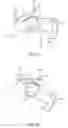
As shown in FIG. 1A, a prior-art bicycle pedal comprises a front clasp 2 and a pivotable rear clasp 3 both disposed on a pedal body 1. Further, said rear clasp 3 is provided with torsion by a torsion spring to normally keep fastened. A cleat, which is settled on the sole of a common bicycle-racing shoe, can be retained between the front clasp 2 and rear clasp 3 to fix the user's foot thereon so that a possible injury to the foot caused by accidental slips can whereby be avoided.
Since bicycle races are generally divided into road races and cross races which require different riding skills and conditions, the pedal is designed with a road-racing set and a cross-racing set on each side having various dimension and shapes for the user's option.
However, the prior-art pedal, as shown in FIG. 1B, may usually stay vertical to the ground when being installed on a bicycle because of the different weights of its two ends caused by the improper arrangement of components. It would be difficult for the user to hook the small cleat (about only 3 to 4 cm2) of a racing shoe between the clasps readily because a further manual adjustment of the pedal may be required.
SUMMARY OF THE INVENTIONThe present invention has been accomplished under the circumstances in view. The object of the present invention is to provide a structure of a pedal, which comprises a sloping first surface with a predetermined gradient and a relatively parallel second surface disposed on each side of a pedal body, a first pedal set and a second pedal set further respectively arranged on said first surface and second surface. Said two pedal sets can respectively be appointed as either a road-racing set or a cross-racing set. When the pedal is balanced on the pivot shaft of a bicycle, said first surface could be kept in a position approximately horizontal due to gravity. Thus, it would be more convenient for the user to use the first pedal set, herein namely the road-racing set, without manual modulation.
To achieve this and other objects of the present invention, the invention comprises:
-
- a multi-function pedal, which consists of a body with a first surface and a second surface. Wherein, the first surface is sloping at a predetermined gradient while the second surface is approximate parallel to the body. A first pedal set is arranged on said first surface and a second pedal set is arranged on said second surface.
FIG. 1A is a lateral plan view of a dual-purpose bicycles pedal according to the prior art.
FIG. 1B is an applied view of a dual-purpose bicycles pedal according to the prior art.
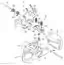
FIG. 2 is an exploded view of a Multi-Function Pedal according to the present invention.
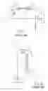
FIG. 3 is an elevation of a Multi-Function Pedal according to the present invention.
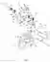
FIG. 4 is a sectional view of a Multi-Function Pedal according to the present invention.
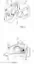
FIGS. 5A and 5B are applied views of a Multi-Function Pedal according to the present invention.
FIGS. 6A and 6B are sectional views showing actions of a hooked plate according to the present invention.
FIG. 7 is a sectional view showing actions of a seat according to the present invention.
DETAILED DESCRIPTION OF THE PREFERRED EMBODIMENTAs shown in FIGS. 2 to 4, a multi-function pedal for bicycles according to the present invention comprises:
-
- a body 10, wherein the a pivot hole 11 is disposed in the center for connecting to the crank of a bicycle; a first surface 12 and a second surface 13 wherein the former is sloping at a predetermined gradient while the latter is approximate parallel to the body 10;
- a first pedal set 20, which is arranged on the first surface 12, comprising a front clasp 21 with a retaining flange 211 at its front end; a rear clasp 22 which is connected to the front clasp 21 by a pivot pin 221; a torsion spring 222 which is disposed on the pivot pin 221 having a adjusting section 223; a tongue 212 which is extended from the rear end of the front clasp 21, having a screw 224 passing through said adjusting section 223 and then fastened with a fastening unit 225 to keep the rear clasp 22 normally staying close with said front clasp 21, wherein the user can change the pressure form said fastening unit 225 to adjusting section 223 by screwing the screw 224 to adjust the torsion of the torsion spring 222.
- a second pedal set 30 including a chamber 31 recessed in one end of the body 10 wherein the chamber 31 is opened toward the upside and rear side of the body; a one-piece fastener 32 disposed on the second surface at the other end of the body 10 opposite to the chamber 31; a hooked plate 33 with one end pivotly fixed in the chamber 31 having its the other end turned toward the pivot hole 11 and forming a retaining hook 331 which is sticking out of the second surface 13;
- a cover 332 is disposed at the end of the hooked plate 33 above the chamber 31, a seat 34 disposed on the second pedal set 30 extending toward the chamber 31, further comprising a shaft 341 which holds a spring 35; a ring groove 333 correspondingly provided inside said cover 332 to retain the other end of the spring 35 whereby when the spring 35 normally lifts the cover 332, the hooked plate 33 and its retaining hook 331 keep relatively close to the edge of the second surface 13, a adjusting hole 342 provided on the seat 34 accommodating a hexagonal nut 36 which allows a bolt 37 threading through and screwing thereon; a prominent rim 371 of the bolt 37 formed with its position between said seat 34 and the wall of the chamber 31 against the second surface 13, a retainer 372 riveted with the tail of the bolt 37 whereby the interval between the seat 34 and the wall of the chamber 31 against the second surface 13 can be adjusted by screwing the bolt 37, a through hole 311 provided on the wall of the chamber 31 correspondingly to the bolt 37 whereby said bolt 37 can be exposed on the second surface 13 of the body 10.
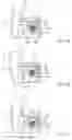
Referring to FIGS. 5A and 5B, when the pedal body 10 keeps balanced on the pivot shaft of a bicycle, the first surface 12 becomes approximately horizontal because of gravitation. Thus, it would be advantageous to the user to rapidly retain the small cleat of the road-racing shoe between the retaining flange 211 and rear clasp 22 without further manual adjustment in the gradient of said surface and body 10.
As shown in FIG. 6A, when the user is about to adopt the second pedal set 30, he needs only rotate the body 10 to make the second surface 13 upward, and put the front end of shoe cleat in the fastener 32. Then treadles the body 10 to slide the rear end of cleat along the retaining hook 331. Then the hooked plate 33 is pushed outward to bring and the cover 332 to compress the spring 35 backward to the chamber 31 (as shown in FIG. 6B). Thereafter, the resilience of the spring 35 subsequently drives the cover 332 as well as hooked plate 33 back to their former positions therefore the cleat would be tightly held by the retaining hook 331.
Further referring to FIG. 7, the prominent rim 371 presses the wall of the chamber 31 by the force of the spring 35. When the user uses a tool, for example, a screwdriver, to screw the bolt 37 at the through hole 311, the move of the bolt 37 would change the distance between the seat 34 and the wall of the chamber 31, and further cause the lifting force of the spring 35 various. Additionally, even if the user screwing the bolt 37 excessively, the retainer 372 helps to prevent the bolt 37 from coming off the body 10.
The description of the present invention has been presented for purposes of illustration and description, and is not intended to be exhaustive or limited to the invention in the form disclosed. Various modifications and enhancements may be made without departing from the spirit and scope of the invention.
Claims
What the invention claimed is:1. A multi-function pedal comprises
a body, wherein the a pivot hole is disposed in the center to connect to the crank of a bicycle;
a first surface sloping at a predetermined gradient; while
a second surface approximately parallel to the pedal body;
a first pedal set disposed on the first surface further comprising and;
a second pedal set disposed on the second surface.
2. The multi-function pedal as claimed in claim 1, wherein the first pedal set comprises a front clasp disposed on the first surface.
3. The multi-function pedal as claimed in claim 2, wherein the front clasp comprises a retaining flange at its front end.
4. The multi-function pedal as claimed in claim 3, wherein a rear clasp is arranged behind the front clasp.
5. The multi-function pedal as claimed in claim 4, wherein the front clasp and rear clasp are fixed with each other by a pivot pin.
6. The multi-function pedal as claimed in claim 5, wherein a torsion spring is disposed on the pivot pin to keep the rear clasp normally staying close with said front clasp.
7. The multi-function pedal as claimed in claim 6, wherein the torsion spring includes an adjusting section and the front clasp includes an extended tongue at the rear end. A screw is provided on the tongue and passing through the adjusting section to combine with a fastening unit
8. The multi-function pedal as claimed in claim 1, wherein, the second pedal set comprises a chamber recessed in one end of the body.
9. The multi-function pedal as claimed in claim 8, wherein a one-piece fastener is disposed on the second surface at the other end of the body opposite to the chamber.
10. The multi-function pedal as claimed in claim 9, wherein a hooked plate with its one end pivotly fixed in the chamber has the other end turned toward -the pivot hole and forming a retaining hook extended over the second surface.
11. The multi-function pedal as claimed in claim 10, wherein a cover is disposed at the end of the hooked plate above the chamber. Additionally, there is at least one spring arranged between the cover and chamber to normally lift the cover and keep the retaining hook relatively close to the edge of the second surface
12. The multi-function pedal as claimed in claim 11, wherein a seat is disposed on the second surface extending toward the chamber and comprises a shaft which holds said spring.
13. The multi-function pedal as claimed in claim 12, wherein a ring groove is correspondingly provided inside said cover to retain the other end of the spring.
14. The multi-function pedal as claimed in claim 12, wherein a bolt is provided on the seat and forms a prominent rim between the seat and the wall of the chamber against the second surface for adjusting the distance therebetween by screwing the bolt.
15. The multi-function pedal as claimed in claim 14, wherein an through hole is provided on the chamber corresponding to the bolt to allow the bolt exposed on the surface of the body.
16. The multi-function pedal as claimed in claim 14, wherein an adjusting hole is provided to inlay a hexagonal nut, which allows the bolt threading through and screwing thereon.
17. The multi-function pedal as claimed in claim 14, wherein, a retainer is disposed at the tail of the bolt.
Images & Drawings included:
Sources:
- United States Patent and Trademark Office - verify current appl. status at the USPTO↗
Recent applications in this class:
- » 20250263147 2025-08-21
PEDAL ASSEMBLY FOR HUMAN POWERED VEHICLE - » 20250178691 2025-06-05
BICYCLE PLATFORM - » 20250108881 2025-04-03
COUPLING UNIT FOR PEDAL ASSEMBLY, AND PEDAL - » 20250108880 2025-04-03
Pedal assembly for human powered vehicle - » 20250083767 2025-03-13
REVERSIBLE CONTOURED PEDALS - » 20250074541 2025-03-06
BIKE PEDAL STUD AND METHOD OF USE THEREOF - » 20240359768 2024-10-31
BICYCLE PEDAL WITH PINS WITH SKEWED TEETH - » 20240262455 2024-08-08
DECOUPLING OF A SHOE FROM A BICYCLE PEDAL - » 20240217616 2024-07-04
Clipless pedal device - » 20240109620 2024-04-04
AUTOMATIC PEDAL FOR CYCLE