Bumper assembly with fog lamp bezel
US20070182175A1
2007-08-09
11/672,273
2007-02-07
✅ Patent granted
US 7,534,021 B2
2009-05-19
-
-
H Gutman | Melissa A Black
2027-02-07
Abstract:
A bumper assembly that includes a molded bumper fascia and a molded cover/bezel mounted in an opening in the bumper. The bezel/cover is adapted to contain a fog lamp and is accurately positioned within the opening of the bumper fascia to avoid motion along the longitudinal axis of the opening, both in the forward and reverse directions, by external ribs on the cover/bezel that engage edges of the bumper to act as detents. Living hinges may be integrally molded with the bumper fascia to provide a mechanical fixation to the cover/bezel after the cover/bezel is installed in the opening and the hinges are bent from their mold positions.
Inventors:
- Umesh Naik 5 🇺🇸 Ann Arbor, MI, United States
- Randy S. Hodder 1 🇺🇸 Brighton, MI, United States
- James Castro 1 🇺🇸 Ann Arbor, MI, United States
Assignee:
- Toyota Engineering & Manufacturing North America, Inc. 75 🇺🇸 Erlanger, KY, United States
- Toyota Motor Engineering Manufacturing North America, Inc. 2,053 🇺🇸 Erlanger, KY, United States
Interested in similar patents?
Get notified when new applications in this technology area are published.
Classification:
B60R19/50 » CPC main
Wheel guards; Radiator guards, e.g. grilles ; Obstruction removers; Fittings damping bouncing force in collisions; Bumpers, i.e. impact receiving or absorbing members for protecting vehicles or fending off blows from other vehicles or objects combined with, or convertible into, other devices or objects, e.g. bumpers combined with road brushes, bumpers convertible into beds with lights or registration plates
B60R19/48 IPC
Wheel guards; Radiator guards, e.g. grilles ; Obstruction removers; Fittings damping bouncing force in collisions; Bumpers, i.e. impact receiving or absorbing members for protecting vehicles or fending off blows from other vehicles or objects combined with, or convertible into, other devices or objects, e.g. bumpers combined with road brushes, bumpers convertible into beds
B60Q1/02 IPC
Arrangement of optical signalling or lighting devices, the mounting or supporting thereof or circuits therefor the devices being primarily intended to illuminate the way ahead or to illuminate other areas of way or environments
Description
RELATED APPLICATIONThis application claims priority of U.S. Provisional Patent Application Ser. No. 60/765,935 filed Feb. 7, 2006, which is incorporated herein by reference.
FIELD OF THE INVENTIONThis invention relates to an automotive bumper fascia with a bezel that is adapted to hold a fog lamp, the bezel being accurately positioned in the bumper. The bezel serves as a cover when no fog lamp is inserted therein.
BACKGROUND OF THE INVENTIONJapanese Patent Abstract JP 06270736 discloses a bumper assembly that has a fog lamp bezel mounted therein. The arrangement of this reference uses an outer flange to prevent movement of the fog lamp bezel in a longitudinal direction and a flexible arm and detent to engage the bumper to prevent the bezel from movement in an opposite direction into the bumper.
SUMMARY OF THE INVENTIONIn the arrangement of the present invention, a bumper fascia and a bezel are coupled together by a plurality of snap detents and/or living hinge tabs to prevent movement in a longitudinal direction. Rib standoffs are provided to prevent rotation of the bezel housing within the bumper assembly that includes the bumper fascia and the bezel.
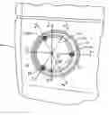
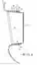
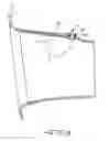
BRIEF DESCRIPTION OF THE DRAWINGSFIG. 1 is a fragmentary elevational view of a bumper assembly with a bezel that is adapted to contain a fog lamp, the bezel being mounted in the bumper assembly according to an embodiment of the present invention;
FIG. 2 is a sectional view taken on line 2-2 of FIG. 1;
FIG. 3 is a sectional view taken on line 3-3 of FIG. 1;
FIG. 4 is a sectional view taken on line 4-4 of FIG. 1;
FIG. 5 is a sectional view taken on line 5-5 of FIG. 1;
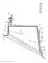
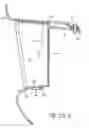
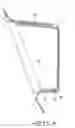
FIG. 6 is a view like FIG. 1 of an alternative embodiment of the present invention;
FIG. 7 is a view like FIG. 2 of the embodiment of the invention of FIG. 6;
FIG. 8 is a view like FIG. 3 of the embodiment of the invention of FIG. 6; and
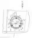
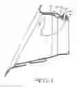
FIG. 9 is a front elevational view of the embodiment of FIGS. 1-5.
DETAILED DESCRIPTION OF THE INVENTIONReferring to FIG. 1, a bumper fascia 10 has an outer wall 12 with an opening 16 for receiving a bezel 40, the bezel 40 being adapted to have a fog lamp (not shown) inserted therein. The bezel 40 has a transversely extending wall 14 to close it off for applications where no fog lamp is to be inserted therein. The cross-sections indicated at section lines 2-2, 3-3, 4-4 and 5-5 are illustrated in FIGS. 2, 3, 4 and 5, respectively. The opening 16 is surrounded by a bumper wall 18. The bumper fascia 10 is of molded plastic construction to provide satisfactory yieldability at an acceptable cost.
The bezel 40 is contained within the bumper fascia 10 in the fore-aft or longitudinal direction as indicated in the figures by detents and, as shown in FIGS. 2 and 4, a first detent is formed by a first pair of tabs 44, 46, which extend outwardly from an outer surface of the bezel wall 42. The first tabs 44, 46 include opposing and spaced apart locating edges 48 and 50. The edges 48, 50 and 52 engage a peripheral edge of the bumper wall 18 to contain the bezel 40 in the longitudinal direction relative to the bumper fascia 10. Tuning ribs 54, 56 are formed in the bumper fascia 18 and the bezel wall 42, respectively, for locating in a direction substantially perpendicular to the longitudinal direction. The ribs 54 and 56, which are inserted in slots 90 in the fascia wall 18 can be lengthened or shortened to accommodate assembly tolerances.
As shown in FIGS. 1 and 4, a second detent formed by a second tab 64 that extends outwardly from the outer surface of the bezel wall 42. The second tab 64 includes a locating edge 70. The edge 70 of the second tab 64 engages the peripheral edge of the fascia wall 18, and a second locating edge 72, respectively, formed in the bumper wall 18 to constrain the bezel 40 in the longitudinal direction relative to the bumper fascia 10.
As shown in FIGS. 3 and 5, a third detent is formed by a third pair of tabs 46, 86, which extend outwardly from the outer surface of the bezel wall 42. The third tabs 46, 86 include opposite and spaced apart locating edges 50, 90. As shown in FIG. 1, the third tabs 46, 86 are also spaced apart in a circumferential sense. Edges 50, 90 of the third tabs 46, 86, respectively, engage the peripheral edge of the fascia wall 18.
In summary, outward movement of the bezel 40 along its longitudinal central axis is constrained at 3 locations, by the tab 44 in its engagement with the fascia wall 18, by the tab 64 in its engagement with the fascia wall 18, and by the engagement of the tab 86 with fascia wall 18. Likewise, inward movement of the bezel 40 along its longitudinal central axis is constrained at 3 locations, by the tab 46 in its engagement. with the fascia wall 18, by the tab 50 in its engagement with the fascia wall 18 and by the tab 86 in its engagement with the fascia wall 18.
As shown in FIGS. 6-9, at least an end wall 120 of the embodiment depicted herein is coupled to the bumper fascia 10 by a living hinge 122. The end wall 120 and living hinge 122 are integrally formed during molding of the bumper fascia 10. The mold and installed positions are indicated in these figures, In assembly, the end wall 120 is bent about the hinge 122 from the mold position to the installed position. A bolt 124 or other threaded fastener is assembled through corresponding holes 126, 128 formed in the end wall 120 and a bezel wall 142, respectively, for securing a bezel/cover 140 to the bumper fascia 10. This construction provides a mechanical fixation to the bezel/cover. The feature of the embodiment of FIGS. 6-9 may be used in conjunction with its features of the embodiment of FIGS. 1-5 or independently thereof in which case the bumper fascia 10 will be provided with a living hinge 22 that is secured to an extension 20 of the bezel/cover 40 by a bolt 24,
Although the best mode contemplated by the inventors for carrying out the present invention as of the filing date hereof has been shown and described herein, it will be apparent to those skilled in the art that suitable modifications, variations and equivalents may be made without departing from the scope of the invention, such scope being limited solely by the terms of the following claims.
Claims
1. An assembly comprising, in combination:
a molded bumper fascia having a wall defining an opening therein;
a bezel/cover positioned in the opening;
a spaced pair of first tabs extending from said bezel/cover, each of said first tabs having a locating edge; and
each locating edge of each of said first pair of tabs engaging said wall of said bumper fascia to restrain the motion of said bezel/cover relative to said bumper in a longitudinal direction of the opening of said bumper.
2. An assembly according to claim 1 and further comprising:
at least one of said wall of said bumper fascia and said bezel/cover being provided with at least one radial turning rib, said at least one turning rib in said wall of said one of said bumper and said bezel/cover engaging the other of said bumper and said bezel/cover to restrain turning movement of said bezel/cover in said opening of said bumper.
3. An assembly according to claim 2 and further comprising:
at least a circumferentially spaced pair of third tabs, each of said third tabs extending outwardly from said bezel and engaging the wall of said bumper fascia to prevent reverse relative motion of said bezel/cover in a longitudinal direction relative to said bumper.
4. An assembly according to claim 2 wherein:
said bumper fascia has at least one living hinge molded integrally with said bumper fascia, said at least one living hinge being bent from a mold position to engage said bezel/cover after the bezel/cover is installed in the opening of said bumper/fascia.
5. An assembly according to claim 4 and further comprising:
at least one threaded fastener securing said bezel/cover to said bumper fascia, said at least one threaded fastener fastened through aligned holes in said bumper fascia and said bezel/cover.
6. An assembly comprising, in combination:
a molded bumper fascia having a wall defining an opening therein;
a bezel adapted to contain a lamp therein, said bezel being positioned in said opening of said bumper fascia; and
said bumper fascia having at least one living hinge molded integrally with said bumper fascia, said at least one living hinge being bent from a mold position to engage a bezel/cover when said bezel/cover is installed in the opening of said bumper fascia.
7. An assembly according to claim 6 and further comprising:
at least one threaded fastener securing said bezel/cover to said bumper fascia, said at least one threaded fastener fastened through aligned holes in said bumper fascia and said bezel/cover.
Images & Drawings included:
Sources:
- United States Patent and Trademark Office - verify current appl. status at the USPTO↗
Recent applications in this class:
- » 20250276662 2025-09-04
Front Bumper Assembly Support in Vehicles - » 20240383426 2024-11-21
VEHICLE BUMPER WITH SELECTIVELY DEPLOYABLE INTEGRATED LIGHT BAR - » 20240375600 2024-11-14
BUMPER WITH SELECTIVELY ATTACHABLE LIGHT BARS - » 20240051482 2024-02-15
MODULAR PUSH BUMPER - » 20230382336 2023-11-30
VEHICLE BUMPER WITH SELECTIVELY DEPLOYABLE INTEGRATED LIGHT BAR - » 20230084793 2023-03-16
VEHICLE BUMPER WITH SELECTIVELY DEPLOYABLE INTEGRATED LIGHT BAR - » 20230069186 2023-03-02
Vehicle bumper assembly - » 20220402450 2022-12-22
Bumper with selectively attachable light bars - » 20220250569 2022-08-11
Skid plate assembly - » 20220203914 2022-06-30
LIGHTED VEHICLE STEP PAD AND VEHICLE LIGHT SOURCE
Recent applications for this Assignee:
- » 20240013587 2024-01-11
Partial sensor data sharing for connected vehicles - » 20230219580 2023-07-13
Driver and vehicle monitoring feedback system for an autonomous vehicle - » 20220215698 2022-07-07
Partial sensor data sharing for connected vehicles - » 20220126850 2022-04-28
SYSTEM AND METHOD FOR DETERMINING DRIVER PREFERENCES FOR AUTONOMOUS VEHICLES - » 20210257138 2021-08-19
Inductor with variable permeability core - » 20210182739 2021-06-17
ENSEMBLE LEARNING MODEL TO IDENTIFY CONDITIONS OF ELECTRONIC DEVICES - » 20210161029 2021-05-27
Systems and methods for additive manufacturing of wick structure for vapor chamber - » 20210127242 2021-04-29
Vehicular communications based on internet communication identifiers associated with codes of vehicles - » 20210124009 2021-04-29
Triangulation and calibration of electronic control units - » 20210118243 2021-04-22
Vehicular communications through identifiers and online systems