Safety circuit technique for high current shut-down
US20070183109A1
2007-08-09
10/778,894
2004-02-13
Abstract:
A safety circuit technique for high current shut-down monitors a battery pack and, when certain conditions exist, performs a series of safety measures, or a safety checklist and actions, to safely and quickly turn the battery cell off. In a preferred embodiment, diodes are used to prevent the IC drive current from being exceeded.
Inventors:
- Lance Chandler 3 🇺🇸 Gig Harbor, WA, United States
- David Sorlien 2 🇺🇸 Escondido, CA, United States
- Don Buckingham 1 🇺🇸 Greenville, OH, United States
Assignee:
- Poweready, Inc. 2 🇺🇸 Milpitas, CA, United States
Interested in similar patents?
Get notified when new applications in this technology area are published.
Classification:
H02H7/18 » CPC main
Emergency protective circuit arrangements specially adapted for specific types of electric machines or apparatus or for sectionalised protection of cable or line systems, and effecting automatic switching in the event of an undesired change from normal working conditions for batteries; for accumulators
H02H3/08 IPC
Emergency protective circuit arrangements for automatic disconnection directly responsive to an undesired change from normal electric working condition with or without subsequent reconnection ; integrated protection responsive to excess current
Description
RELATED APPLICATIONThis application claims the benefit of priority to U.S. Provisional Patent Application No. 60/447,478 filed Feb. 13, 2003, and currently co-pending.
FIELD OF THE INVENTIONThe present invention relates generally to a safety system used in computer shutdown system. More specifically to the method used in circuits for the safety of computer shut down systems.
BACKGROUND OF THE INVENTIONIn a device containing a battery system where an error occurs, such as an over-current being supplied from the battery pack, it is imperative to remove the cell from the circuit as quickly as possible. Despite the existence of fast switching transistors, current safety circuits inherently contain a delay in the disconnect of the affected cell. Unfortunately, any delay, even a very brief delay, can damage or destroy the battery cell.
DESCRIPTION OF THE PREFERRED EMBODIMENTThe Safety Circuit Technique for High Current Shut-Down of the present invention monitors a battery pack and, when certain conditions exist, performs a series of safety measures, or a safety checklist and actions, to safely and quickly turn the battery cell off. In a preferred embodiment, diodes are used to prevent the IC drive current from being exceeded.
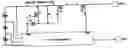
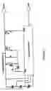
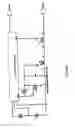
Referring to FIG. 1, a preferred embodiment of the safety circuit of the present invention is shown. This circuit is for a high-side implementation of the safety circuit. FIG. 2 depicts a preferred embodiment of the safety circuit of the present invention is shown. This circuit is for a low-side implementation of the safety circuit.
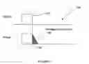
Referring to FIG. 3, a diagram showing the discharge signal on the safety circuits of FIGS. 1 and 2, and the resulting output current (power) is generally designated 100. Control signal 102 is in the “on” state, and at results in a corresponding non-zero power output 104. However, when an error occurs, the control signal 102 goes to the “off” state. This “off” state turns the switching transistors within the safety circuit to a non-conductive state, whereby the output power goes to zero. However, since there is an inherent level of capacitance within the switching transistors (preferably Field Effect Transistors (“FET”)), at the trailing edge of the power output exists a short-circuit current area 106. The short-circuit current area 106 is where the damage occurs to the safety circuit by, among other items, exceeds the power rating of the FET. To eliminate the formation of the short circuit current 106, a diode Dl is inserted into the circuit to prevent the IC drive current from being exceeded, as shown in FIGS. 1 and 2.
Claims
1. A safety circuit technique for high current shut-down, includes the steps of:
monitoring a battery pack;
performing a series of safety measures; and
turning off said battery cell.
Images & Drawings included:
Sources:
- United States Patent and Trademark Office - verify current appl. status at the USPTO↗
Recent applications in this class:
- » 20250174982 2025-05-29
Temperature Triggered Alert Apparatus - » 20250174981 2025-05-29
DRIVER APPARATUS AND CORRESPONDING METHOD - » 20250174980 2025-05-29
ISOLATION DIAGNOSTICS OF ELECTRICAL ENERGY STORAGE PACKS WHILE UNDER LOAD - » 20250158388 2025-05-15
BATTERY PACK CONTROL APPARATUS AND METHOD FOR FIXING FAILURE OF RELAY - » 20250141212 2025-05-01
PROTECTION CIRCUIT MODULE AND BATTERY PACK INCLUDING THE SAME - » 20250132557 2025-04-24
POWER SUPPLY CIRCUIT, BATTERY MONITORING CIRCUIT, AND ENERGY STORAGE DEVICE - » 20250118957 2025-04-10
HIGH-PRECISION CURRENT DETECTION METHOD AND CHIP MODULE THEREFOR - » 20250038521 2025-01-30
Electronic control unit for vehicle with integrated cut-off - » 20250007277 2025-01-02
POWER BATTERY AND CONTROL SYSTEM AND CONTROL METHOD THEREFOR - » 20240364100 2024-10-31
OVERCURRENT PROTECTION BASED ON SLOPE DETECTION
Recent applications for this Assignee:
- » 20070033246 2007-02-08
Thin metal film uninterruptable power supply system