Stress and strain analysis method and its equipment
US20070186674A1
2007-08-16
11/655,219
2007-01-19
✅ Patent granted
US 7,509,872 B2
2009-03-31
-
-
Harshad Patel | Freddie Kirkland, III
2027-06-17
Abstract:
Provided are a stress analysis method and stress analysis equipment that enable a detailed stress measurement, by using both a photoelasticity measurement method and a stress measurement (mechanoluminescence measurement) which utilizes a mechanoluminescent substance to measure a stress state of an object. Physical quantities that are measurable include individual principal stress component and a principal stress direction. The photoelasticity measurement method alone cannot measure individual principal stress component values.
Inventors:
- Chao-Nan XU 10 🇯🇵 Saga, Japan
- Koji HYODO 22 🇯🇵 Ibaraki, Japan
- Takashi Yamane 2 🇯🇵 Ibaraki, Japan
- Motoyuki Akamatsu 3 🇯🇵 Ibaraki, Japan
- Yoshiyuki Yokogawa 2 🇯🇵 Aichi, Japan
- Tetsuya Kameyama 3 🇯🇵 Aichi, Japan
Assignee:
- National Institute of Advanced Industrial Science and Technology 1,844 🇯🇵 Tokyo, Japan
- NATIONAL INSTITUTE OF ADVANCED INDUSTRIALS SCIENCE AND TECHNOLOGY 1 🇯🇵 Tokyo, Japan
Interested in similar patents?
Get notified when new applications in this technology area are published.
Classification:
G01N3/068 » CPC main
Investigating strength properties of solid materials by application of mechanical stress; Details; Special adaptations of indicating or recording means with optical indicating or recording means
G01N3/14 » CPC further
Investigating strength properties of solid materials by application of mechanical stress by applying steady tensile or compressive forces generated by dead weight, e.g. pendulum; generated by springs tension
G01N2203/0033 » CPC further
Investigating strength properties of solid materials by application of mechanical stress; Generation of the force using mechanical means Weight
G01N3/08 IPC
Investigating strength properties of solid materials by application of mechanical stress by applying steady tensile or compressive forces
Description
BACKGROUND OF THE INVENTION1. Field of the Invention
The present invention relates to a stress and strain analysis method and stress and strain analysis equipment that enable a more detailed determination of a stress and strain state of an object.
2. Description of the Related Art
Safety from a dynamic viewpoint in various products such as airplanes, trucks, piping in power plants, bridges, and orthopedic and dental implants is a basic and indispensable element for realizing a worry-free and safe society. Also, for realization and evaluation of safety of the products from the dynamic viewpoint, a stress and strain measurement technology plays an important role.
Conventionally, a strain gauge method has been used for measurement of a stress distribution. In the strain gauge method, many strain gauges are stuck to a surface of a measurement target object, and a stress and strain distribution is determined based on an output signal from each strain gauge at the time of application of a load. With this method, quantitative measurement is possible but in the case of a wide measurement area or a narrow measurement area, a thorough measurement is impossible due to a limit on the number of gauges that can be stuck in the area.
Therefore, a photoelasticity measurement method has also been used. In the photoelasticity measurement method, a stress distribution is measured by utilizing a temporary photobirefringent property that occurs in accordance with the amount of a stress at the time of application of a load to a sample. There are various photoelasticity measurement methods such as a method in which measurement is conducted using a transparent model with a similar shape to a real sample, and a method in which measurement is conducted by forming a photoelastic coating for a surface of a real sample. Each of those methods has a feature that it is possible to measure a stress as an image.
Meanwhile, an applicant of the present invention has studied an inorganic material that emits light in response to mechanical energy and have succeeded in manufacturing a material, including a base material that is a piezoelectric body having, in particular, a wurtzite structure and an inorganic substance having a luminescence center, as described in Japan Patent Publication No. 11-120801 A (Japan Patent No. 3-265356 B). The applicant of the present invention has found that it is possible to dramatically improve the light intensity emitted from an obtained thin film by adding an inorganic substance to the base material described above and have filed a patent application. Thereafter, as a result of a further study, the applicant of the present invention has found various inorganic substances that emit light in response to such forces (mechanoluminescence material), as disclosed in U.S. Pat. No. 7,060,371, and are also conducting a study for using such substances in various fields. For instance, as disclosed in JP 2003-137622 A, the applicant of the present invention propose a technique of detecting an abnormal stress that is a harbinger of destruction of concrete by mixing a mechanoluminescence material into the concrete.
As described above [04], in the photoelasticity measurement method, a stress distribution of an object is measured as an image. For instance, in the photoelasticity measurement method by a general plane polariscope, the light intensity I observed after passing an analyzer is expressed as follows:
I=I0 sin2 2Ψ sin2(ρ/2) (1)
where
-
- I0: incident light intensity,
- Ψ: principal stress direction of a sample, and
- ρ: relative phase difference.
Here, the relative phase difference ρ and a fringe order N are expressed as follows:
ρ=2παt(σ1−σ2), and (2)
N=αt(σ1−σ2) (3)
where
-
- α: photoelasticity sensitivity, and
- t: thickness of the sample.
The photoelasticity sensitivity α is expressed by the following equation:
α=2πC/λ (4)
where
-
- C: Brewster's constant, and
- λ: light wavelength.
As expressed by Equations (1) to (4), with this technique, two information items are obtained. That is, at the time when Ψ is equal to 0 or π/2, a principal stress direction can be found from a black fringe (isoclinic line), in which a principal stress axis coincides with an optical axis at a point where I is equal to 0, and a principal stress difference can be found from a black fringe (isochromatic line) that becomes a positive integer (such as N=0, 1, 2 . . . ).
This technique, however, has a fundamental limitation in that it is impossible to obtain individual stress component values σ1 and σ2.
SUMMARY OF THE INVENTIONTherefore, an object of the present invention is to provide a stress analysis method and stress analysis equipment, which allow a more detailed stress measurement than can be provided by a photoelasticity measurement method alone by using both the photoelasticity measurement method and a stress measurement, which utilizes a mechanoluminescence material, to measure a state of a stress of an object.
In order to solve the above-mentioned problem [09], the applicants of the present invention have found a technique of applying a substance that emits light in response to mechanical energy, which has been developed by the applicant of the prsent invention in the past as described above [05], for stress measurement. More specifically, the present invention provides a technique that uses a photoelasticity stress measurement method and a method (defined as the “mechanoluminescence measurement method”) in which a mechanoluminescence substance is applied to an object through application, mixing, or the like, light emitted in response to a load is captured with light detecting equipment (such as a camera), and a stress distribution or the like is measured. That is, the stress analysis method according to the present invention includes: measuring a state of a stress which acts on a measurement target object by measuring photobirefringence of a substance caused by the stress (photoelasticity measurement); measuring the state of the stress which acts on the measurement target object by measuring light emitted from a substance in response to the stress (mechanoluminescence measurement); and obtaining dynamic information including a stress distribution by arithmetically processing data obtained as a result of the photoelasticity measurement and data obtained as a result of the mechanoluminescence measurement.
Further, the dynamic information may be normal stress component distribution information.
The dynamic information may be shearing stress distribution information.
The dynamic information may be stress direction information.
Further, according to another aspect of the present invention, a stress analysis equipment is provided, including: a photoelasticity measurement means for measuring a state of a stress which acts on a measurement target object by measuring photobirefringence of a substance caused by the stress; a mechanoluminescence measurement means for measuring the state of the stress which acts on the measurement target object by measuring light emitted from a substance in response to the stress; and an arithmetic processing means for obtaining dynamic information including a stress distribution, by arithmetically processing data obtained by the photoelasticity measurement means and data obtained by the mechanoluminescence measurement means.
Further, the dynamic information may be normal stress component distribution information.
The dynamic information may be shearing stress distribution information.
The dynamic information may be stress direction information.
In measuring a stress distribution of an object, it becomes possible to measure a more detailed stress state than can be accomplished using the photoelasticity measurement method alone. For instance, when using the photoelasticity measurement method alone it is impossible to obtain principal stress component values.
BRIEF DESCRIPTION OF THE DRAWINGSIn the accompanying drawings:
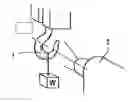
FIGS. 1A and 1B are explanatory diagrams according to an exemplary embodiment of the present invention, in which FIG. 1A shows a state where a stress distribution at the time when a load W is applied to a hook as a test piece is measured, and FIG. 1B is a functional block diagram according to an exemplary embodiment of the present invention; and
FIG. 2 is an explanatory diagram showing a state where predetermined stress distribution information is obtained by arithmetically processing mechanoluminescence photographed image data and photoelasticity stress photographed image data in an exemplary embodiment of the present invention.
DETAILED DESCRIPTION OF THE EXEMPLARY EMBODIMENTSThe exemplary embodiments of the present invention are realized by performing both photoelasticity stress measurement and mechanoluminescence measurement to measure a stress distribution of an object. By performing arithmetic processing or the like using data obtained as a result of the photoelasticity stress measurement and data obtained as a result of the mechanoluminescence measurement, it becomes possible to obtain stress information that cannot be obtained through only one of the measurements.
FIG. 1A shows a case where a load W is applied to a hook 1 as a test target piece. That is, in an exemplary embodiment of the present invention, the hook 1 to which the load is applied is photographed with a camera 2, as shown in FIG 1A. The camera 2 that has conventionally been used in photoelasticity measurement is used to photograph birefringence caused by a stress and a strain that act on the hook 1 (photoelasticity optical system is omitted from the figure). In addition, a substance that emits light in response to a stress is applied to the hook 1 and a state where the substance emits light on receiving the stress is photographed with a camera. Here, the photoelasticity measurement and the mechanoluminescence measurement can be obtained from different cameras or the same camera.
With reference to image data obtained as a result of the photographing as described above, a photoelasticity stress distribution is measured at a photoelasticity stress measurement portion 4 shown in FIG. 1B and a mechanoluminescence distribution is measured at a mechanoluminescence measurement portion 3. Those measurement data items are arithmetically processed at an arithmetic processing portion 5. A result of the arithmetic processing is outputted from a data output portion 6 to an image output portion 7 as, for instance, an image and is displayed on a monitor or the like.
In FIG. 2, an exemplary analysis for the case described above, where the load W is applied to the hook 1, is schematically shown. Mechanoluminescence image data obtained in operation (a) and photoelasticity image data obtained in operation (b) are both arithmetically processed in operation (c), thereby making it possible to obtain stress information, such as individual principal stress component values (σ1 and σ2), which cannot be obtained with only one of the mechanoluminescence image data and the photoelasticity image data. Hereinafter, an example of basic theory of the exemplary embodiments of the present invention will be described.
It is made possible to acquire physical quantities which cannot be fundamentally measured with only one of the photoelasticity stress measurement method and the mechanoluminescence measurement method, in other words, principal stress component values (σ1 and σ2) by using the two techniques in combination.
A surface stress of a sample (isotropic elastic body) is examined in a plane stress state. With respect to the principal stresses σ1 and σ2, it is possible to express strains ε1 and ε2 as follows:
ε1=(1/E)×(σ1−νσ2) (5)
ε2=(1/E)×(σ2−νσ1) (6)
where E indicates a modulus of longitudinal elasticity and ν indicates Poisson's ratio.
Also, elastic energy u is as follows:
u=(1/2)×(σ1ε1+σ2ε2) (7)
Therefore, when Equations (5) and (6) are substituted into Equation (7), the following equations are obtained:
u
=
(
1
/
2
E
)
×
(
σ
1
2
+
σ
2
2
)
-
v
/
E
×
σ
1
σ
2
=
(
1
/
2
E
)
×
(
σ
1
2
+
σ
2
2
-
2
v
σ
1
σ
2
)
=
(
1
/
2
E
)
×
(
(
σ
1
+
σ
2
)
2
-
2
σ
1
σ
2
-
2
v
σ
1
σ
2
)
(
8
)
(
9
)
(
10
)
Also, it is possible to measure a principal stress difference with the photoelasticity measurement method, so when a value that can be obtained is referred to as “A” and the following Equations (11) and (12) are substituted into Equation (6):
σ1−σ2=A (11)
σ2=−A+σ1 (12)
Equation (13) given below is obtained:
u=[((1−ν)/E)×σ12]−[(A(1−ν)/E)×σ1]+(A2/2E) (13)
When this equation is modified, a quadratic equation concerning σ1 is obtained as follows:
[((1+ν)/E)×σ12]−[(A(1+ν)/E)×σ1]+((A2/2E)−u)=0 (14)
The elastic energy u is information that can be obtained with the mechanoluminescence method, so all of the following three coefficients of this equation become known values:
(1−ν)/E=B (15)
−A(1−ν)/E=C (16)
(A2/2E)−u=D (17)
Accordingly, when Equation (10) that is a quadratic equation concerning σ1 is solved, it is possible to obtain the following solutions:
σ1=(−C±(C2−4BD)1/2)/(2B) (18)
σ2=A−σ1 (19)
It is possible to uniquely determine plus/minus signs in Equation (14) from absolute values or calibration. Note that this result can also be expressed as follows:
(σ1,σ2)=(−C±(C2−4BD)1/2)/(2B) (20)
It is possible to carry out the process described above based on a two-dimensional image obtained with the photoelasticity measurement method and the mechanoluminescence method, and to present a result of the process in the form of an image. Also, when a principal stress direction that can be found with the photoelasticity measurement method and the result of the process are combined with each other, complete stress information, which includes individual principal stress components and the principal stress direction, becomes clear.
The exemplary embodiments of the present invention are usable in various fields in which it is preferable to measure a stress distribution. For instance, when a mechanoluminescent substance is applied to a product or a model created with three-dimensional modeling equipment or the like through mixing, application, or the like and the photoelasticity measurement and the mechanoluminescence measurement are performed, it becomes possible to perform a detailed surface stress analysis, confirmation of a stress concentrated area, or the like for the sake of, for instance, prevention of breakage or a fatigue failure.
Also, for instance, when a mechanoluminescent substance is applied to a component, a model, or the like created by performing cutting machining or the like through application or the like and the photoelasticity measurement and the mechanoluminescence measurement are performed, a detailed surface stress analysis becomes possible. Consequently, it becomes possible to perform confirmation of a stress concentrated area for the sake of, for instance, prevention of breakage or a fatigue failure.
Further, accuracy of a simulation based on a finite element method or the like depends on a degree of similarity between boundary conditions set for the simulation and those of an actual object. It is possible to improve the accuracy of the simulation by confirming stress components of the actual object and a model through the photoelasticity measurement and mechanoluminescent measurement and optimizing the boundary conditions or the like of the simulation.
Still further, for instance, when the measurement is performed for a simulation bone fitted with an orthopedic or dental implant, it becomes possible to obtain a detailed surface stress distribution of the implant, which enables a more detailed dynamic compatibility evaluation of the implant.
Also, for instance, when the photoelasticity measurement and the mechanoluminescence measurement are performed using a magnifying optical system such as a microscope, a high-precision stress analysis of a minute area (such as micromachine) which cannot be measured with a conventional technique becomes possible.
Also, when an optically transparent material is used in both of the techniques, it becomes possible to measure not only a surface stress but also an internal stress.
Needless to say, it is possible to supplement the method of the exemplary embodiments with a stress measurement method, such as a strain gage method, for the sake of calibration or the like.
The exemplary embodiments of present invention enable detailed stress distribution measurement that cannot be provided by the photoelasticity method alone and, therefore, are usable in various industrial fields in which stress measurement is required.
Claims
What is claimed is:1. A stress analysis method, comprising:
measuring a state of a stress which acts on a measurement target object by measuring photobirefringence of a first substance caused by the stress;
measuring the state of the stress which acts on the measurement target object by measuring light emitted from a second substance in response to the stress; and
obtaining dynamic information including a stress distribution by arithmetically processing data obtained as a result of the photoelasticity measurement and data obtained as a result of the mechanoluminescence measurement.
2. A stress analysis method according to claim 1, wherein the dynamic information comprises normal stress component distribution information.
3. A stress analysis method according to claim 1, wherein the dynamic information comprises shearing stress distribution information.
4. A stress analysis method according to claim 1, wherein the dynamic information comprises stress direction information.
5. A stress analysis equipment, comprising:
a photoelasticity measurement means for measuring a state of a stress which acts on a measurement target object by measuring photobirefringence of a first substance caused by the stress;
a mechanoluminescence measurement means for measuring the state of the stress which acts on the measurement target object by measuring light emitted from a second substance in response to the stress; and
an arithmetic processing means for obtaining dynamic information including a stress distribution by arithmetically processing data obtained by the photoelasticity measurement means and data obtained by the mechanoluminescence measurement means.
6. A stress analysis equipment according to claim 5, wherein the dynamic information comprises normal stress component distribution information.
7. A stress analysis equipment according to claim 5, wherein the dynamic information comprises shearing stress distribution information.
8. A stress analysis equipment according to claim 5, wherein the dynamic information comprises stress direction information.
Images & Drawings included:


Sources:
- United States Patent and Trademark Office - verify current appl. status at the USPTO↗
Recent applications in this class:
- » 20250258071 2025-08-14
STRAIN MEASUREMENT APPARATUS AND METHOD FOR MEASURING MECHANICAL STRAIN - » 20250208013 2025-06-26
Apparatus for Testing the Degree of Peeling of Electrode Active Material - » 20250067646 2025-02-27
APPARATUS AND METHOD FOR CAPTURING CHANGES IN POSITION OF AT LEAST ONE COMPONENT MOUNTED IN AN ASSEMBLY - » 20250067645 2025-02-27
NON-CONTACT, AUTOGENOUS MATERIAL ASSESSMENT - » 20250044200 2025-02-06
SEALING QUALITY TESTING APPARATUS FOR DETERMINING THE QUALITY OF A SEALING BAND, PACKAGING PLANT HAVING A SEALING QUALITY TESTING APPARATUS, METHOD FOR DETERMINING THE QUALITY OF A SEALING BAND AND METHOD FOR PRODUCING COMPOSITE PACKAGES - » 20240402061 2024-12-05
UNIAXIAL-BIAXIAL-TRIAXIAL APPARATUS AND METHOD FOR IN-AIR AND IN-SOIL TESTING OF GEOSYNTHETIC MATERIALS - » 20240328913 2024-10-03
CONFIGURABLE MATERIALS TESTING - » 20240288348 2024-08-29
SET CEMENT MECHANICAL PROPERTIES PARAMETER MEASUREMENT METHOD AND APPARATUS BASED ON IMAGE RECOGNITION TECHNOLOGY - » 20240255397 2024-08-01
TEST SHEET AND MEASUREMENT METHOD - » 20240230490 2024-07-11
METHOD AND MEASURING DEVICE FOR DETECTING MEASUREMENT SIGNALS
Recent applications for this Assignee:
- » 20250267902 2025-08-21
SUPERJUNCTION SILICON CARBIDE SEMICONDUCTOR DEVICE HAVING PARALLEL PN COLUMN STRUCTURE WITH CRYSTAL DEFECTS - » 20250238002 2025-07-24
CONTROL SYSTEM, CONTROL METHOD, AND RECORDING MEDIUM - » 20250237797 2025-07-24
WIRE GRID POLARIZING ELEMENT AND METHOD FOR PRODUCING SAME - » 20250233150 2025-07-17
GRAPHITE PARTICLES - » 20250216772 2025-07-03
PELLICLE FILM FOR PHOTOLITHOGRAPHY, PELLICLE, PHOTOLITHOGRAPHY MASK, PHOTOLITHOGRAPHY SYSTEM, AND METHOD OF PRODUCING PELLICLE FILM FOR PHOTOLITHOGRAPHY - » 20250215424 2025-07-03
SINGLE-STRAND FORM POLYNUCLEOTIDE AND USE THEREOF IN GENOME EDITING - » 20250210235 2025-06-26
SAMARIUM-IRON-NITROGEN BASED MAGNET POWDER AND SAMARIUM-IRON-NITROGEN BASED MAGNET - » 20250205731 2025-06-26
PEROVSKITE CRYSTAL DEPOSITION METHOD AND DEPOSITION APPARATUS - » 20250201457 2025-06-19
Sm-Fe-N-BASED MAGNETIC MATERIAL AND PRODUCTION METHOD THEREOF - » 20250182853 2025-06-05
METHOD FOR PRODUCING LIBRARY BY MACHINE LEARNING