Hybrid power train and operating method therefor
US20070187160A1
2007-08-16
11/579,055
2005-04-27
✅ Patent granted
US 7,950,480 B2
2011-05-31
WO; PCT/FR2005/050283; 20050427
WO; WO2005/110795; 20051124
J. Allen Shriver, II | Jacob Meyer
2027-11-02
Abstract:
A hybrid motor vehicle power train (10) operating in thermal mode or electric mode and including a thermal engine (20) coupled to a gearbox (100) via a clutch (113) and an electrical machine (200), characterised in that the electrical machine is continuously connected to the input shaft (130) of the gearbox (100).
Assignee:
- RENAULT s.a.s. 1,301 🇫🇷 Boulogne-Billancourt, France
Interested in similar patents?
Get notified when new applications in this technology area are published.
Classification:
B60K6/405 » CPC main
Arrangement or mounting of plural diverse prime-movers for mutual or common propulsion, e.g. hybrid propulsion systems comprising electric motors and internal combustion engines the prime-movers consisting of electric motors and internal combustion engines, e.g. HEVs characterised by apparatus, components or means specially adapted for HEVs characterised by the assembly or relative disposition of components Housings
B60K6/36 » CPC further
Arrangement or mounting of plural diverse prime-movers for mutual or common propulsion, e.g. hybrid propulsion systems comprising electric motors and internal combustion engines the prime-movers consisting of electric motors and internal combustion engines, e.g. HEVs characterised by apparatus, components or means specially adapted for HEVs characterised by the transmission gearings
B60K6/547 » CPC further
Arrangement or mounting of plural diverse prime-movers for mutual or common propulsion, e.g. hybrid propulsion systems comprising electric motors and internal combustion engines the prime-movers consisting of electric motors and internal combustion engines, e.g. HEVs; Architecture of the driveline characterised by arrangement or kind of transmission units; Transmission for changing ratio the transmission being a stepped gearing
F16H3/089 » CPC further
Toothed gearings for conveying rotary motion with variable gear ratio or for reversing rotary motion without gears having orbital motion exclusively or essentially with continuously meshing gears, that can be disengaged from their shafts characterised by the disposition of the gears all of the meshing gears being supported by a pair of parallel shafts, one being the input shaft and the other the output shaft, there being no countershaft involved
Y02T10/62 » CPC further
Road transport of goods or passengers; Other road transportation technologies with climate change mitigation effect Hybrid vehicles
Y02T10/62 » CPC further
Road transport of goods or passengers; Other road transportation technologies with climate change mitigation effect Hybrid vehicles
B60K6/00 IPC
Arrangement or mounting of plural diverse prime-movers for mutual or common propulsion, e.g. hybrid propulsion systems comprising electric motors and internal combustion engines
B60K6/48 » CPC further
Arrangement or mounting of plural diverse prime-movers for mutual or common propulsion, e.g. hybrid propulsion systems comprising electric motors and internal combustion engines the prime-movers consisting of electric motors and internal combustion engines, e.g. HEVs characterised by the architecture of the hybrid electric vehicle Parallel type
Description
The invention relates to a motor vehicle power train with a hybrid, electric and combustion, drive comprising two drive units, one an electric motor and the other a combustion engine, operating mainly in combustion mode.
More specifically, the subject of the invention is a hybrid motor vehicle power train operating in combustion mode or in electric mode, of the type comprising a combustion engine coupled to a gearbox via a clutch, and an electric machine.
Various ways of arranging an electric machine in a hybrid power train are known.
In one known arrangement, illustrated in particular by the publications FR 2 822 109 and FR 2 837 429, the stator of the electric machine can be fixed to the gearbox housing, itself secured to the housing of the combustion engine, while the rotor is connected to the planet pinion of a planetary gear train.
In another known arrangement, in particular that known from publication EP 1 232 890, the electric machine can be placed in a lateral position of the gearbox, the electric machine then being permanently connected to the secondary shaft by a chain and a pair of wheels added to the end of the primary and secondary shafts.
The disadvantage with these known arrangements is the additional axial bulk of the power train, which cannot be made compatible with transverse installations without difficulty.
To overcome this disadvantage, the invention proposes that the electric machine is permanently connected to the primary shaft of the gearbox, preferably by a chain, and offset laterally with respect to the combustion engine.
It also proposes that:
-
- with the vehicle stopped, the combustion engine is started by putting the gearbox in the neutral position and by closing the clutch for coupling the crankshaft and the input shaft of the gearbox, that
- with the vehicle running in electric mode, the combustion engine is started by closing the clutch for coupling the crankshaft and the input shaft of the gearbox, that
- the power train has a main combustion operating mode, the electric machine then performing the functions of alternator, of motor for applying extra torque at the low speeds of the combustion engine, and of an electric brake when slowing down, that
- the power train has an electric operating mode, the clutch for coupling the crankshaft and the input shaft of the gearbox then being open, and the electric machine then being able to propel the vehicle forward in the first and second gear ratios of the gearbox and in reverse by reversing the direction of rotation, in the second gear ratio, and that
- the gearbox is robotized.
Other features and advantages of the invention will become clearly apparent on reading the detailed description given below of an embodiment which does not limit the invention, with reference to the appended drawings, in which:
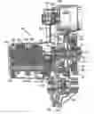
FIG. 1 is an axial overview of the proposed power train, without the combustion engine, and
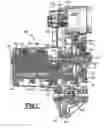
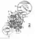
FIG. 2 is a partial cross section thereof.
FIG. 1 shows the whole of the power train 10. The combustion engine 20 is represented by way of the nose of the crankshaft, to which is fastened a damping flywheel 30 composed of an actual flywheel 31, of a vibration damper 32 and of a damping device 33, corresponding, for example, to publication FR 2 833 329.
The combustion engine is coupled via splines 32a of the damper to a gearbox 100 which is composed of a clutch and differential housing 110 and of a mechanism housing 120. The clutch housing comprises a first compartment 111 closed by a flange 112 and containing a conical clutch 113, the entry cone 114 of which is connected to the damper 32, like the one disclosed in publication EP 1 318 319. The clutch is opened and closed by way of the bearing 116. The upper ring 115 of the clutch 113 is connected to the input or primary shaft of the gearbox 100 via a hub 131.
Situated from right to left on the primary shaft 130 are a first fixed drive wheel 132 of the electric machine 200, a fixed toothing 133 of the first gear ratio, a first freely rotating pinion 134 of the fifth gear ratio, a second freely rotating pinion 135 of the third gear ratio, a third freely rotating pinion 136 of the fourth gear ratio, and a fourth freely rotating pinion 137 of the second gear ratio. These freely rotating pinions can be secured individually with the primary shaft by means of identical coupling devices 138, for example “conical couplers” of the type proposed by publication FR 2 821 652. The fixed and freely rotating pinions of the primary shaft mesh with a freely rotating pinion and with fixed pinions borne by the secondary shaft 140, namely, from right to left, a freely rotating pinion 141 of the first gear ratio, a first fixed pinion 142 of the fifth gear ratio, a second fixed pinion 143 of the third gear ratio, a third fixed pinion 144 of the fourth gear ratio, and a fourth fixed pinion 145 of the second gear ratio.
The freely rotating pinion 141 of the first gear ratio can be secured with the secondary shaft 140 via a free wheel 146, according to an arrangement illustrated by publication EP 1 273 825, and via a conventional synchronizing and dog-clutching device 147. Finally, the secondary shaft bears a fixed toothing 148 for transmitting movement to a conventional differential 150.
The electric machine 200, borne by the clutch housing 110, drives a shaft 201 having a single fixed toothing 202 connected to the primary shaft 130 by a chain 203.
FIG. 2 shows the control system and the relative position of the electric machine 200. The control system is borne by the mechanism housing. This figure is a partial cross section of the gearbox 100 and shows a first electromechanical actuator 210 (as described, for example, in publication EP 1 229 274) in an upper position, the finger 211 of which can cooperate with a first dog sleeve 220 for controlling the coupling devices 138 of the freely rotating pinions 134 and 135 of the third and fifth gear ratios, via a first fork 221, or with a second dog sleeve 230 for controlling the input clutch 113 via a second fork 231.
The control system comprises a second electromechanical actuator 212, in a lateral position, the finger 213 of which can cooperate with a dog sleeve 240 for controlling the coupling devices 138 of the freely rotating pinions 136 and 137 of the second and fourth gear ratios, via a fork 241. Finally, a manual control device 250 allows the finger 251 to cooperate with the dog sleeve 260 for engaging the first and reverse gear ratio, via the fork 252.
According to the invention, the figures show the specific position of the electric machine 200 laterally with respect to the engine and substantially at the usual location of the starter, this arrangement thus not increasing the length of the power train 10.
FIG. 2 shows the compatibility of the control device, of the spindles of the forks 221, 231, 241 and of the actuators with the connection by the chain 203 of the electric machine 200 and the primary shaft 130 of the gearbox 100.
FIG. 1 shows the absence of a device for reverse operation. The fixed pinion for reversing is advantageously replaced on the primary shaft 130 by the fixed drive wheel 132 of the electric machine 200. Thus, according to the invention, the drive system of the electric machine, consisting of the wheels 132, 202 and of the chain 203, does not increase the length of the gearbox 100 and, therefore, does not increase the length of the power train 10.
According to the invention, the electric machine is permanently connected to the primary shaft 130 of the gearbox 100. It is therefore possible to use the electric machine:
-
- as a starter, provided that the gearbox is in neutral and the clutch 113 is closed,
- as an alternator when the vehicle is stopped, provided that the gearbox is in neutral and the clutch 113 is closed,
- as a booster when running at whatever gearbox ratio to impart additional torque to the combustion engine at low speeds,
- as an energy recovery means for the slowing of the vehicle in any gearbox ratios, apart from the first gear ratio,
- in electric drive mode, with the combustion engine rotating or stopped, in reverse operation when reversing the direction of rotation of the electric machine 200 and by using the second gear ratio 137, 145 coupled by the device 138 activated by the lateral actuator 212, since the upper actuator 210 keeps the clutch 113 open in order to disengage the combustion engine 20,
- in electric drive mode, with the combustion engine rotating or stopped, in forward operation by using the first gear ratio 133, 141 or second gear ratio 137, 145 coupled by the device 138 activated by the lateral actuator 212, since the upper actuator 210 keeps the clutch 113 open in order to disengage the combustion engine 20: the electric machine is thus able to propel the vehicle in forward operation in the first and second gear ratios of the gearbox, and in reverse operation by reversing the direction of rotation, in the second gear ratio, and
- in electric drive mode, to start the combustion engine by closing the clutch 113 so as to use the energy of the electric machine or the kinetic energy of the vehicle.
Claims
1. A hybrid motor vehicle power train operating in combustion mode or in electric mode, and comprising a combustion engine coupled to a gearbox via a clutch, and an electric machine permanently connected to a primary shaft of the gearbox, wherein the primary shaft bears a first fixed toothing making it possible to drive the electric machine in combustion mode or to run forward or in reverse in electric mode according to the direction of rotation of the electric machine, a second fixed toothing of a first gear ratio, and at least four freely rotating pinions of higher gear ratios.
2. The power train as claimed in claim 1, wherein the electric machine is offset laterally with respect to the combustion engine.
3. The power train as claimed in claim 1, wherein the electric machine is connected to the primary shaft of the gearbox by a chain.
4. The power train as claimed in claim 1, wherein a secondary shaft bears a freely rotating pinion of the first gear ratio and at least four fixed toothings of higher gear ratios.
5. The power train as claimed in claim 1, wherein the freely rotating pinion of the first gear ratio is mounted on a free wheel.
6. The power train as claimed in claim 1, wherein the freely rotating pinions of the higher gear ratios can be secured with their shaft by conical couplers.
7. A method of controlling a power train as claimed in claim 1, wherein a reverse running of the vehicle is obtained by reversing the direction of rotation of the electric machine and by using a second gear ratio.
8. A method of operating a hybrid power train comprising a combustion engine coupled to a gearbox via a coupling clutch, and an electric machine wherein, with the vehicle stopped, the combustion engine is started by putting the gearbox in a neutral position and by closing the coupling clutch.
9. The method as claimed in claim 8, wherein the vehicle running in electric mode, the combustion engine is started by closing the coupling clutch.
10. The method as claimed in claim 8, wherein the power train has a main combustion operating mode, the electric machine then performing the functions of alternator, of motor for applying extra torque at low speeds of the combustion engine, and of an electric brake when slowing down.
11. The control method as claimed in claim 8, wherein the power train has an electric operating mode in which the coupling clutch is open.
Images & Drawings included:
Sources:
- United States Patent and Trademark Office - verify current appl. status at the USPTO↗
Recent applications in this class:
- » 20250249737 2025-08-07
VEHICLE - » 20250236167 2025-07-24
WORK VEHICLE - » 20250229622 2025-07-17
DRIVE DEVICE FOR HYBRID ELECTRIC VEHICLE - » 20250162400 2025-05-22
HYBRID ELECTRIC VEHICLE - » 20250162399 2025-05-22
ELECTRIC VEHICLE - » 20250128591 2025-04-24
HYBRID DRIVE SYSTEMS WITH HOUSINGS - » 20250033457 2025-01-30
POWERTRAIN SYSTEM AND VEHICLE - » 20240416741 2024-12-19
POWERTRAIN STRUCTURE OF VEHICLE - » 20240416740 2024-12-19
POWERTRAIN STRUCTURE OF VEHICLE - » 20240416739 2024-12-19
DRIVE MODULE ASSEMBLY AND DRIVE MODULE SYSTEM INCLUDING THE SAME
Recent applications for this Assignee:
- » 20250284287 2025-09-11
METHOD FOR MODELLING A NAVIGATION ENVIRONMENT OF A MOTOR VEHICLE - » 20250236308 2025-07-24
INFORMATION PROVIDING DEVICE AND INFORMATION PROVIDING METHOD - » 20250236151 2025-07-24
DEVICE FOR ADJUSTING THE STIFFNESS OF A SUSPENSION SPRING - » 20250174738 2025-05-29
METHOD FOR PRODUCING ALL-SOLID-STATE BATTERY - » 20250174671 2025-05-29
LITHIUM SECONDARY BATTERY - » 20250171013 2025-05-29
Travel Assistance Method and Travel Assistance Device - » 20250167247 2025-05-22
METHOD FOR MANUFACTURING LITHIUM SECONDARY BATTERY - » 20250162862 2025-05-22
HEAT-GENERATING MATERIAL, AND HEAT-GENERATING SYSTEM AND METHOD OF SUPPLYING HEAT USING THE SAME - » 20250156178 2025-05-15
VEHICLE ELECTRONIC CONTROL SYSTEM, AND METHOD FOR UPDATING PROGRAM USED THEREIN - » 20250153708 2025-05-15
METHOD FOR CONTROLLING AT LEAST ONE DEVICE OF A MOTOR VEHICLE, AND ASSOCIATED MOTOR VEHICLE