Compact fluorescent springlamp
US20070188101A1
2007-08-16
11/481,898
2006-07-07
✅ Patent granted
US 7,619,353 B2
2009-11-17
-
-
Ashok Patel
2027-05-02
Abstract:
It's about a new kind of fluorescent springlamp, which includes lamp base (1), lower part of the plastic housing (2), cover for the plastic housing (3), spiral lamp tube (4), the PCB that placed inside the plastic housing (5) and some other components. Among them, the legs of the tube with filaments in them are straight. The characteristic of this springlamp is there are two notches on the PCB, and two holes on the upper cover of the housing as well, so the straight part of the tube can be placed in the housing. Moreover, the length of the straight part of the tube can be longer than the distance between the PCB in the housing and the top of the housing. This method can greatly reduce the overall height of the lamp and reduce the operating temperature in the housing, which increased the working efficiency of the lamp and prolonged the lamp life. The diameter of the housing can be less than the diameter of the spiral tube part of the lamp, making the lamp more adaptable to all kinds of lamp fixtures.
Assignee:
- Shanghai Zhenxin Electronic Engineering Co., Ltd. 1 🇨🇳 Shanghai, China
Interested in similar patents?
Get notified when new applications in this technology area are published.
Classification:
H01J61/327 » CPC main
Gas-discharge or vapour-discharge lamps; Details; Vessels; Containers; Special longitudinal shape, e.g. for advertising purposes "Compact"-lamps, i.e. lamps having a folded discharge path
H01J5/48 » CPC further
Details relating to vessels or to leading-in conductors common to two or more basic types of discharge tubes or lamps Means forming part of the tube or lamp for the purpose of supporting it
H01J5/56 » CPC further
Details relating to vessels or to leading-in conductors common to two or more basic types of discharge tubes or lamps; Means forming part of the tube or lamps for the purpose of providing electrical connection to it supported by a separate part, e.g. base Shape of the separate part
H01J61/30 IPC
Gas-discharge or vapour-discharge lamps; Details Vessels; Containers
H01J17/16 IPC
Gas-filled discharge tubes with solid cathode; Details Vessels; Containers
H01J61/33 IPC
Gas-discharge or vapour-discharge lamps; Details; Vessels; Containers Special shape of cross-section, e.g. for producing cool spot
Description
FIELD OF THE INVENTIONThis invention is for a fluorescent lamp with a spiral tube, which can not only reduce the overall height of the lamp, but also can make the diameter of the lamp base less than the diameter of the spiral tube part of the lamp.
BACKGROUND OF THE INVENTIONThe popular springlamp is showed in the attached FIG. 7. Although this configuration doesn't have the national standard, it is mass produced in China, and sells mainly to United States. This design is recognized by the market for its strong bulb, compact and nice shape and high light efficiency. However there are some defects of this design, as the filament base make the straight part of the tube leg much longer, thus increasing the overall height of the lamp up to 20 mm. Moreover, the bigger the diameter of the tube, the longer the straight tube leg would become. Then there is no superiority for the springlamp regarding the overall length of the lamp.
In addition, seen from FIG. 7, it is well-known that like other 2U and 3U compact fluorescent lamps, the tube ends (sealing end) with a high working temperature are placed in the bottom of the PCB, so the bottom of the tube is heated and the temperature is very high. The operating character would decrease as well, result in shortened life of the lamps. People once tried to increase the distance between the tube legs longer than the PCB, but this brought out serious problems of matching with normal lamp fixtures. We brought forward the patent 200520044105.3, with the purpose of improving the structure of spinglamp. There are two notches on the PCB with a base that can hold the two tube legs of the lamp. Moreover, the length of the straight part of the tube can be longer than the distance between the PCB in the plastic housing and the top of the housing. This method can greatly reduce the overall height of the lamp. In addition, as the. PCB is placed beside the straight part of the tube in the housing, it can also reduce the bad effect on the components on the PCB by the heat from the straight part of the lamp, which increased the working efficiency of the lamp and prolonged the lamp life. However, there are still another problem, that is, the diameter of the plastic housing must be bigger than the diameter of the spiral tube part of the lamp. To solve this problem and to make our products more compact and more adaptable, we made the following invention:
DISCLOSURE OF INVENTIONTo solve the problems described above, this invention provides us a kind of springlamp, which includes lamp base (1), lower part of the housing (2), upper cover for the housing (3), spiral lamp tube (4), the PCB that placed inside the housing (5) and some other components. The legs of the tube with filaments in them are straight. It makes two notches on the edge of the PCB (See FIG. 6), and two holes on the upper cover of the housing to completely put the straight part of the tube in the housing. By using this method, the diameter of the housing can be less than the diameter of the spiral tube part of the lamp. The bad effect to the components on the PCB by the heat from the straight part of the lamp is reduced. Therefore, the working efficiency of the lamp is increased and the life of the lamp is increased as well. Of course we should arrange the components in PCB more carefully due to relatively small board area but it is still the prior arts.
BRIEF DESCRIPTION OF THE DRAWINGSFollowing is the detailed description of the attached figures:
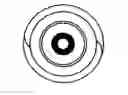
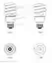
FIG. 1, FIG. 2 and FIG. 3 and FIG. 4 are the front view, left view, down view and up view of the lamp respectively.
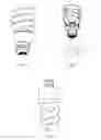
FIG. 5 is the overall view of the design,
FIG. 6 is the sectional view of this invention and view of the PC Board.
1 in FIG. 1 is the lamp base, 2 is the cover for the plastic housing, 3 is the lower part of the plastic housing and 4 is the spiral lamp tube.
5 in FIG. 6 is the PC Board.
6 in FIG. 6 are the two symmetrical notches on the board.
EMBODIMENTS OF THE INVENTIONFor this new practical invention, we only need to put the straight part of the lamp tube through the holes of the plastic housing and the notches on the PCB. The other aspects are the same to the other lamp designs.
Claims
What is claimed is:1. A new kind of fluorescent springlamp, which includes lamp base (1), lower part of the housing (2), upper cover for the housing (3), spiral lamp tube (4), the PCB that placed inside the plastic housing (5) and some other components. Among them, the legs of the tube with filaments in them are straight. The characteristics of this springlamp are there are two holes on the upper cover for the housing and two relative notches on the PCB (6). So the straight part of the tube can be completely placed in the plastic housing.
2. Depending on the springlamp described in claim 1 the characteristics are that the length of the straight part of the tube can be longer than the distance between the PCB in the plastic housing and the top of the housing.
Images & Drawings included:
Sources:
- United States Patent and Trademark Office - verify current appl. status at the USPTO↗
Recent applications in this class:
- » 20140043832 2014-02-13
Cover for a compact fluorescent light bulb - » 20120313521 2012-12-13
Heat shield on a compact fluorescent lamp - » 20120153804 2012-06-21
ULTRAVIOLET COLD CATHODE FLORESCENT LAMP - » 20120104948 2012-05-03
COMPACT FLUORESCENT LAMP WITH IMPROVED PERFORMANCE AND SIZE - » 20120020068 2012-01-26
High lumen output cold cathode fluorescent lamp - » 20120019136 2012-01-26
Compact fluorescent lamp with improved thermal management - » 20110304255 2011-12-15
Extended-life Lamp With Integral Cooling - » 20110298356 2011-12-08
POSITIONING OF AUXILIARY AMALGAM - » 20110291563 2011-12-01
Safety protection solution for compact fluorescent lamps - » 20110221344 2011-09-15
Compact fluorescent lamp operable in different power sources