Housing mechanism for electronic device
US20070189120A1
2007-08-16
11/616,821
2006-12-27
✅ Patent granted
US 7,697,269 B2
2010-04-13
-
-
Lisa Lea-Edmonds
2029-01-21
Abstract:
An exemplary housing mechanism (8) for an electronic device includes a cover (10) and a frame (20). The cover has a cover body (11), a sealing element (12), and a sidewall (13) formed around the cover body. A surface of a distal end of the sidewall is recessed thereby forming a receiving slot (16) therein. The sealing element has a connecting portion (122) and a positioning portion (124) connected to the connecting portion. The connecting portion is fixedly received in the receiving slot of the cover. The frame has a positioning slot (26) defined therein and the positioning portion of the sealing element is for reception in the positioning slot of the frame when the cover is closed to the frame.
Inventors:
- CHIA-HUA CHEN 58 🇹🇼 Shindian, Taiwan
- Qing YANG 42 🇨🇳 Shenzhen, China
- Chia-Hua Chen 12 🇹🇼 Taipei Hsien, Taiwan
Assignee:
- FIH (HONG KONG) LIMITED 1,465 🇭🇰 Kowloon, Hong Kong
- SUTECH TRADING LIMITED 185 Tortola, Virgin Islands (British)
- SHENZHEN FUTAIHONG PRECISION INDUSTRIAL CO,.LTD. 47 🇨🇳 Shenzhen, China
- ShenZhen FuTaiHong Precision Industry Co., Ltd. 446 🇨🇳 Shenzhen, Guangdong Province, China
Interested in similar patents?
Get notified when new applications in this technology area are published.
Classification:
H04M1/18 » CPC main
Substation equipment, e.g. for use by subscribers; Constructional features of telephone sets Telephone sets specially adapted for use in ships, mines, or other places exposed to adverse environment
B29C65/58 » CPC further
Joining of preformed parts ; Apparatus therefor using mechanical means or mechanical connections, e.g. form-fits Snap connection
B29C66/54 » CPC further
General aspects of processes or apparatus for joining preformed parts; General aspects of joining tubular articles; General aspects of joining long products, i.e. bars or profiled elements; General aspects of joining single elements to tubular articles, hollow articles or bars; General aspects of joining several hollow-preforms to form hollow or tubular articles; Joining tubular articles, profiled elements or bars; Joining single elements to tubular articles, hollow articles or bars; Joining several hollow-preforms to form hollow or tubular articles Joining several hollow-preforms, e.g. half-shells, to form hollow articles, e.g. for making balls, containers; Joining several hollow-preforms, e.g. half-cylinders, to form tubular articles
B29C66/542 » CPC further
General aspects of processes or apparatus for joining preformed parts; General aspects of joining tubular articles; General aspects of joining long products, i.e. bars or profiled elements; General aspects of joining single elements to tubular articles, hollow articles or bars; General aspects of joining several hollow-preforms to form hollow or tubular articles; Joining tubular articles, profiled elements or bars; Joining single elements to tubular articles, hollow articles or bars; Joining several hollow-preforms to form hollow or tubular articles; Joining several hollow-preforms, e.g. half-shells, to form hollow articles, e.g. for making balls, containers; Joining several hollow-preforms, e.g. half-cylinders, to form tubular articles joining hollow covers or hollow bottoms to open ends of container bodies
B29C45/14336 » CPC further
Injection moulding, i.e. forcing the required volume of moulding material through a nozzle into a closed mould; Apparatus therefor incorporating preformed parts or layers, e.g. injection moulding around inserts or for coating articles Coating a portion of the article, e.g. the edge of the article
B29C66/55 » CPC further
General aspects of processes or apparatus for joining preformed parts; General aspects of joining tubular articles; General aspects of joining long products, i.e. bars or profiled elements; General aspects of joining single elements to tubular articles, hollow articles or bars; General aspects of joining several hollow-preforms to form hollow or tubular articles; Joining tubular articles, profiled elements or bars; Joining single elements to tubular articles, hollow articles or bars; Joining several hollow-preforms to form hollow or tubular articles sealing elements being incorporated into the joints, e.g. gaskets
B29C2045/14459 » CPC further
Injection moulding, i.e. forcing the required volume of moulding material through a nozzle into a closed mould; Apparatus therefor incorporating preformed parts or layers, e.g. injection moulding around inserts or for coating articles; Coating a portion of the article, e.g. the edge of the article injecting seal elements
B29K2023/12 » CPC further
Use of polyalkenes or derivatives thereof as moulding material; Polymers of propylene PP, i.e. polypropylene
B29K2055/02 » CPC further
ABS polymers, i.e. acrylonitrile-butadiene-styrene polymers
B29K2069/00 » CPC further
Use of PC, i.e. polycarbonates or derivatives thereof , as moulding material
B29K2105/0079 » CPC further
Condition, form or state of moulded material or of the material to be shaped Liquid crystals
B29K2081/04 » CPC further
Use of polymers having sulfur, with or without nitrogen, oxygen or carbon only, in the main chain, as moulding material Polysulfides, e.g. PPS, i.e. polyphenylene sulfide or derivatives thereof
B29K2995/0069 » CPC further
Properties of moulding materials, reinforcements, fillers, preformed parts or moulds; Other properties; Permeability to liquids; Adsorption non-permeable
B29L2031/3431 » CPC further
Other particular articles; Electrical apparatus, e.g. sparking plugs or parts thereof Telephones, Earphones
B29K2081/06 » CPC further
Use of polymers having sulfur, with or without nitrogen, oxygen or carbon only, in the main chain, as moulding material PSU, i.e. polysulfones; PES, i.e. polyethersulfones or derivatives thereof
B29C66/71 » CPC further
General aspects of processes or apparatus for joining preformed parts characterised by the composition, physical properties or the structure of the material of the parts to be joined; Joining with non-plastics material characterised by the composition of the plastics material of the parts to be joined
B29K2079/085 » CPC further
PI, i.e. polyimides or derivatives thereof Thermoplastic polyimides, e.g. polyesterimides, PEI, i.e. polyetherimides, or polyamideimides; Derivatives thereof
B29K2079/08 » CPC further
PI, i.e. polyimides or derivatives thereof
B29K2067/003 » CPC further
Use of polyesters or derivatives thereof , as moulding material PET, i.e. poylethylene terephthalate
B29K2067/00 » CPC further
Use of polyesters or derivatives thereof , as moulding material
B29K2027/06 » CPC further
Use of polyvinylhalogenides or derivatives thereof as moulding material PVC, i.e. polyvinylchloride
B29K2025/06 » CPC further
Polymers of styrene PS, i.e. polystyrene
H04B11/00 IPC
Transmission systems employing sonic, ultrasonic or infrasonic waves
G06F1/16 IPC
Details not covered by groups - and Constructional details or arrangements
Description
BACKGROUND OF THE INVENTION
1. Field of the Invention
The present invention generally relates to electronic devices and, more particularly, to a housing mechanism for an electronic device configured (i.e., structured and arranged) for preventing water or dust from invading the electronic device.
2. Description of Related Art
With the development of wireless communication and information processing technologies, portable electronic devices such as notebook computers, mobile phones, and personal digital assistants (PDAs) are now in widespread use. These electronic devices enable consumers to enjoy high technology services anytime and anywhere.
Most contemporary electronic devices have little protection against water or dust. If the electronic devices drop into water, the electronic devices cannot be used because water may erode electronic elements of the electronic devices and cause short circuits. Some electronic devices have rubber plugs to protect against water or dust. However, the rubber plugs may easily become lost or fall out as they are small.
Therefore, a new housing mechanism for an electronic device is desired in order to overcome the above-described shortcomings.
SUMMARY OF THE INVENTION
In one aspect, a housing mechanism for an electronic device includes a cover and a frame. The cover has a cover body, a sealing element, and a sidewall formed around the cover body. A surface of a distal end of the sidewall is recessed thereby forming a receiving slot therein. The sealing element has a connecting portion and a positioning portion connected to the connecting portion. The connecting portion is fixedly received in the receiving slot of the cover. The frame has a positioning slot defined therein and the positioning portion of the sealing element is configured for reception in the positioning slot of the frame when the cover is closed to the frame.
Other advantages and novel features will become more apparent from the following detailed description when taken in conjunction with the accompanying drawings.
BRIEF DESCRIPTION OF THE DRAWINGS
Many aspects of the housing mechanism can be better understood with reference to the following drawings. The components in the drawings are not necessarily drawn to scale, the emphasis instead being placed upon clearly illustrating the principles of the present housing mechanism. Moreover, in the drawings, like reference numerals designate corresponding parts throughout the several views.
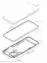
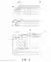
FIG. 1 is an exploded, schematic view of a housing mechanism in accordance with a preferred embodiment;
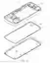
FIG. 2 is similar to FIG. 1 but viewed from another aspect;
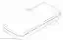
FIG. 3 is an assembled, schematic view of the housing mechanism in FIG. 1;
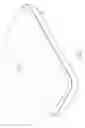
FIG. 4 is a partial, cross-sectional view of the housing mechanism along line IV-IV in FIG. 3; and
FIG. 5 is a exploded, cross-sectional view of the housing mechanism in FIG. 4.
DETAILED DESCRIPTION OF THE EMBODIMENT
Referring to FIG. 1, in a preferred embodiment, a housing mechanism 8 for an electronic device, such as a mobile phone, includes a cover 10 and a frame 20. An elastic sealing element 12 is integrally formed with the cover 10. For describing the structure of the housing mechanism 8, FIGS. 1-2 and 5 show exploded views of the housing mechanism 8, though the cover 10 and the elastic sealing element 12 are actually formed together.
Also referring to FIGS. 1-2 and 4-5, the cover 10 includes a cover body 11, the elastic sealing element 12, and a sidewall 13 formed around the cover body 11. The cover body 11 is a rectangular board in shape. A plurality of hooks 14 is formed on the cover body 11 adjacent to the sidewall 13. An inner surface of a distal end of the sidewall 13 away from the cover body 11 is recessed thereby forming two inclined surfaces 162. The two surfaces 162 are inclined at an angle relative to each other thereby forming a receiving slot 16 therebetween.
The sealing element 12 is a substantially quadrate hollow element and has a connecting portion 122 and a positioning portion 124 connected to the connecting portion 122 in a cross section thereof. The connecting portion 122 has two connecting surfaces 126. The two connecting surfaces 126 are inclined at an angle relative to each other. The connecting portion 122 is formed in the receiving slot 16 of the cover 10. Each connecting surface 126 abuts one corresponding inclined surface 162 of the cover 10. The connecting portion 122 and the positioning portion 124 are inclined at an angle relative to each other. The positioning portion 124 is substantially pillar-shaped. The sealing element 12 may advantageously be made of an elastic thermoplastic, such as thermoplastic urethanes (TPU). The sealing element 12 can also be made of elastic rubber.
The frame 20 is rectangular in shape. The frame 20 has a positioning slot 26 defined therein. The positioning slot 26 has a substantially V-shaped cross section. The positioning portion 124 of the sealing element 12 is configured for reception in the positioning slot 26. A plurality of projections 24 is formed on the frame 20 adjacent to the positioning slot 26. Each projection 24 defines a groove 242 therein. Each hook 14 is configured for reception in one corresponding groove 242.
The cover body 11, the sidewall 13, and the frame 20 may advantageously be made of a plastic material. The plastic material can be polyvinyl chloride, polyethylene terephthalate, acrylonitrile-butadiene-styrene, polycarbonate, polyimide, liquid crystal polymer, polyetherimide, polyphenylene sulfide, polysulfone, polystyrene, glycol-modified polyester, polypropylene, or any desired combination thereof.
Referring to FIGS. 3-4, in assembly, the positioning portion 124 of the sealing element 12 is deformed and pressed into the positioning slot 26 of the frame 20. The cover 10 and the frame 20 are locked together by means of the hooks 14 and the projections 24. In this way complete assembly of the housing mechanism 8 is achieved and a sealed inner space in which electronic components of the electronic device are accommodated is formed and surrounded by the sealing element 12 which prevents water or dust from invading the housing mechanism 8.
An exemplary method for making the housing mechanism 8 is provided. Firstly, a cover 10 is molded in a first mold by injection molding. The cover 10 has a receiving slot 16 defined therein and a plurality of hooks 14 formed thereon adjacent to the receiving slot 16. Secondly, an elastic sealing element 12 is molded in the receiving slot 16 of the cover 10 by injection molding. Thirdly, a frame 20 is molded in another mold by injection molding thus obtaining a housing mechanism 8 for an electronic device.
It is believed that the present embodiments and their advantages will be understood from the foregoing description, and it will be apparent that various changes may be made thereto without departing from the spirit and scope of the invention or sacrificing all of its material advantages, the examples here before described merely being preferred or exemplary embodiments of the invention.
Claims
What is claimed is:1. A housing mechanism for an electronic device, comprising:
a cover having a cover body, a sealing element, and a sidewall, the sidewall being formed around the cover body, a surface of a distal end of the sidewall being recessed to form a receiving slot therein, the sealing element having a connecting portion and a positioning portion connected to the connecting portion, the connecting portion being fixedly received in the receiving slot; and
a frame having a positioning slot defined therein and the positioning portion of the sealing element being configured for reception in the positioning slot of the frame when the cover is closed to the frame.
2. The housing mechanism as claimed in claim 1, wherein one of the cover and the frame has a hook formed thereon, the other of the cover and the frame has a groove defined therein, and the hook is configured for reception in the groove.
3. The housing mechanism as claimed in claim 1, wherein the distal end of the sidewall of the cover has two inclined surfaces and the two surfaces are inclined at an angle relative to each other thereby forming the receiving slot therebetween.
4. The housing mechanism as claimed in claim 3, wherein the connecting portion of the sealing element has two connecting surfaces, the two connecting surfaces are inclined at an angle relative to each other, and each connecting surface abuts one corresponding inclined surface of the cover.
5. The housing mechanism as claimed in claim 1, wherein the positioning slot of the frame has a substantially V-shaped cross section.
6. The housing mechanism as claimed in claim 5, wherein the positioning portion of the sealing element is substantially pillar-shaped before entering into the positioning slot of the frame and the positioning portion is deformed and pressed into the positioning slot of the frame.
7. The housing mechanism as claimed in claim 1, wherein the connecting portion and the positioning portion of the sealing element are inclined at an angle relative to each other.
8. The housing mechanism as claimed in claim 1, wherein the sealing element is made of an elastic material.
9. The housing mechanism as claimed in claim 8, wherein the sealing element is made of a material selected from the group consisting of rubber and thermoplastic urethanes (TPU).
10. The housing mechanism as claimed in claim 1, wherein the cover and the frame are made of plastic material.
11. The housing mechanism as claimed in claim 10, wherein the plastic material comprises at least one material selected from the group consisting of polyvinyl chloride, polyethylene terephthalate, acrylonitrile-butadiene-styrene, polycarbonate, polyimide, liquid crystal polymer, polyetherimide, polyphenylene sulfide, polysulfone, polystyrene, glycol-modified polyester, and polypropylene.
12. The housing mechanism as claimed in claim 1, wherein the sealing member is integrally formed in the receiving slot of the cover body via insert molding after the cover body and the sidewall are formed.
13. A housing mechanism for an electronic device, comprising:
a cover comprising a cover body, a sealing element, and a sidewall, the sidewall being integrally formed at a periphery of and surrounding the cover body, an inner surface of the sidewall being recessed to form two inclined surfaces with a receiving slot therebetween, the sealing element being received in the receiving slot and fixedly sandwiched between the two inclined surfaces, the sealing element comprising a positioning portion extending out of the receiving slot and surrounding the cover body; and
a frame having a positioning slot defined therein, the positioning portion of the sealing element being deformedly and interferentially received in the positioning slot of the frame to seal an inner space configured for accommodating electronic components of the electric device therein, the inner space being formed between the cover and frame and surrounded by the positioning portion and the sidewall.
14. The housing mechanism as claimed in claim 13, wherein the sealing member is integrally formed in the receiving slot of the cover body via insert molding after the cover body and the sidewall are formed.
15. The housing mechanism as claimed in claim 13, wherein a plurality of pairs of interlocking structures is formed between the cover and the frame for locking the cover with the frame.
16. The housing mechanism as claimed in claim 15, wherein each pair of interlocking structure comprises a hook formed on one of the cover and the frame, and a groove defined in the other of the cover and the frame, the hook being configured for reception in the groove.
17. The housing mechanism as claimed in claim 13, wherein the positioning slot of the frame has a substantially V-shaped cross section, and the positioning portion of the sealing element has a substantially pillar-shaped cross section before entering into the positioning slot, the positioning portion capable of being deformed and pressed into the positioning slot.
Images & Drawings included:

Sources:
- United States Patent and Trademark Office - verify current appl. status at the USPTO↗
Similar patent applications:
- » 20070171603
Housing mechanism for electronic device and method for making the same - » 20080232041
Housing mechanism and electronic device using the same - » 20220061173
Ventilation mechanism for electronic device housing - » 20250123502
JOINT MOUNTING MECHANISM FOR ELECTRONIC DEVICE HOUSING ASSEMBLY - » 20230403347
FOLDING MECHANISM, HOUSING APPARATUS, AND ELECTRONIC DEVICE - » 20230077824
Shaft mechanism for folding electronic device, housing assembly and electronic device - » 20140293535
Releasing mechanism for housing of portable electronic device - » 20170063422
Housing mounting mechanism for portable electronic device - » 20080192455
Housing mechanism with shield for portable electronic device - » 20080239633
HOUSING MECHANISM WITH HOOK FOR PORTABLE ELECTRONIC DEVICE
Recent applications in this class:
- » 20250280064 2025-09-04
SUN SHADE FOR CELL PHONES - » 20250211667 2025-06-26
ELECTRONIC DEVICE WITH WATERPROOF STRUCTURE - » 20250175549 2025-05-29
ELECTRONIC APPARATUS - » 20250008013 2025-01-02
ELECTRONIC DEVICE COMPRISING STRUCTURE FOR PREVENTING INTRODUCTION OF FOREIGN MATTER - » 20240348712 2024-10-17
UNDERWATER COMMUNICATION INTERFACE APPARATUS - » 20240205322 2024-06-20
ELECTRONIC DEVICE INCLUDING WATERPROOF STRUCTURE - » 20240205321 2024-06-20
Method, Apparatus and Device for Identifying Water Ingress Risk of Terminal, and Storage Medium - » 20230051260 2023-02-16
ELECTRONIC DEVICE INCLUDING WATERPROOF STRUCTURE - » 20230046954 2023-02-16
Electronic device with waterproof structure - » 20220400171 2022-12-15
ELECTRONIC DEVICE INCLUDING ANTENNA MODULE
Recent applications for this Assignee:
- » 20220140846 2022-05-05
Antenna structure and wireless communication device using same - » 20220094077 2022-03-24
Antenna structure and wireless communication device using same - » 20220059931 2022-02-24
Antenna structure and wireless communication device - » 20220021116 2022-01-20
Single antenna structure capable of operating in multiple band widths - » 20220010948 2022-01-13
Anti-loosing structure and backlight module - » 20200170133 2020-05-28
Housing, electronic device, and method for manufacturing same - » 20200122194 2020-04-23
Frame and surface treatment method for the frame - » 20200060034 2020-02-20
Housing, method for manufacturing the same, and electronic device having the same - » 20200016805 2020-01-16
Housing, electronic device, and method for manufacturing the same - » 20190368052 2019-12-05
COMPOSITE AND METHOD FOR MAKING SAME