Burning wick structure
US20070190472A1
2007-08-16
11/354,843
2006-02-16
Abstract:
A burning wick structure includes an upper half portion and a lower half portion. The outer diameter of the upper half portion is larger than that of the lower half portion. The bottom surface of the lower half portion is provided with an insertion hole for being inserted by an end of a cotton thread. The top portion of the insertion hole is further provided with an evaporating region. A porous region having a larger thickness is formed between the evaporating region and the top portion of the upper half portion. The porous region is formed with at least one ventilating region having a smaller thickness.
Interested in similar patents?
Get notified when new applications in this technology area are published.
Classification:
F23D3/18 » CPC main
Burners using capillary action; Wick burners Details of wick burners
Description
BACKGROUND OF THE INVENTION1. Field of the Invention
The present invention relates to a burning wick structure, and in particular to a burning wick structure, which is safe to use without hindering the catalytic burning.
2. Description of Prior Art
Ceramics are water-absorbent by its physical nature, and thus also inherently have porosity and water-absorbency. For example, the standards of purchasing ceramic tiles and bricks must specify the range of the percentage of absorbing water. It is apparent that the water-absorbency of the ceramics is well known.
As disclosed in Taiwan Patent Publication No.474839 entitled “Catalytic Burning Nozzle Having Porous Material”, an open channel is provided on a nozzle, and the channel is in communication with the atmosphere through a hollow portion within the nozzle in order not to hinder the catalytic burning. However, such a conventional structure is prone to be potential dangerous since the burning liquid may spill out through the channel when a user accidentally turns over the burning device containing essential oil therein. Further, when in use, since the isopropyl alcohol contained in the burning liquid may burn insufficiently when heated, the isopropyl alcohol may escape from the open channel to be breathed in the human body. Therefore, such a conventional structure is not safe to use and seriously affects the health of the human body.
In view of the above, the inventor attempts to overcome the foregoing drawbacks, employs related principles and thus provides a feasible design to efficiently improve the above drawbacks.
SUMMARY OF THE INVENTIONThe present invention is to provide a burning wick structure, which is safe to use without hindering the normal effect of the catalytic burning. Further, the possibility of fire caused by accidentally turning over the burning device can be avoided, so that the potential danger of the burning wick can be greatly reduced. Moreover, the insufficient burning of the burning liquid can be effectively improved to avoid the exhausted isopropyl alcohol from being breathed in the human body to affect the heath.
Accordingly, the present invention provides a burning wick structure comprising an upper half portion and a lower half portion. The outer diameter of the upper half portion is larger than that of the lower half portion. The bottom surface of the lower half portion is provided with an insertion hole for being inserted by an end of a cotton thread The top portion of the insertion hole is further provided with an evaporating region. A porous region having a larger thickness is formed between the evaporating region and the top portion of the upper half portion. The porous region is formed with at least one ventilating region having a smaller thickness.
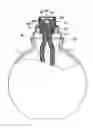
BRIEF DESCRIPTION OF THE DRAWINGSFIG. 1 is a perspective view showing the external appearance of the burning device of the present invention;
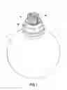
FIG. 2 is a partial cross-sectional view of the burning device of the present invention;
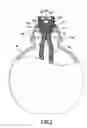
FIG. 3 is a schematic view showing the external appearance of the burning wick of a first embodiment of the present invention;
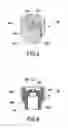
FIG. 4 is a schematic cross-sectional view showing the burning wick of the first embodiment of the present invention;
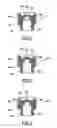
FIG. 5 is a schematic cross-sectional view showing the burning wick of a second embodiment of the present invention;
FIG. 6 is a schematic cross-sectional view showing the burning wick of a third embodiment of the present invention; and
FIG. 7 is a schematic cross-sectional view showing the burning wick of a fourth embodiment of the present invention.
DETAILED DESCRIPTION OF THE INVENTIONIn order to make the Examiner further understand the present invention, the characteristics and the technical contents of the present invention will be explained with reference to the detailed description and the accompanying drawings. However, it should be understood that the drawings are illustrative but not used to limit the scope of the present invention.
FIG. 1 is a perspective view showing the external appearance of the burning device of the present invention, and FIG. 2 is a partial cross-sectional view of the burning device of the present invention. The present invention provides an improved structure of burning wick. The burning wick 10 is used for being arranged on a burning device 1 (such as an essential oil lamp). The burning device 1 mainly includes a hollow bottle body 11, a mouth cap 12 provided on a mouth 110 of the bottle body 11, a heat-resistant ring 13 provided on the top portion of the mouth cap 12, and the burning wick 10. The burning wick 10 is supported on the heat-resistant ring 13, and in turn is supported on the top portion of the mouth cap 12 by the heat-resistant ring 13 to expose outside. The lower portion of the burning wick 10 is connected to both ends of a cotton thread 14, so that the cotton thread 14 is suspended within the bottle body 11. With the above arrangement, the burning liquid (not shown, such as essential oil) within the bottle body 11 can be introduced to the burning wick 10 via the absorption of the cotton thread 14.
With reference to FIGS. 3 and 4, the present invention lies in that the burning wick 10 is formed of a ceramic material with an upper half portion 100 and a lower half portion 101. The outer diameter of the upper half portion 100 is larger than that of the lower half portion 101. A narrowed neck portion 102 is formed between the upper half portion 100 and a lower half portion 101, so that the burning wick 10 can be supported on the heat-resistant ring 13. The bottom surface of the lower half portion of the burning wick 10 is provided with an insertion hole 103. The insertion hole 103 is a blind hole used for being inserted by one end of the cotton thread 14. The top portion of the insertion hole 103 is further provided with an evaporating region 104. A porous region 105 having a larger thickness is formed between the evaporating region 104 and the top portion of the upper half portion 100. The porous region 105 is formed with at least one ventilating region 106 having a smaller thickness.
In the present embodiment, the ventilating region 106 is formed in such a manner that a recess 107 is recessed downwardly at the top surface of the upper half portion 100 with respect to the evaporating region 104. The recess 107 can be a circular groove or blind hole for narrowing the thickness of the ventilating region 106. As a result, the thickness of the porous region 105 becomes smaller in the ventilating region 106. With the smaller thickness, the external air can still enter the evaporating region 104 via the ventilating region 106 without hindering the catalytic burning. At the same time, owing to the formation of the ventilating region 106, when the user accidentally turns over the burning device 1, the ventilating region 106 can protect the burning liquid within the bottle body 11 from spilling out. Therefore, the spilled burning liquid can be avoided from burning, producing the safety in use.
Further, as shown in FIG. 5, the ventilating region 106 can be formed in such a manner that a recess 107 is recessed upwardly at the top surface of the evaporating region 104. Further, as shown in FIG. 6, the ventilating region 106 can be formed in such a manner that each recess 107 is recessed at the top surfaces of the upper half portion 100 and the evaporating region 104, respectively. Further, as shown in FIG. 7, the ventilating region 106 can be even formed by recessing a plurality of recesses 107.
Therefore, with the above arrangement, the improved structure of burning wick of the present invention can be achieved.
With the improved structure of burning wick of the present invention, it is safe in use without hindering the normal effect of the catalytic burning. Further, the possibility of fire caused by accidentally turning over the burning device can be avoided, so that the potential danger of the burning wick can be greatly reduced. Moreover, the insufficient burning of the burning liquid can be effectively improved to avoid the exhausted isopropyl alcohol from being breathed in the human body to affect the health
According to the above, the present invent is a novel product capable of achieving the expected purposes. Further, it has overcome the drawbacks of conventional art and thus has industrial applicability, novelty and inventive steps, indeed conforming to the requirements for a utility model patent.
Although the present invention has been described with reference to the foregoing preferred embodiments, it will be understood that the invention is not limited to the details thereof Various equivalent variations and modifications can still be occurred to those skilled in this art in view of the teachings of the present invention. Thus, all such variations and equivalent modifications are also embraced within the scope of the invention as defined in the appended claims.
Claims
What is claimed is:1. A burning wick structure, comprising an upper half portion and a lower half portion, wherein an outer diameter of the upper half portion is larger than that of the lower half portion, a bottom surface of the lower half portion is provided with an insertion hole for being inserted by an end of a cotton thread; and wherein a top portion of the insertion hole is further provided with an evaporating region, a porous region having a larger thickness is formed between the evaporating region and the top portion of the upper half portion, and the porous region is formed with at least one ventilating region having a smaller thickness.
2. The burning wick structure according to claim 1, wherein the burning wick is formed of a ceramic material.
3. The burning wick structure according to claim 1, wherein a narrowed neck portion is formed between the upper half portion and the lower half portion.
4. The burning wick structure according to claim 1, wherein the insertion hole is a blind hole.
5. The burning wick structure according to claim 1, wherein the ventilating region is formed in such a manner that a recess is recessed downwardly at the top surface of the upper half portion with respect to the evaporating region.
6. The burning wick structure according to claim 1, wherein the ventilating region is formed in such a manner that a recess is recessed upwardly at a top surface of the evaporating region.
7. The burning wick structure according to claim 6, wherein the recess is a groove or a blind hole.
8. The burning wick structure according to claim 1, wherein the ventilating region is formed in such a manner that each recess is recessed at a top surfaces of the upper half portion and the evaporating region, respectively.
9. The burning wick structure according to claim 8, wherein the recess is a groove or a blind hole.
10. The burning wick structure according to claim 5, wherein the recess is a groove or a blind hole.
Images & Drawings included:
Sources:
- United States Patent and Trademark Office - verify current appl. status at the USPTO↗
Similar patent applications:
Recent applications in this class:
- » 20230228414 2023-07-20
COMBUSTION SYSTEM AND METHOD OF OPERATION THEREOF - » 20220228740 2022-07-21
SUSTAINABLE CANDLES AND METHODS - » 20220136695 2022-05-05
METHOD FOR MANUFACTURING A CANDLE HAVING AN ITEM EMBEDDED WITHIN - » 20200408401 2020-12-31
Method for manufacturing a candle having an item embedded within - » 20200200382 2020-06-25
Combustion Device Capable of Avoiding Overheat - » 20190338946 2019-11-07
Catalytic combustion burner made of porous material, with optimised operating performance and bottle equipped with such a burner - » 20190120484 2019-04-25
Candle with embedded item and methods for manufacturing and selling same - » 20190101281 2019-04-04
Fire display device - » 20180266677 2018-09-20
Wick of flame device - » 20170299174 2017-10-19
FUEL CELL SYSTEM