Crossing Guard
US20070194291A1
2007-08-23
11/307,717
2006-02-17
Abstract:
There is a protective cover for securing to wire fencing. There are first and second elongated shielding members that are removably coupleable one to another forming a tube. There is a locking member that is removably coupleable to the first and second elongated shielding members at an interface between the first and second elongated shielding members, thereby restricting separation. There are interlocking slots and interlocking protrusions that extending laterally along each of the first and second elongated shielding members. The two shielding member may be slid apart and may be pressed together. The locking member is a threaded plug coupleable to a void through the first and second elongated shielding members at the interlocking slot and interlocking protrusion. The void includes a narrowed seating portion disposed adjacent internal the tube and configured to restrict the locking plug from entering the tube.
Interested in similar patents?
Get notified when new applications in this technology area are published.
Classification:
A01K3/00 » CPC further
Pasturing equipment, e.g. tethering devices; Grids for preventing cattle from straying; Electrified wire fencing
E04H17/04 » CPC main
Fencing, e.g. fences, enclosures, corrals; Wire fencing, e.g. made of wire mesh characterised by the use of specially adapted wire, e.g. barbed wire, wire mesh, toothed strip or the like; Coupling means therefor
Description
BACKGROUND OF THE INVENTION1. Field of the Invention
The present invention relates to protective covers, specifically to protective covers for securing to wire fencing.
2. Description of the Related Art
Wire fencing is typically used for control of boundaries, especially with respect to controlling behavior of animals. The types of wire fencing are plethoric, but some examples of broad categories of fencing include but are not limited to barbed wire fencing and electric fencing. Electric fencing as used in this specification is defined as fencing including an electrical component intended to cause discomfort on contact but not to such a degree as to be injurious and/or life threatening. Both categories of fencing function to provide a boundary enforced by a potential of inflicting substantial discomfort on those who would try and cross the boundary. Accordingly, animals learn to respect the boundary and may thereby be controlled.
However, such boundaries are typically inconvenient for people such as ranchers and others who may have work to accomplish. While the boundaries may be crossed by humans, there is generally a certain risk associated with crossing the boundaries. There may be failures in judgment, perhaps caused by unfamiliarity with the fencing, the ground surrounding the fencing, by fatigue from hard labor, by a need to hurry, and/or by changed environmental conditions such as a hard rain. In such cases, a person may be subjected to the enforcement potential of the fencing which may include electrical shock, puncturing of skin and other tissue, entanglement, etc.
There have been attempts to provide a measure of safety for people crossing these types of fencing. In particular, U.S. Pat. No. 5,340,086 to Dorr discloses a protective device for covering a barb in a strand of barbed wire is disclosed. The barb has a plurality of outwardly extending points disposed around the strand with the strand extending axially outwardly from opposing sides of the barb. In a first embodiment, the protective covering device of the present invention has an upper shell formed in a substantial hemisphere and a lower shell formed in a substantial hemisphere. A color agent may be optionally added to the upper and lower shells in order to provide high visibility when attached over the barb. A living hinge connects the upper and lower shells in a pivoting relationship so that the upper shell can pivot towards to lower shell. Male and female locking elements are provided on the upper and lower shells for locking the two hemispheres together over the barb. When locked, the barb is located in a formed hollow interior of the two shells and is fully protected from causing damage to animals and the like. The upper and lower shells have formed angular opening on opposing sides thereof so as to permit the passage of the strand through the protective covering device. A second embodiment, a solid material, is placed or injected over the barb covering the extending points as well as a portion of the strand.
In another example, US Patent Application No. 2004/0012006 by Petroziello discloses a protective guard securable over an upper edge of a fence includes an elongated member, such as an elongated tube, having first and second ends, an outer surface, an inner surface defining an interior space and an elongated opening extending between the inner and outer surfaces and the first and second ends of the elongated member, and first and second attachment flanges integrally formed with the elongated tube on opposite sides of the elongated opening, the first and second attachment flanges being adapted for engaging opposite sides of the fence when the protective guard is secured atop the fence. The protective guard may also include at least one securing element in contact with the first and second attachment flanges for securing the attachment flanges together on opposite sides of the fence.
What is needed is a protective cover that solves one or more of the problems described herein and/or one or more problems that may come to the attention of one skilled in the art upon becoming familiar with this specification.
SUMMARY OF THE INVENTIONThe present invention has been developed in response to the present state of the art, and in particular, in response to the problems and needs in the art that have not yet been fully solved by currently available protective cover. Accordingly, the present invention has been developed to provide a protective cover for securing to a wire fence.
In one embodiment, there is a protective cover for securing to wire fencing. There may be first and second elongated shielding members that may be removably coupleable one to another according to a first mode of removability. The first and second elongated shielding members may form a tube. There may be a locking member that may be removably coupleable to the first and second elongated shielding members at an interface between the first and second elongated shielding members, thereby restricting the first mode of removability. The first and second elongated shielding members may each include an interlocking slot and/or an interlocking protrusion that may extend laterally along each of the first and second elongated shielding members. The first mode of removability may comprise lateral sliding of the first and second elongated shielding members with respect of one to the other.
The locking member may comprise a threaded plug that may be threadably coupleable to a void through the first and second elongated shielding members at the interlocking slot and interlocking protrusion. The void may include a narrowed seating portion disposed adjacent internal the tube and configured to restrict the locking plug from entering the tube. The first and second elongated members may be substantially flexible such that each of the interlocking slots and each of the interlocking protrusions may be coupled by pressing the first elongated member to the second elongated member.
Reference throughout this specification to features, advantages, or similar language does not imply that all of the features and advantages that may be realized with the present invention should be or are in any single embodiment of the invention. Rather, language referring to the features and advantages is understood to mean that a specific feature, advantage, or characteristic described in connection with an embodiment is included in at least one embodiment of the present invention. Thus, discussion of the features and advantages, and similar language, throughout this specification may, but do not necessarily, refer to the same embodiment.
Furthermore, the described features, advantages, and characteristics of the invention may be combined in any suitable manner in one or more embodiments. One skilled in the relevant art will recognize that the invention can be practiced without one or more of the specific features or advantages of a particular embodiment. In other instances, additional features and advantages may be recognized in certain embodiments that may not be present in all embodiments of the invention.
These features and advantages of the present invention will become more fully apparent from the following description and appended claims, or may be learned by the practice of the invention as set forth hereinafter.
BRIEF DESCRIPTION OF THE DRAWINGSIn order for the advantages of the invention to be readily understood, a more particular description of the invention briefly described above will be rendered by reference to specific embodiments that are illustrated in the appended drawings. Understanding that these drawings depict only typical embodiments of the invention and are not therefore to be considered to be limiting of its scope, the invention will be described and explained with additional specificity and detail through the use of the accompanying drawings, in which:
FIG. 1 illustrates a side perspective view of a protective cover according to one embodiment of the invention;
FIG. 2 illustrates a side plan view of a protective cover according to one embodiment of the invention; and
FIG. 3 illustrates a side view of a protective cover in use according to one embodiment of the invention.
DETAILED DESCRIPTION OF THE INVENTIONFor the purposes of promoting an understanding of the principles of the invention, reference will now be made to the exemplary embodiments illustrated in the drawings, and specific language will be used to describe the same. It will nevertheless be understood that no limitation of the scope of the invention is thereby intended. Any alterations and further modifications of the inventive features illustrated herein, and any additional applications of the principles of the invention as illustrated herein, which would occur to one skilled in the relevant art and having possession of this disclosure, are to be considered within the scope of the invention.
Reference throughout this specification to “one embodiment,” “an embodiment,” or similar language means that a particular feature, structure, or characteristic described in connection with the embodiment is included in at least one embodiment of the present invention. Thus, appearances of the phrases “one embodiment,” “an embodiment,” and similar language throughout this specification may, but do not necessarily, all refer to the same embodiment, different embodiments, or component parts of the same or different illustrated invention. Additionally, reference to the wording “an embodiment,” or the like, for two or more features, elements, etc. does not mean that the features are related, dissimilar, the same, etc. The use of the term “an embodiment,” or similar wording, is merely a convenient phrase to indicate optional features, which may or may not be part of the invention as claimed.
Each statement of an embodiment is to be considered independent of any other statement of an embodiment despite any use of similar or identical language characterizing each embodiment. Therefore, where one embodiment is identified as “another embodiment,” the identified embodiment is independent of any other embodiments characterized by the language “another embodiment.” The independent embodiments are considered to be able to be combined in whole or in part one with another as the claims and/or art may direct, either directly or indirectly, implicitly or explicitly.
Finally, the fact that the wording “an embodiment,” or the like, does not appear at the beginning of every sentence in the specification, such as is the practice of some practitioners, is merely a convenience for the reader's clarity. However, it is the intention of this application to incorporate by reference the phrasing “an embodiment,” and the like, at the beginning of every sentence herein where logically possible and appropriate.
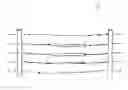
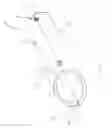
Turning to the figures, there is shown here is a protective cover 100 for securing to a wire or strand of wire fencing. Wire fencing includes boundaries defined by one or more strands or wires. There are illustrated first and second elongated shielding members 110 and 120 that are removably coupleable one to another according to a first mode of removability. The illustrated first mode of removability includes lateral sliding apart of shielding members 110 and 120 as shown by arrows 150. In one example, arrows 150 may be reversed. Other modes of removability are contemplated, including but not limited to pulling, pressing, unlocking, de-latching, and detaching.
The first and second elongated shielding members 110 and 120 illustrated form a tube. There is shown a locking member 140 that is removably coupleable to the first and second elongated shielding members 110 and 120 at an interface between the first and second elongated shielding members 102, thereby restricting the shielding members 110 and 120 from laterally sliding when the locking member 140 is in place. As is more clearly shown in blow up portion 240, the first and second elongated shielding members 110 and 120 each include an interlocking slot 222 and an interlocking protrusion 222 that extend laterally along each of the first and second elongated shielding members 110 and 120. The illustrated first mode of removability comprises lateral sliding 150 of the first and second elongated shielding members 110 and 120 with respect of one to the other.
The illustrated locking member 140 comprises a threaded plug 140 threadably coupleable to a void 130 through the first and second elongated shielding members 110 and 120 at the interlocking slot 222 and interlocking protrusion 222. The illustrated void 130 includes a narrowed seating portion 230 disposed adjacent internal 210 the tube and configured to restrict the locking plug 140 from entering internal 210 the tube. The first and second elongated members 110 and 120 may be substantially flexible such that each of the interlocking slots 222 and each of the interlocking protrusions 222 may be coupled by pressing the first elongated member 110 to the second elongated member 120, wherein the interlocking members 222 may bend, expand, contract, etc. to accommodate moving to an interlocking position.
It is preferred that the protective cover 100 be smooth thereby preventing a user from catching on the cover. It is preferred that an internal diameter 230 of the protective cover be greater than a radial length of a barb on the barb wire fence (the maximum radial extension of a barb from a wire). It is preferred that the protective cover 100 be made of a non-conductive material such as but not limited to plastic wherein the protective cover is intended to be used to cover a strand of an electric fence.
In operation, a user may couple the protective cover 100 to a wire, thereby shielding the wire from the user. Accordingly, a user may interface with the wire, such as moving over and/or under the wire without fear of being hurt, damaged, and/or inconvenienced by the wire and without damaging the fence. In the example illustrated in FIG. 3, a user may us a plurality of protective covers 100, such as but not limited to covering adjacent wires, thereby providing a pair of wires through which passage may be made without risk of an unpleasant interaction with the pair of wires.
It is understood that the above-described preferred embodiments are only illustrative of the application of the principles of the present invention. The present invention may be embodied in other specific forms without departing from its spirit or essential characteristics. The described embodiment is to be considered in all respects only as illustrative and not restrictive. The scope of the invention is, therefore, indicated by the appended claim rather than by the foregoing description. All changes which come within the meaning and range of equivalency of the claims are to be embraced within their scope.
For example, although the figures illustrate a tube having a circular cross section, it is envisioned that the tube may include cross section(s) of other shapes including irregular shapes.
Additionally, although the figures illustrate a pair of voids through the tube, there may be only a single void and locking member. There may be a plurality of voids and locking members. There may be four voids and four locking members. Still more, while the interface portions 102 are illustrated as being substantially on opposite sides of the tube, it is envisioned that interface portions whereat shielding members 110 and 120 meet and/or couple may be at any radial angle around the tube.
It is also envisioned that locking members and voids may be configured to prevent other and/or additional modes of removability. In one example, a void may extend through a tube at an interlocking boundary substantially perpendicular to each of the long axis of the tube and the orientation of the illustrated void. Accordingly, when a corresponding locking member may be coupled thereto, such may prevent a plurality of modes of removability or separation.
It is expected that there could be numerous variations of the design of this invention. While the illustrated locking member includes a slot for a flat head screwdriver, another exemplary locking member may include a thumb screw interface such that the locking member may be locked and/or unlocked by hand.
Finally, it is envisioned that the components of the device may be constructed of a variety of materials, including but not limited to plastic, resin, wood, metal, ceramic, composite, fiber, and combinations thereof.
Thus, while the present invention has been fully described above with particularity and detail in connection with what is presently deemed to be the most practical and preferred embodiment of the invention, it will be apparent to those of ordinary skill in the art that numerous modifications, including, but not limited to, variations in size, materials, shape, form, function and manner of operation, assembly and use may be made, without departing from the principles and concepts of the invention as set forth in the claims.
Claims
What is claimed is:1. A protective cover for securing to wire fencing, comprising:
first and second elongated shielding members removably coupleable one to another according to a first mode of removability, thereby forming a tube; and
a locking member removably coupleable to the first and second elongated shielding members at an interface between the first and second elongated shielding members, thereby restricting the first mode of removability.
2. The protective cover of claim 1, wherein the first and second elongated shielding members each include an interlocking slot and an interlocking protrusion extending laterally along each of the first and second elongated shielding members and wherein the first mode of removability is lateral sliding of the first and second elongated shielding members with respect of one to the other.
3. The protective cover of claim 2, wherein the locking member comprises a threaded plug threadably coupleable to a void through the first and second elongated shielding members at the interlocking slot and interlocking protrusion.
4. The protective cover of claim 3, wherein the void comprises a narrowed seating portion disposed adjacent internal the tube and configured to restrict the locking plug from entering the tube.
5. The protective cover of claim 4, wherein the first and second elongated members are substantially flexible such that each of the interlocking slots and each of the interlocking protrusions may be coupled by pressing the first elongated member to the second elongated member.
6. A protective cover for securing to wire fencing, consisting essentially of:
first and second elongated shielding members removably coupleable one to another according to a first mode of removability, thereby forming a tube; and
a locking member removably coupleable to the first and second elongated shielding members at an interface between the first and second elongated shielding members, thereby restricting the first mode of removability.
7. The protective cover of claim 6, wherein the first and second elongated shielding members each include an interlocking slot and an interlocking protrusion extending laterally along each of the first and second elongated shielding members and wherein the first mode of removability is lateral sliding of the first and second elongated shielding members with respect of one to the other.
8. The protective cover of claim 7, wherein the locking member comprises a threaded plug threadably coupleable to a void through the first and second elongated shielding members at the interlocking slot and interlocking protrusion.
9. The protective cover of claim 8, wherein the void comprises a narrowed seating portion disposed adjacent internal the tube and configured to restrict the locking plug from entering the tube.
10. The protective cover of claim 9, wherein the first and second elongated members are substantially flexible such that each of the interlocking slots and each of the interlocking protrusions may be coupled by pressing the first elongated member to the second elongated member.
Images & Drawings included:


Sources:
- United States Patent and Trademark Office - verify current appl. status at the USPTO↗
Similar patent applications:
- » 20060031002
School crossing guard, security system - » 20080248170
Re-usable toy candy stick with a holding ring and a cross guard plate - » 20170149803
Guarding against cross-site request forgery (CSRF) attacks - » 20080053694
Double comb guard trace pattern for reducing the far-end cross-talk and printed circuit board including the pattern
Recent applications in this class:
- » 20230125612 2023-04-27
FENCE SUPPORT SYSTEM - » 20220396969 2022-12-15
ROBOTIC LAWNMOWER FENCE - » 20220333401 2022-10-20
Vertical cable rail barrier - » 20220220763 2022-07-14
Animal repellent products, repellent compositions and methods of manufacturing the same - » 20210388632 2021-12-16
Mesh fence material and method for making thereof - » 20210123263 2021-04-29
Vertical cable rail barrier - » 20200149308 2020-05-14
Razor wire fence panel - » 20190085586 2019-03-21
FENCE SUPPORT SYSTEM - » 20190032362 2019-01-31
Barb tape and barb tape panel - » 20170362854 2017-12-21
Vertical cable rail barrier