Arthroscopic fluid control device
US20070239113A1
2007-10-11
11/730,944
2007-04-05
✅ Patent granted
US 7,785,287 B2
2010-08-31
-
-
Nicholas D Lucchesi | Ian K Holloway
2028-10-17
Abstract:
The fluid control device is attached to tubes carrying irrigation solution to form the system. The control device splits the flow through a fiber optic scope and a fluid control unit. The fluid control unit controls rate of flow and direction. The flow of fluid into the joint, out of the joint, or no flow is easily controlled by the operator. The device also allows more than one inflow, useful when using suction or suction shaving devices. The increased flow prevents collapse of a joint space and maintains clear visualization. The fluid flow relies on gravity by having a fluid reservoir positioned at a high point in the system.
Interested in similar patents?
Get notified when new applications in this technology area are published.
Classification:
A61M3/0241 » CPC main
Medical syringes, e.g. enemata; Irrigators; Enemata; Irrigators characterised by liquid supply means, e.g. from pressurised reservoirs the liquid being supplied by gravity
A61M3/0208 » CPC further
Medical syringes, e.g. enemata; Irrigators; Enemata; Irrigators; Physical characteristics of the irrigation fluid, e.g. conductivity or turbidity before use
A61M3/0212 » CPC further
Medical syringes, e.g. enemata; Irrigators; Enemata; Irrigators; Physical characteristics of the irrigation fluid, e.g. conductivity or turbidity after use
A61M3/0216 » CPC further
Medical syringes, e.g. enemata; Irrigators; Enemata; Irrigators; Physical characteristics of the irrigation fluid, e.g. conductivity or turbidity Pressure
A61M3/022 » CPC further
Medical syringes, e.g. enemata; Irrigators; Enemata; Irrigators; Physical characteristics of the irrigation fluid, e.g. conductivity or turbidity Volume; Flow rate
A61M39/223 » CPC further
Tubes, tube connectors, tube couplings, valves, access sites or the like, specially adapted for medical use; Valves or arrangement of valves Multiway valves
A61M2039/224 » CPC further
Tubes, tube connectors, tube couplings, valves, access sites or the like, specially adapted for medical use; Valves or arrangement of valves; Multiway valves of the slide-valve type
A61M37/00 IPC
Other apparatus for introducing media into the body ; Percutany, i.e. introducing medicines into the body by diffusion through the skin
A61B17/20 IPC
Surgical instruments, devices or methods, e.g. tourniquets for vaccinating or cleaning the skin previous to the vaccination
Description
This application claim benefit of provisional application 60/789,598, filed Apr. 6, 2006.
BACKGROUND OF THE INVENTION
During arthroscopic surgery the flow of fluids and suction to the site must be controlled based on the surgeon's needs. Normally, fluid control is achieved with the use of a mechanical pump. Mechanical pumps have high initial costs plus maintenance costs and there is always the possibility that, during surgery, a pump will fail. There is always a risk of electric conduction injury and a risk of compartment syndrome where fluid pressure in a compartment exceeds venous pressure causing a loss of circulation to a limb or muscle group. This risk can be even greater with some of the current mechanical fluid systems when fluid leaks into spaces outside the joint as occurs in acute trauma when there is communication between the joint and local soft tissue. The invention gravity controlled positive pressure, in combination with the various modes of flow, reduces this risk and can eliminate the need for a tourniquet, thereby also reducing tourniquet related injuries due to vascular compromise and post operative lactic acid accumulation in a limb.
There is a need in the art for a fluid control device not relying on a mechanical pump that provides adequate flow, control of direction of the flow and control of the flow rate.
Existing electromechanical system are based on constant pressure or constant flow. The invention has distinct advantages over such a system because it only replenishes fluid that flows out of the joint, decreasing the amount of soft tissue swelling during the course of the procedure. Also, the gravity based system creates positive pressure environment in the joint to decrease intraarticular bleeding. Also, the system has multiple modes of flow allowing for more ways to clear intraarticular debris in the joint.
SUMMARY OF THE INVENTION
The fluid control device is attached to tubes carrying irrigation solution to form the system. The control device splits the flow through a fiber optic scope and a fluid control unit. The fluid control unit controls rate of flow and direction. The flow of fluid into the joint, out of the joint, or no flow is easily controlled by the operator. The device also allows more than one inflow, useful when using suction or suction shaving devices. The increased flow prevents collapse of a joint space and maintains clear visualization. The fluid flow relies on gravity by having a fluid reservoir positioned at a high point in the system.
BRIEF DESCRIPTION OF THE DRAWINGS
FIG. 1 shows the fluid control device in each of three positions;
FIG. 2 shows views of the fluid control device; and
FIGS. 3-8 show the system in various modes used during surgery.
DETAILED DESCRIPTION OF THE INVENTION
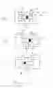
FIG. 1 shows a fluid control device 10 having three ports 12, 14, 16. A slider is positioned between the two ports 12, 14. In FIG. 1A, the slider 18 is in the central position and there is no fluid communication between any ports. In FIG. 1B, the slider is moved to the right position and fluid flows between ports 12 through port 16. In FIG. 1C, a slider is moved to the left position and there is fluid communication between the port 16 and port 14.
FIG. 2 shows the front rear end perspective view of the fluid control device. In the front view, the slider and port 16 are seen. In the rear view, the ports 12 and 14 are seen, as well as the slider. This perspective view shows all three ports 12, 14, 16 and the slider 18.
FIG. 3 shows the complete fluid control system, with fluid reservoirs 20 each having an outlet line 22 connected to a fluid divider, such as a Y junction 24, with line 26 leading from the Y junction 24 to a second Y junction 28. A single reservoir may be used which would be connected to the line 26. A first line 30 leads from the Y junction 28 to an arthroscope 32. A second line 34 extends from the Y junction 28 to the port 12 on the fluid control device 10. Leading from the port 16 is a line 36 terminating in a flow port cannula 38. A drain line 40 is connected to port 14 and leads to a gravity drainage 42.
The various modes of operation of the system, including the control device 10, are seen in FIGS. 4-8. FIG. 4 shows a dual inflow operation with flow extending through ports 12 and out port 16 to the flow port cannula 38 and also having fluid flow through the arthroscope 32. The slider is moved to the right. In FIG. 5, the slide 18 is moved to the right allowing fluid flow into port 12 and out port 16 but fluid flow through the arthroscope exits out the side ports of the scope sheath. In FIG. 6 the slide 18 is moved to the left and fluid flows from the reservoir to the arthroscope 32 and drainage fluid flows up through port 16 and out port 14 to the drainage 42. In FIG. 7, the slide is moved to the left and fluid flow through the arthroscope exits the side port of the scope sheath, but fluid extends up through the flow port cannula into port 16 and out port 14, eventually to the suction drainage 42. Lastly, in FIG. 8, the slide 18 is in the middle position and fluid from the reservoir extends only through the arthroscope with no flow of fluid through the device 10.
The device allows fluid flow to be easily altered to meet the current demand, using no other driving force than gravity, although a pump could be used in conjunction with the system.
While the invention has been described with reference to a preferred embodiment, variations and modifications would be apparent to one of ordinary skill in the art. The invention encompasses such variations and modifications.
Claims
I claim:1. An arthroscopic fluid device comprising
at least one fluid reservoir,
a first conduit extending from said at least one fluid reservoir,
a fluid controller, the fluid controller having a first port, a second port and a third port, the first conduit extending between the at least one fluid reservoir and the fluid controller first port,
a second conduit extending from the fluid controller second port,
a third conduit extending from the fluid controller second port,
the fluid controller having a first mode allowing fluid flow between the first conduit and the second conduit and a second mode allowing fluid flow from the second conduit to the third conduit.
2. The fluid device of claim 1, further comprising a fluid port cannula attached to the second conduit.
3. The fluid device of claim 2, further comprising a suction drainage connected to the third conduit.
4. The fluid device of claim 1, wherein the fluid controller has a third mode preventing any fluid flow through the fluid controller.
5. The fluid device of claim 1, wherein the first conduit has a Y-junction, a fourth conduit extending from the Y-junction.
6. The fluid device of claim 5, further comprising an arthroscope attached to the fourth conduit.
Images & Drawings included:


Sources:
- United States Patent and Trademark Office - verify current appl. status at the USPTO↗
Similar patent applications:
Recent applications in this class:
- » 20210128814 2021-05-06
Ternary phased medical procedural process for fracturing a lipid membrane of a viral pathogen that is infecting a patient's pulmonary system and purging the viral pathogen from the patient's pulmonary system (FLiM) - » 20190255246 2019-08-22
Fluid management system - » 20150105738 2015-04-16
Lavage device - » 20130123680 2013-05-16
Fluid management system for use in a medical procedure - » 20130041329 2013-02-14
NASAL RINSING DEVICE - » 20080294124 2008-11-27
Lavage device - » 20070213668 2007-09-13
Foot Operated Irrigation Control Apparatus for Medical Procedures