PUMPING AND SUCKING APPARATUS
US20070264142A1
2007-11-15
11/383,067
2006-05-12
Abstract:
A pumping and sucking apparatus includes a cylinder, a piston movable in the cylinder, a head formed on the cylinder and a valve set positioned in the head. The cylinder defines a space. The head defining a space in communication with the space of the cylinder, a first aperture in communication with the space thereof for receiving a valve of an inflatable object in a pumping mode and a second aperture in communication with the space thereof for receiving a valve of an inflatable object in a sucking mode. The valve set includes a housing positioned in the chamber defined in the head and formed with an outlet in communication with the first aperture of the head and an inlet in communication with the second aperture of the head. First and second check valves are detachably positioned in the outlet and inlet, respectively.
Interested in similar patents?
Get notified when new applications in this technology area are published.
Classification:
F04B33/005 » CPC main
Pumps actuated by muscle power, e.g. for inflating specially adapted for inflating tyres of non-motorised vehicles, e.g. cycles, tricycles
F04B53/10 IPC
Component parts, details or accessories not provided for in, or of interest apart from, groups - or - Valves; Arrangement of valves
Description
BACKGROUND OF INVENTION1. Field of Invention
The present invention relates to a pump and, more particularly, to an apparatus for pumping and sucking air.
2. Related Prior Art
Disclosed in Taiwanese Patent Publication No. 407706 is a pumping and sucking apparatus including a cylinder 20, a piston 30 movable in the cylinder 20, a rod 40 connected to the piston 30, a first check valve set 50 installed on the cylinder 20 and an second check valve set 60 installed on the cylinder 20. The first check valve set 50 includes a housing embedded in the cylinder 20, a ball 56 movable in an outlet 52 defined in the housing and a restraint 54 for restraining the ball 56 in the outlet 52. The outlet 52 gets wider from the interior of the cylinder 20 to the exterior. In communication with the outlet 52 is a screw hole 58 for receiving a threaded portion of a needle 70 for directing air into an inflatable object 80. The second check valve set 60 includes a housing embedded in the cylinder 20, a ball 66 movable in an inlet 62 defined in the housing and a restraint 64 for restraining the ball 66 in the inlet 62. The inlet 62 gets wider from the exterior of the cylinder 20 to the interior. In communication with the inlet 62 is a screw hole 68 for receiving the threaded portion of the needle 70.
To pump, the screw hole 58 receives the threaded portion of the needle 70 inserted into the inflatable object 80, and the piston 30 is moved in a first direction so that pressurized air is pumped into the ball from the cylinder 20 through the outlet 52. As the piston 30 is moved in a second direction opposite to the first direction, air is sucked into the cylinder 20 through the inlet 62. To suck, the screw hole 68 receives the threaded portion of the needle 70 inserted into the ball, and the piston 30 is moved in the second direction so that pressurized air is sucked from the ball into the cylinder 20 through the inlet 62. As the piston 30 is moved in the first direction, air is released from the cylinder 20 through the outlet 52.
The housings of the check valve sets 50 and 60 are made of copper and embedded in the cylinder 20. This is however troublesome. In addition, when any of the housings of the check valve sets 50 and 60 is damaged, the entire apparatus must be disposed of. Furthermore, it is difficult to insert the ball 66 into the inlet 62 through the interior of the cylinder 20. Moreover, it is difficult to install the restraint 54 onto the wall of the outlet 52, and it is more difficult to install the restraint 64 onto the wall of the inlet 62 from the interior of the cylinder 20.
Therefore, the present invention is intended to obviate or at least alleviate the problems encountered in prior art.
SUMMARY OF INVENTIONAccording to the present invention, a pumping and sucking apparatus includes a cylinder, a piston movable in the cylinder, a head formed on the cylinder and a valve set positioned in the head. The cylinder defines a space. The head defining a space in communication with the space of the cylinder, a first aperture in communication with the space thereof for receiving a valve of an inflatable object in a pumping mode and a second aperture in communication with the space thereof for receiving a valve of an inflatable object in a sucking mode. The valve set includes a housing, a first check valve and a second check valve. The housing is positioned in the chamber defined in the head and formed with an outlet in communication with the first aperture of the head and an inlet in communication with the second aperture of the head. The first and second check valves are detachably positioned in the outlet and inlet, respectively. When the piston is moved from the head, the first check valve seals the outlet while the second check valve opens the inlet. When the piston is moved toward the head, the first check valve opens the outlet while the second check valve seals the inlet.
The primary advantage of the pumping and sucking apparatus is its easy maintenance since the housing is easily and detachably positioned in the chamber of the head, and the check valves and the rings are easily and detachably positioned in the housing.
Other advantages and features of the present invention will become apparent from the following description referring to the drawings.
BRIEF DESCRIPTION OF DRAWINGSThe present invention will be described through detailed illustration of embodiments referring to the drawings.
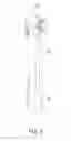
FIG. 1 is a perspective view of a pumping and sucking apparatus according to a first embodiment of the present invention.
FIG. 2 is an exploded view of the pumping and sucking apparatus shown in FIG. 1.
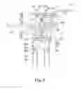
FIG. 3 is a cross-sectional view of the pumping and sucking apparatus shown in FIG. 1.
FIG. 4 is an enlarged partial view of the pumping and sucking apparatus shown in FIG. 3.
FIG. 5 shows the pumping and sucking apparatus in another position than shown in FIG. 4.
FIG. 6 shows the pumping and sucking apparatus in another position than shown in FIG. 5.
FIG. 7 shows the pumping and sucking apparatus in another position than shown in FIG. 6.
FIG. 8 shows the pumping and sucking apparatus in another position than shown in FIG. 7.
FIG. 9 is a perspective view of a pumping and sucking apparatus according to a second embodiment of the present invention.
FIG. 10 is an exploded view of the pumping and sucking apparatus shown in FIG. 9.
FIG. 11 is a cross-sectional view of the pumping and sucking apparatus shown in FIG. 9.
FIG. 12 is an enlarged partial view of the pumping and sucking apparatus shown in FIG. 11.
FIG. 13 shows the pumping and sucking apparatus in another position than shown in FIG. 12.
FIG. 14 shows the pumping and sucking apparatus in another position than shown in FIG. 13.
FIG. 15 shows the pumping and sucking apparatus in another position than shown in FIG. 14.
FIG. 16 shows the pumping and sucking apparatus in another position than shown in FIG. 15.
DETAILED DESCRIPTION OF EMBODIMENTSReferring to FIGS. 1 through 8, there is shown a pumping and sucking apparatus according to a first embodiment of the present invention. The pumping and sucking apparatus includes a cylinder 10, a piston 151 movable in the cylinder 10, a ring 14 for keeping the piston 151 in the cylinder 10, a rod 15 connected to the piston 151, a handle 16 connected to the rod 15, a cap 161 attached to the handle 16, a valve set installed on the cylinder 10 and a lever 13 for pushing the valve set.
Referring to FIGS. 2 and 4, the cylinder 10 defines a chamber 106 for receiving the piston 151 and the rod 15.
The cylinder 10 is formed with head 101 defining a chamber 102, a first aperture 103 in communication with the chamber 102, a second aperture 104 in communication with the chamber 102 and a third aperture 107 for communicating the chamber 102 with the chamber 106.
A first mouth element 11 is positioned in the first aperture 103. A second mouth element 12 is positioned in the second aperture 104. Both of the mouth elements 11 and 12 are made of resilient materials.
The head 101 is formed with a thread around the first aperture 103. The thread of the head 101 can be engaged with a thread of a ring 112 for keeping the first mouth element 11 in the first aperture 103. Formed on the ring 112 is a cap 111 for closing the first mouth element 11.
The valve set includes a housing 20 defines a groove 201 around the periphery, a first channel 211 in communication with the groove 201, an outlet tube defining an outlet 21 in communication with the first channel 211, a second channel 221 in communication with the groove 201 and an inlet tube defining an inlet 22 in communication with the second channel 221. An annular ridge 212 is formed on a shoulder formed between the outlet 21 and the groove 201. A series of separate ridges 222 is formed on a shoulder formed between inlet 22 and the second channel 221. The housing 20 includes a back 26 for contact with the lever 13.
The housing 20 is positioned in the chamber 102 while the outlet tube is inserted in the first aperture 103 and the inlet tube is inserted in the second aperture 104. A least one seal is provided between the periphery of the housing 20 and the wall of the chamber 102. At least one seal is provided between the periphery of the outlet tube and the wall of the first aperture 103. At least one seal is provided between the periphery of the inlet tube and the wall of the second aperture 104. Thus, the groove 201 of the housing 20 is sealed and turned into an air-tight space.
Movably positioned in the outlet 21 is a check valve 231 for contact with the annular ridge 212. A ring 23 is fit in the outlet 21. Formed on the ring 23 is a series of separate ridges 233 toward the check valve 231.
Positioned in the first chamber 103 is a pusher 24 formed with a tip 241 for pushing open a valve installed on an inflatable object. The tip 241 includes a cruciform cross-sectional profile.
Movably positioned in the inlet 22 is a check valve 251 for contact with the separate ridges 222. A ring 25 is fit in the inlet 22. Formed on the ring 25 is an annular ridge 253 toward the check valve 251.
The lever 13 is pivotally connected to the head 101 by a pin 133. The lever 13 is formed with a cam at an end. The cam includes a first face 131 and a second face 132. The first face 131 is closer to the pin 133 than the second face 132 is. Selectively, the first face 131 or the second face 132 is in contact with the back 26 of the housing 20.
Referring to FIGS. 5 and 6, to pump air into the inflatable object, a user inserts the valve of the inflatable object into the first aperture 103, and pivots the lever 13 for bringing the second face 132 of the cam of the lever 13 into contact with the back 26 of the housing 20. The pusher 24 pushes the first mouth element 11 so that the first mouth element 11 fits around the valve of the inflatable object.
Referring to FIG. 5, the piston 151 is moved from the head 101. On one hand, the first check valve 231 is brought into contact with the annular ridge 212, thus sealing the first channel 211 from the outlet 21. On the other hand, the second check valve 251 is removed from the annular ridge 253, thus opening the ring 25. Air is sucked into the cylinder 10 from the exterior.
Referring to FIG. 6, the piston 151 is moved toward the head 101. On one hand, the second check valve 251 is brought into contact with the annular ridge 253, thus sealing the second ring 25. On the other hand, the first check valve 231 is removed from the annular ridge 212, thus bringing the first channel 211 into communication with the outlet 21. Air is pumped into the inflatable object from the cylinder 10.
Referring to FIGS. 7 and 8, to suck air from the inflatable object, the user inserts the valve of the inflatable object into the second aperture 104, and pivots the lever 13 for bringing the second face 132 of the cam of the lever 13 into contact with the back 26 of the housing 20. The second mouth element 12 fits around the valve of the inflatable object.
Referring to FIG. 7, the piston 151 is moved from the head 101. On one hand, the first check valve 231 is brought into contact with the annular ridge 212, thus sealing the first channel 211 from the outlet 21. On the other hand, the second check valve 251 is removed from the annular ridge 253, thus opening the ring 25. Air is sucked into the cylinder 10 from the inflatable object.
Referring to FIG. 8, the piston 151 is moved toward the head 101. On one hand, the second check valve 251 is brought into contact with the annular ridge 253, thus sealing the second ring 25. On the other hand, the first check valve 231 is removed from the annular ridge 212, thus bringing the first channel 211 into communication with the outlet 21. Air is released from the cylinder 10 to the exterior.
Referring to FIGS. 9 through 16, there is shown a pumping and sucking apparatus according to a second embodiment of the present invention. The pumping and sucking apparatus includes a cylinder 30, a piston 351 movable in the cylinder 30, a ring 34 for keeping the piston 351 in the cylinder 30, a rod 35 connected to the piston 351, a handle 36 connected to the rod 35, a cap 361 attached to the handle 36, a valve set installed on the cylinder 30 and a lever 33 for pushing the valve set.
Referring to FIGS. 10 and 12, the cylinder 30 defines a chamber 306 for receiving the piston 351 and the rod 35.
The cylinder 30 is formed with a head 301 defining a chamber 302, a first aperture 303 in communication with the chamber 302, a second aperture 304 in communication with the chamber 302, a third aperture 307 for communicating the chamber 302 with the chamber 306 and a fourth aperture 305 in communication with the chamber 302.
A first mouth element 31 is positioned in the first aperture 303. A second mouth element 32 is positioned in the second aperture 304. Both of the mouth elements 31 and 32 are made of resilient materials.
The head 301 is formed with a thread around the first aperture 303 and another thread around the second aperture 304. The thread around each of the apertures 303 and 304 is engaged with a thread of a ring 312 for keeping a related one of the mouth elements 31 and 32 in the related one of the apertures 303 and 304. Formed on each of the rings 312 is a cap 311 for closing a related one of the mouth elements 31 and 32.
The housing 40 defines an outlet 41, an inlet 42 and a transverse tunnel 46. A first annular shoulder 461 is formed between the transverse tunnel 46 and the outlet 41. The outlet 41 is in communication with the transverse tunnel 46 through an aperture 411 defined by the first annular shoulder 461. A second annular shoulder 462 is formed between the transverse tunnel 46 and the inlet 42. The inlet 42 is in communication with the transverse tunnel 46 through an aperture 421 defined by the second annular shoulder 462. An annular ridge 412 is formed on a side of the first annular shoulder 461. A series of separate ridges 422 is formed on a side of the second annular shoulder 462.
The valve set includes a housing 40 positioned in the head 301. The external diameter of the housing 40 is smaller than the internal diameter of the head 301 so that air can travel between the head 301 and the housing 40. At least two seals are provided between the housing 40 and the head 301 so as to define an air-tight space between the head 301 and the housing 40.
Movably positioned in the outlet 41 is a check valve 431 for contact with the annular ridge 412. A ring 43 is fit in the outlet 41. Formed on the ring 43 is a series of separate ridges 433 toward the check valve 431.
Positioned in the first chamber 303 is a pusher 44 formed with a tip 441 for pushing open a valve installed on an inflatable object. The tip 441 includes a cruciform cross-sectional profile.
Movably positioned in the inlet 42 is a check valve 451 for contact with the separate ridges 422. A ring 45 is fit in the inlet 42. Formed on the ring 45 is an annular ridge 453 toward the check valve 451.
The lever 33 includes a shaft inserted in the transverse tunnel 46 of the housing 40 through the fourth aperture 305 of the head 301. The shaft is positioned by means of a fastener 332. The shaft includes two ends 331 and a cam 333 between the ends 331. At least one seal is provided between each of the ends 331 and the head 301. The cam 333 includes a first face 334, a second face 335 and a lobe 336. The faces 334 and 335 are at an identical distance from the axis of the shaft. The first face 334 is in contact with the first annular shoulder 461, or the second face 335 is in contact with the second annular shoulder 462.
Referring to FIGS. 13 and 14, to pump air into the inflatable object, the user inserts the valve of the inflatable object into the first aperture 303 and pivots the lever 33, thus causing the first face 334 of the cam 333 to contact the first annular shoulder 461 and the lobe 336 to contact the second annular shoulder 462. The pusher 44 pushes the first mouth element 31 so that the first mouth element 31 fits around the valve of the inflatable object.
Referring to FIG. 13, the piston 351 is moved from the head 301. On one hand, the first check valve 431 is brought into contact with the annular ridge 412, thus sealing the aperture 411 from the outlet 41. On the other hand, the second check valve 451 is removed from the annular ridge 453, thus opening the ring 45. Air is sucked into the cylinder 30 from the exterior.
Referring to FIG. 14, the piston 351 is moved toward the head 301. On one hand, the second check valve 451 is brought into contact with the annular ridge 453, thus sealing the second ring 45. On the other hand, the first check valve 431 is removed from the annular ridge 412, thus bringing the aperture 411 into communication with the outlet 41. Air is pumped into the inflatable object from the cylinder 30.
Referring to FIGS. 15 and 16, to suck air from the inflatable object, the user inserts the valve of the inflatable object into the second aperture 304 and pivots the lever 33, thus causing the second face 335 of the cam 333 to contact the second annular shoulder 462 and the lobe 336 to contact the first annular shoulder 461. The second mouth element 32 fits around the valve of the inflatable object.
Referring to FIG. 15, the piston 351 is moved from the head 301. On one hand, the first check valve 431 is brought into contact with the annular ridge 412, thus sealing the aperture 411 from the outlet 41. On the other hand, the second check valve 451 is removed from the annular ridge 453, thus opening the ring 45. Air is sucked into the cylinder 30 from the inflatable object.
Referring to FIG. 16, the piston 351 is moved toward the head 301. On one hand, the second check valve 451 is brought into contact with the annular ridge 453, thus sealing the second ring 45. On the other hand, the first check valve 431 is removed from the annular ridge 412, thus bringing the aperture 411 into communication with the outlet 41. Air is released from the cylinder 30 to the exterior.
The pumping and sucking apparatus of the present invention exhibits the following advantages.
Firstly, the maintenance of the pumping and sucking apparatus is easy since the housing is easily and detachably positioned in the chamber of the head, and the check valves and the rings are easily and detachably positioned in the housing.
Secondly, the operation of the pumping and sucking apparatus is easy since the mouth elements can easily be fit on the valve of the inflatable object without using threads.
The present invention has been described through the description of the embodiments. Those skilled in the art can derive variations from the embodiments without departing from the scope of the present invention. Hence, the embodiments shall not limit the scope of the present invention defined in the claims.
Claims
What is claimed is:1. A pumping and sucking apparatus comprising:
a cylinder defining a space;
a piston movable in the cylinder;
a rod connected to the piston;
a handle connected to the rod;
a head formed on the cylinder, the head defining a space in communication with the space of the cylinder, a first aperture in communication with the space thereof for receiving a valve of an inflatable object in a pumping mode and a second aperture in communication with the space thereof for receiving a valve of an inflatable object in a sucking mode; and
a valve set comprising:
a housing positioned in the chamber defined in the head and formed with an outlet and an inlet;
a first check valve detachably positioned in the outlet for sealing the outlet as the piston is moved from the head and opening the outlet as the piston is moved toward the head; and
a second check valve detachably positioned in the inlet for opening the inlet as the piston is moved from the head and sealing the inlet as the piston is moved toward the head.
2. The pumping and sucking apparatus according to claim 1 comprising a first mouth element positioned in the first aperture of the head for fitting on the valve of the inflatable object and a second mouth element positioned in the second aperture of the head for fitting on the valve of the inflatable object.
3. The pumping and sucking apparatus according to claim 2 comprising a lever installed on the head for causing a selected one of the first and second mouth elements to fit on the valve of the inflatable object, wherein the lever comprises a cam-shaped end in contact with the back of the back of the housing.
4. The pumping and sucking apparatus according to claim 3 wherein the first and second apertures are located on a front of the head while the chamber is located on an opposite side of the head.
5. The pumping and sucking apparatus according to claim 4 wherein the housing comprises a front on which the outlet and inlet are located and a back in contact with the lever.
6. The pumping and sucking apparatus according to claim 3 comprising a pin for pivotally installing the lever on the head.
7. The pumping and sucking apparatus according to claim 6 wherein the cam-shaped end of the lever comprises a first face and a second face further from the pin than the first face is.
8. The pumping and sucking apparatus according to claim 3 wherein the first and second apertures are located on opposite sides of the head.
9. The pumping and sucking apparatus according to claim 8 wherein the housing defines a transverse tunnel, wherein the lever comprises a cam positioned in the transverse tunnel.
10. The pumping and sucking apparatus according to claim 9 wherein the housing comprises a first annular shoulder between the transverse tunnel and the outlet and a second annular shoulder between the transverse tunnel and the inlet, wherein the cam comprises a first face for pushing the first annular shoulder in a pumping mode and a second face for pushing the second annular shoulder in a sucking mode.
11. The pumping and sucking apparatus according to claim 1 wherein the housing defines an annular groove in the periphery for allowing air to travel between the housing and the head, a first channel for communicating the outlet with the annular groove and a second channel for communicating the inlet with the annular groove.
12. The pumping and sucking apparatus according to claim 1 wherein the housing of the valve set is positioned in the head so that there is an air-tight space between them, wherein the housing defines a first channel for communicating the outlet with the air-tight space and a second channel for communicating the inlet with the air-tight space.
13. The pumping and sucking apparatus according to claim 12 wherein the valve set comprises a first ring positioned in the outlet and a second ring positioned in the inlet.
14. The pumping and sucking apparatus according to claim 13 wherein the housing comprises an annular ridge formed on an annular shoulder formed between the first channel and the outlet, wherein the first ring comprises separate ridges formed thereon toward the first check valve.
15. The pumping and sucking apparatus according to claim 13 wherein the housing comprises separate ridges formed on an annular shoulder formed between the second channel and the inlet, wherein the second ring comprises an annular ridge formed thereon toward the second check valve.
16. The pumping and sucking apparatus according to claim 2 comprising a ring installed on the head for retaining one of the mouth elements in a related one of the first and second apertures and a cap connected to the ring for closing the related one of the first and second apertures.
Images & Drawings included:


Sources:
- United States Patent and Trademark Office - verify current appl. status at the USPTO↗
Recent applications in this class:
- » 20240384713 2024-11-21
Portable Air Pump - » 20230417232 2023-12-28
Easy-To-Assemble Floor Pump - » 20220403833 2022-12-22
Bicycle tire pump - » 20220403832 2022-12-22
Inflating device - » 20220333587 2022-10-20
Portable air pump including a piston movable relative to a cylinder provided with an axial member mounted through a third through-hole, and a head seat provided with a fourth through-hole, wherein an axial member is mounted through the third and fourth through-holes - » 20220099075 2022-03-31
Bicycle Tire Pump - » 20210277878 2021-09-09
Inflation pump - » 20210148350 2021-05-20
Portable air pump including a piston movable relative to a cylinder provided with a first through-hole, a pivoting seat provided with a second through-hole, a connection member provided with a third through-hole, and a head seat provided with a fourth through-hole, wherein an axial member is mounted through the first through fourth through-holes - » 20210079903 2021-03-18
Portable Storage Device for Bicycle Tools - » 20200362841 2020-11-19
Bicycle tire pump