Joystick Device With Electric Latching Detents
US20070295147A1
2007-12-27
10/592,595
2005-03-11
Abstract:
A joystick (1) having a yoke pivotally secured to an upper support (28) and a lever (16) pivotally secured to a lower support. The yoke has a latching portion that engages a cam roller (14) on the lever to push the lever downward. Supported on the lever is an armature (24) positioned in spaced relation to a solenoid (26). The solenoid is energized based on the movement of the yoke.
Inventors:
- Stanley N. DIDIER 2 🇺🇸 Plymouth, MN, United States
- Wayne Edmunds 3 🇬🇧 Gwent, United Kingdom
- Terence K. Pontin 1 🇬🇧 Gwent, United Kingdom
Assignee:
- SAUER-DANFOSS INC. 108 🇺🇸 Ames, IA, United States
- Penny & Giles Control Ltd. 1 🇬🇧 Cwmfelinfach, Gwent, United Kingdom
Interested in similar patents?
Get notified when new applications in this technology area are published.
Classification:
G05G5/03 » CPC main
Means for preventing, limiting or returning the movements of parts of a control mechanism, e.g. locking controlling member Means for enhancing the operator's awareness of arrival of the controlling member at a command or datum position; Providing feel, e.g. means for creating a counterforce
B60K37/06 » CPC further
Dashboards; Arrangement of fittings on dashboard of controls, e.g. controls knobs
G05G17/00 » CPC further
Mechanical devices for moving a member after being released; Trip or release mechanisms characterised thereby
B60K2370/126 » CPC further
Details of arrangements or adaptations of instruments specially adapted for vehicles, not covered by groups; Input devices or features thereof; Input devices or input features Rotatable input devices
G05G2009/0477 » CPC further
Manually-actuated control mechanisms provided with one single controlling member co-operating with two or more controlled members, e.g. selectively, simultaneously the controlling member being movable in different independent ways, movement in each individual way actuating one controlled member only in which movement in two or more ways can occur simultaneously the controlling member being movable by hand about orthogonal axes, e.g. joysticks providing feel, e.g. indexing means, means to create counterforce holding the member in a number of definite positions
G05G2700/08 » CPC further
Control mechanisms or elements therefor applying a mechanical movement; Control mechanisms limiting amplitude or adjusting datum position Control mechanisms for locking members in one or more positions
Y10T74/20582 » CPC further
Machine element or mechanism; Control lever and linkage systems; Elements Levers
Y10T74/20636 » CPC further
Machine element or mechanism; Control lever and linkage systems; Elements Detents
G05G5/06 » CPC further
Means for preventing, limiting or returning the movements of parts of a control mechanism, e.g. locking controlling member for holding members in one or a limited number of definite positions only
G05G19/00 » CPC further
Servo-mechanisms with follow-up action, e.g. occurring in steps
Description
CROSS REFERENCE TO RELATED APPLICATIONSThis application claims the benefit of U.S. Provisional Application No. 60/552,468, filed Mar. 12, 2004.
BACKGROUND OF THE INVENTIONMachine operators of off-road equipment such as tractors and loaders have come to expect certain functionality in the heavy machinery, particularly the operation of attachments and various work functions. For example, the operator of a backhoe loader controls the position of the bucket by affecting the position of a control lever or joystick. Conventional control levers consist of a hydraulic valve that an operator manipulates, causing various actuators to affect the position of the bucket. Certain positions of the control lever will cause the machine to place the bucket in corresponding positions.
The position at the end of the control lever's travel often is referred to as the detent position. The control lever generally stays in the detent position until the bucket has reached its corresponding position, at which point the control lever returns to its at-rest position. Conventional control levers included an integrated hydraulic valve, whereby the hydraulic flow forces in the valve accomplished the task of returning the control lever to the at-rest position. More recently, joystick devices have incorporated electronic solenoid valves to electro-magnetically “latch” the joystick into the detent position. In this arrangement, an electronic signal from a sensor or a micro controller is used to release the solenoid and return the joystick to the at-rest position.
Conventional control levers and joysticks still rely upon an integrated hydraulic valve, though, to ultimately affect the position of the bucket or other heavy machinery attachment. It is therefore a primary object of this invention to create a joystick that uses electronic sensors and not hydraulic valves for controlling heavy machinery.
SUMMARY OF THE INVENTIONA joystick device having an upper support and a lower support having a yoke pivotally secured to the upper support and a lever pivotally secured to a lower support. The yoke has at least one latching portion that engages a cam roller on the lever to move the lever downward. The lever is normally maintained in an upward position by a spring. An armature is supported by the lever and is in parallel spaced relation to a solenoid. A micro controller senses the movement of the yoke and energizes the solenoid.
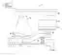
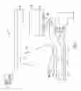
BRIEF DESCRIPTION OF THE DRAWINGSFIG. 1 is a side view of the joystick of the present invention.
DETAILED DESCRIPTION OF THE INVENTIONThe joystick 1 uses a gimble-type mechanism, whereby the joystick movement is created and controlled by a pair of yokes mounted at 90° with respect to one another. In this arrangement, one of the yokes pivots about its main axis and swings through an arc when the joystick is moved in a forward or reverse direction (Y-axis), and the other yoke pivots about its main axis and swings through an arc when the joystick is moved in a left or right direction (X-axis). The joystick is equipped with electronic sensors that measure the position of the yokes to provide the desired electrical proportional signal. A micro controller 2 in the joystick processes this signal for use by the machine, valve, or other main controller. The micro controller also may process the signal for solenoid actuation, as discussed below. A main spring, not shown, provides the means for returning the joystick and yokes to an at-rest position, which is a neutral position where the yokes are essentially centered between the forward/reverse and left/right positions.
As shown in FIG. 1, a yoke 10 is provided with a yoke cam profile 12. A cam roller 14 rides along the yoke cam profile as the joystick is moved from the at-rest position to a full travel position. This cam profile 12 may be tailored to give the desired operating feel depending upon the application. The yoke cam 12 profile also may be tailored to give different operating features for the forward (+) and the reverse (−) movement of the joystick.
The cam roller 14 is supported by a lever 16. The lever 16 pivots about the lower support 18 and is held against the cam roller 14 and yoke cam profile 12 by a spring 20. The spring 20 is preloaded to overcome the effects of gravity and vibration, thereby ensuring that the cam roller 14 is always in contact with the yoke 10.
An alignment mechanism 22 is attached to the lever 16 and supports the armature 24. The alignment mechanism 22 maintains the armature 24 and solenoid 26 in parallel spaced relation to one another for proper operation and coupling. The pole piece, or main body of the solenoid 26, is attached to the upper support 28 of the joystick 1. When the solenoid 26 is energized, the armature 24 becomes magnetically coupled to the pole piece, which prevents the lever from pivoting. Depending on the cam profile 12 and the position of the yoke 10, preventing the lever from pivoting holds the joystick in the detented position.
In operation, the operator manipulates the joystick, thereby causing one of the yokes 10 to pivot. In the at-rest position, the solenoid 26 is not energized. As the cam roller 14 engages with the latch 30 on the yoke cam profile 12, the cam roller 14 forces the lever 16 downward and compresses the spring 20. The micro controller will sense that the position of the yoke 10 is nearing the detent position and will energize the solenoid 26. Because the lever is down, however, the armature 24 and the main body of the solenoid 26 will not couple. As the operator continues to manipulate the joystick, the cam roller 14 moves past the latch 30 on the yoke cam profile 12 and the spring 20 returns the lever 16 to its upward position. Continued movement will cause the armature 24 and the solenoid 26 to come in close enough proximity to each other so that the coupling occurs, latching the joystick in the detent position.
Once in the detent position, the operator may release the joystick 1 by exerting force to pull the joystick out of the detent. The joystick also may be electrically removed from the detent by de-energizing the solenoid 26. The loss of the electrical signal to the solenoid 26 will cause the magnetic coupling to cease, and the main spring (not shown) in the joystick has sufficient force to return the joystick to the at-rest state.
Claims
What is claimed is:1. A joystick device having an upper support and a lower support comprising: a yoke pivotally secured to the upper support and having at least one latching portion; a lever pivotally secured to the lower support and being maintained in an upward position by a spring; a solenoid armature supported by the lever and in parallel spaced relation with a solenoid; a cam roller in engagement with both the yoke and the lever wherein the latching portion causes the cam roller to move the lever downward; and a micro controller that senses the movement of the yoke and energizes the solenoid.
2. The device of claim 1 wherein an alignment mechanism is attached to the armature.
Images & Drawings included:
Sources:
- United States Patent and Trademark Office - verify current appl. status at the USPTO↗
Recent applications in this class:
- » 20250165024 2025-05-22
PEDAL DEVICE - » 20250155914 2025-05-15
PEDAL ASSEMBLY - » 20250076916 2025-03-06
OPERATION DEVICE - » 20250036155 2025-01-30
PEDAL SIMULATOR - » 20250028347 2025-01-23
OPERATING APPARATUS - » 20250028346 2025-01-23
PEDAL DEVICE - » 20250021125 2025-01-16
MULTI-SPRING BRAKE EMULATOR - » 20240419203 2024-12-19
ROTATING LOAD DEVICE USING MAGNETO-RHEOLOGICAL FLUID AND CONTROL METHOD THEREFOR - » 20240393821 2024-11-28
TRIGGER MODULE WITH FORCE FEEDBACK - » 20240345615 2024-10-17
PEDAL SIMULATOR
Recent applications for this Assignee:
- » 20150066297 2015-03-05
Multi-sonic sensor - » 20150054279 2015-02-26
SYSTEM FOR A HYDRAULICALLY POWERED ELECTRIC GENERATOR - » 20150053028 2015-02-26
Bearing assembly for isolating and damping swashplate vibration - » 20130213214 2013-08-22
Swashplate pivot bearing - » 20130180100 2013-07-18
Method of actuating a wireless sensor of road construction equipment - » 20130174723 2013-07-11
Neutral setting apparatus of an adjustable hydraulic machine - » 20130158812 2013-06-20
Sensing system for road construction equipment - » 20130124030 2013-05-16
SENSING SYSTEM FOR AN AUTOMATED VEHICLE - » 20130124010 2013-05-16
Sensing system for an automated vehicle - » 20130121764 2013-05-16
Sensor system for construction equipment having wireless sonic sensor system