Configuration for accommodating, transferring and/or transporting at least one functional part of a technical device
US20080014072A1
2008-01-17
11/825,421
2007-07-06
Abstract:
A configuration for accommodating and transferring and/or transporting at least one functional part, in particular a tool of a technical device such as a device for automatically sealing containers, has at least one chassis, which supports the functional part accommodating device. There is at least one stop element for the chassis, which is disposed on the technical device. There is at least one gripper element disposed on the chassis, which can be brought into engagement with the stop element.
Interested in similar patents?
Get notified when new applications in this technology area are published.
Classification:
B62B3/002 » CPC main
Hand carts having more than one axis carrying transport wheels; Steering devices therefor; Equipment therefor characterised by a rectangular shape, involving sidewalls or racks
B62B3/0643 » CPC further
Hand carts having more than one axis carrying transport wheels; Steering devices therefor; Equipment therefor involving means for grappling or securing in place objects to be carried; Loading or unloading equipment for simply clearing the load from the ground the wheels remaining stationary while the supporting surface is lifted
B29C65/02 » CPC further
Joining of preformed parts ; Apparatus therefor by heating, with or without pressure
B29C66/53461 » CPC further
General aspects of processes or apparatus for joining preformed parts; General aspects of joining tubular articles; General aspects of joining long products, i.e. bars or profiled elements; General aspects of joining single elements to tubular articles, hollow articles or bars; General aspects of joining several hollow-preforms to form hollow or tubular articles; Joining tubular articles, profiled elements or bars; Joining single elements to tubular articles, hollow articles or bars; Joining several hollow-preforms to form hollow or tubular articles; Joining single elements to tubular articles, hollow articles or bars; Joining single elements to open ends of tubular or hollow articles or to the ends of bars said single elements being substantially flat joining substantially flat covers and/or substantially flat bottoms to open ends of container bodies
B29C66/8167 » CPC further
General aspects of processes or apparatus for joining preformed parts; General aspects of machine operations or constructions and parts thereof; General aspects of the pressing elements, i.e. the elements applying pressure on the parts to be joined in the area to be joined, e.g. the welding jaws or clamps characterised by the mounting of the pressing elements, e.g. of the welding jaws or clamps Quick change joining tools or surfaces
B29C66/8322 » CPC further
General aspects of processes or apparatus for joining preformed parts; General aspects of machine operations or constructions and parts thereof characterised by the movement of the joining or pressing tools; Reciprocating joining or pressing tools Joining or pressing tools reciprocating along one axis
B29C66/841 » CPC further
General aspects of processes or apparatus for joining preformed parts; General aspects of machine operations or constructions and parts thereof; Specific machine types or machines suitable for specific applications Machines or tools adaptable for making articles of different dimensions or shapes or for making joints of different dimensions
B29C66/8432 » CPC further
General aspects of processes or apparatus for joining preformed parts; General aspects of machine operations or constructions and parts thereof; Specific machine types or machines suitable for specific applications; Machines for making separate joints at the same time in different planes; Machines for making separate joints at the same time mounted in parallel or in series Machines for making separate joints at the same time mounted in parallel or in series
B29L2031/712 » CPC further
Other particular articles Containers; Packaging elements or accessories, Packages
B62B2203/10 » CPC further
Grasping, holding, supporting the objects comprising lifting means
B65B51/00 IPC
Devices for, or methods of, sealing or securing package folds or closures; Devices for gathering or twisting wrappers, or necks of bags
Description
BACKGROUND OF THE INVENTION
1. Field of the Invention
The invention relates to a configuration for accommodating and transferring and/or transporting at least one functional part, in particular a tool of a technical device such as a device for automatically sealing containers, comprising at least one chassis, which supports the functional part accommodating device.
2. The Prior Art
Technical devices encompass different functional parts. If a technical device is a device for automatically sealing containers, this device encompasses at least one tool for sealing the container. This tool is, for example, a foil welding apparatus, which can be divided into a lower tool and an upper tool. Containers which are to be sealed are guided against the upper tool by the lower tool, wherein a foil for sealing the containers is disposed between the containers and the upper tool.
The use of different tools may be required for different containers. On the one hand, the lower tool is adapted to the shape of the container and, on the other hand, different numbers of containers can be sealed in one operating step by means of the lower tool and the upper tool.
For the thus necessary replacement of the tools of a device, German Patent No. DE 102 09 000.9 proposes a chassis, with which a tool can be accommodated, transferred and transported to a technical device. This chassis encompasses sections, which can be attached to a lower side of a technical device.
This known chassis cannot simply be used in a technical device, which, in its bottom region, does not encompass a free space for attaching such sections.
SUMMARY OF THE INVENTION
It is therefore an object of the invention to provide a configuration of the above-mentioned species, which enables a transfer of functional parts to a chassis and vice versa universally for a variety of technical devices.
According to the invention, this object is solved in that the configuration comprises at least one stop element for the chassis, which is disposed on the technical device, There is at least one gripper element disposed on the chassis, which can be brought into engagement with the stop element.
In the configuration according to the invention, measures are provided on the technical device itself, as well as on a chassis. Both components are equipped with means, which enable a close attachment of the chassis to the technical device.
For this purpose, the stop element is disposed on the technical device. The chassis encompasses a gripper element, which can be brought into engagement with the stop element. A firmly positioned allocation of the chassis to the technical device is thus made possible.
The connection between the technical device and the chassis thus takes place above a base of the technical device, i.e., where the stop elements are disposed on the technical device. These stop elements can be disposed on technical devices, which are very different from one another, so that a universal allocation of the chassis to the technical devices is made possible. For this position allocation to remain over a longer period as well, e.g. for the transfer or take-over of a tool in a stable manner, at least one bearing element, which, when the gripper element is engaged with the technical device so as to abut in a defined manner, is disposed on the chassis in a first embodiment of the invention. This bearing element is attached to the technical device, but must not be attached to the lower side of the technical device. The attachment on the technical device only serves for maintaining a reliable resting position if the gripper element is engaged with the stop element.
The stop elements are designed, for example, as protrusions, while the gripper elements contain the protrusions. The containment of protrusions by the gripper elements enables a close connection. Nonetheless, the connection can thereby be carried out rapidly so as not to delay the delivery and removal, respectively, of functional parts to the technical device and away from the technical device, respectively. Each protrusion can be a bolt.
According to an embodiment of the invention, each gripper element is a mounting eyelet, in particular for the purpose of accelerating the configuration of the gripper element on the protrusions. This mounting eyelet can be attached to a bolt in a simple manner in that it is simply hooked in.
Preferably, the stop elements for the chassis are disposed in an upper region of the technical device. The gripper elements are then arranged in the same manner in an upper section of a chassis, so that the gripping of the stop elements occurs in the upper region of the chassis by the gripper elements. The chassis is thereby virtually hung up in the upper region on the gripper elements; it is pushed against the technical device with its center of gravity, which is arranged lower.
In this region where the chassis is attached on the technical device, the bearing element is initially preferably disposed. Preferably, the bearing element is designed as a bearing surface, which can be guided against a corresponding countersurface of a technical device in a simple manner and on which it can be attached. The bearing element is thereby disposed in a lower region of the chassis so that it is accordingly located below the gripper elements.
For a further embodiment of the invention, the chassis has wheels that are accommodated on the chassis so as to be adjustable in height. The wheels thus ensure that the chassis can be moved. The height adjustability of the wheels enables an adaptation of the chassis to different technical devices comprising stop elements disposed in different elevations.
Preferably, the front and rear wheels of the chassis are combined in groups having a common activation of their height adjustability, in each case in the direction of approximation on the technical device. According to this development, the height adjustment moves the two front wheels together and the two rear wheels together. This separation of the height adjustability can then be used in a simplified approximation on the technical device. Front sections of the chassis can thus be slightly tilted forward due to a greater height adjustment of the rear wheels. If the gripper elements are disposed in these front sections, they are guided slightly to the front so as to simplify an encompassing of the plug-in element. Subsequently, the rear wheels can then again be adjusted lower and all of the wheels can be adjusted to be so low that the bearing element of the chassis is attached on the technical device.
Each wheel is thereby preferably designed as a guide roller having a rotatability of 360°.
BRIEF DESCRIPTION OF THE DRAWINGS
Other objects and features of the present invention will become apparent from the following detailed description considered in connection with the accompanying drawings. It is to be understood, however, that the drawings are designed as an illustration only and not as a definition of the limits of the invention.
In the drawings, wherein similar reference characters denote similar elements throughout the several views:
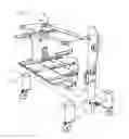
FIG. 1 shows a perspective view of a chassis comprising a functional part accommodating device according to one embodiment of the invention;
FIG. 2 shows a perspective view of a device for automatically sealing containers;
FIG. 3 shows an enlarged view of the detail III in FIG. 2; and
FIG. 4 shows a perspective view of the technical device according to FIG. 2 and of the chassis according to FIG. 1 in the event that the chassis is attached on the technical device.
DETAILED DESCRIPTION OF THE PREFERRED EMBODIMENT
Referring now in detail to the drawing, the chassis in FIG. 1 is a part of the configuration according to the invention. The chassis encompasses a framework 1 consisting of profiles. This framework 1 supports a functional part accommodating device 2, with which a sealing tool of the technical device according to FIG. 2 can be accommodated, for example.
Two mounting eyelets 4 are disposed on the chassis on side walls 3 of the framework 1. Both mounting eyelets 4 are connected with one another by means of a rod profile 5, so as to stabilize the defined distance between both mounting eyelets 4.
Framework 1 of the chassis stands on four wheels 6. Each wheel 6 is held in a telescopic cylinder so as to be adjustable in height, said telescopic cylinder being disposed in a telescopic cylinder accommodation 7. The height configuration of framework 2 above a non-illustrated base changes by retracting and extending of wheels 6, which can be rotated by 360°, respectively.
Likewise, the technical device in FIG. 2 encompasses a frame 8. Frame 8 supports the functional parts of the technical device, inter alia an upper tool 9 and a lower tool 10. These tools 9, 10 serve for sealing bowls, e.g. Lower tool 10 shows that this tool 10 is suitable for accommodating three bowls in a sealing process. If other bowls are to be sealed, lower tool 10 and, if applicable, upper tool 9 are to be removed from the technical device and replaced, in each case, by another tool.
For an approximation of the chassis according to FIG. 1, the technical device in FIG. 2 is equipped with bolts 11, which are also illustrated in FIG. 3. Bolts 11 protrude from an adjacent wall 12 of the technical device so that they form a possibility for engagement for mounting eyelets 4.
FIG. 4 shows the mounted state of the chassis on the technical device. The mounting eyelets 4 are engaged with the bolts 11. The framework 1 is attached on the technical device with front telescopic cylinder accommodations 7. In the technical device, this attachment occurs on frame 8. In the chassis, provision is made for bearing surfaces 13 on the front side of the front telescopic cylinder accommodation 7. These bearing surfaces 13 are designed, e.g., by the front edges of cover elements 14, which close the telescopic cylinder accommodations 7 at the top.
Accordingly, while only a few embodiments of the present invention have been shown and described, it is obvious that many changes and modifications may be made thereunto without departing from the spirit and scope of the invention.
Claims
What is claimed is:1. A configuration for accommodating and transferring or transporting at least one functional part of a technical device, the configuration comprising:
at least one chassis, which supports a functional part accommodating device;
at least one stop element for the chassis being disposed on the technical device;
at least one gripper element, which can be brought into engagement with the stop element, said gripper element being disposed on the chassis.
2. The configuration according to claim 1, further comprising at least one bearing element disposed on the chassis for engaging the gripper element the technical device so as to be attached in a defined manner.
3. The configuration according to claim 1, wherein the stop elements are designed as protrusions and the gripper elements engage the protrusions.
4. The configuration according to claim 3, wherein each protrusion is a bolt.
5. The configuration according to claim 3, wherein each gripper element is a mounting eyelet.
6. The configuration according to claim 1, wherein the gripper element is disposed in an upper section of the chassis.
7. The configuration according to claim 2, wherein the bearing element of the chassis is a bearing surface.
8. The configuration according to claim 2, wherein the bearing element is disposed in a lower region of the chassis.
9. The configuration according to claim 1, wherein the chassis has wheels that are adjustable in height.
10. The configuration according to claim 9, wherein the wheels disposed at a front section of the chassis and the wheels disposed at a rear section of the chassis are each combined in groups having a common activation of their height adjustability, in a direction of approximation on the technical device.
11. The configuration according to claim 9, wherein each wheel is designed as a guide roller having a rotatability of 360°.
Images & Drawings included:


Sources:
- United States Patent and Trademark Office - verify current appl. status at the USPTO↗
Recent applications in this class:
- » 20250058809 2025-02-20
Pallet Mobilizer System and Method - » 20240227892 2024-07-11
SINGLE-OPERATOR MULTI-FUNCTION FOLDABLE TRANSPORTER - » 20240199104 2024-06-20
Shopping Trolley - » 20230406380 2023-12-21
HOUSING STRUCTURE AND OBJECT USING THE SAME - » 20230399039 2023-12-14
Double-decker industrial cart - » 20230249729 2023-08-10
Cart/tray apparatus and system - » 20230182795 2023-06-15
OUTDOOR MOBILE OFFICE POD - » 20220315080 2022-10-06
Cart device - » 20210046963 2021-02-18
Foldable beach wagon - » 20210009177 2021-01-14
MULTI-TIERED SLEEVE PACK ASSEMBLY