Swivel recoiler
US20080035778A1
2008-02-14
11/503,684
2006-08-14
Abstract:
A recoiler has a retractable cable with an attachment pad on the distal end of the cable for attachment to an item of merchandise. The cable is stored on a spring biased spool located within a recoiler housing. The housing is freely rotatably mounted on a post extending upwardly from a base plate secured to the spool housing by a fastener and adapted to be secured to a support structure.
Inventors:
- James K. Sankey 24 🇺🇸 Charlotte, NC, United States
- Dennis D. Belden 23 🇺🇸 Canton, OH, United States
Assignee:
- Alpha Security Products, Inc. 61 🇺🇸 Charlotte, NC, United States
Interested in similar patents?
Get notified when new applications in this technology area are published.
Classification:
B65H75/446 » CPC main
Storing webs, tapes, or filamentary material, e.g. on reels; Cores, formers, supports, or holders for coiled, wound, or folded material, e.g. reels, spindles, bobbins, cop tubes, cans, mandrels or chucks specially adapted or mounted for storing and repeatedly paying-out and re-storing lengths of material provided for particular purposes, e.g. anchored hoses, power cables involving the use of a core or former internal to, and supporting, a stored package of material; Constructional details; Arrangements of the frame or housing for releasably or permanently attaching the frame to a wall, on a floor or on a post or the like
A45F5/004 » CPC further
Holders or carriers for hand articles; Holders or carriers for use while travelling or camping with an automatic spring reel
A47F7/024 » CPC further
Show stands, hangers, or shelves, adapted for particular articles or materials for jewellery, dentures, watches, eye-glasses, lenses, or the like with provisions for preventing unauthorised removal
B65H75/48 IPC
Storing webs, tapes, or filamentary material, e.g. on reels; Cores, formers, supports, or holders for coiled, wound, or folded material, e.g. reels, spindles, bobbins, cop tubes, cans, mandrels or chucks specially adapted or mounted for storing and repeatedly paying-out and re-storing lengths of material provided for particular purposes, e.g. anchored hoses, power cables involving the use of a core or former internal to, and supporting, a stored package of material; Constructional details Automatic re-storing devices
Description
BACKGROUND OF THE INVENTION
1. Technical Field
The invention relates to a recoiler having a retractable cable which is adapted to be connected to an item of merchandise to enable a customer to inspect the merchandise while retaining the merchandise in a secure position. More particularly, the invention relates to such a recoiler in which the recoiler mechanism is contained within a housing which is mounted on a swivel enabling it to rotate so that the cable extends at the correct angle at all times from the recoiler to the merchandise connected thereto.
2. Background Information
Numerous types of recoilers have been developed which include a cable that is extendable out of the recoiler and attached to an item of merchandise to enable a potential customer to inspect and handle the merchandise conveniently, yet prevent the merchandise from leaving a display counter. These recoilers have some type of spring mechanism which is contained in the recoiler to exert a biasing force on the cable or be provided with various indexing mechanisms to retain the cable in an extended position without exerting a retraction force on the merchandise. Many of these prior art recoilers have an alarm system associated therewith which will sound an alarm if the merchandise connecting cable is cut or the merchandise removed from the cable.
Although these prior art recoilers work satisfactorily for their intended purpose, one problem is that the customer, when handling the merchandise, occasionally will put an undesirable force on the cable in an angled direction with respect to the recoiler housing possibly damaging the housing. Furthermore, these prior recoilers can restrict the movement of the protected merchandise making it more difficult for the customer to adequately review and manipulate the merchandise prior to purchasing the same. Also, these prior art recoilers, once attached to a supporting structure by some mechanism, have an optimal position in which the cable is pulled out of and retracted into the housing so as to enter at a desired angle and if deviated therefrom puts undesirable unbalanced forces on the recoiler.
Therefore, the need exists for an improved recoiler which is mounted in a secure position on a support structure and connected to an item of merchandise and in which the recoiler is freely rotatably moveable on its supporting base thereby ensuring that the cable will always extend and retract in the desired direction from and back into the internal spool located within the recoiler housing.
BRIEF SUMMARY OF THE INVENTION
One aspect of the present invention is to provide a recoiler in which the housing contains a spool for storing and paying out a length of cable, the distal end of which is connected by an attachment pad or other device to an item of merchandise, wherein the housing is mounted on a swivel base ensuring that the cable is always pulled from the housing and retracted back into the housing at the most efficient angle to prevent unbalanced forces acting upon the cable spool rotatably mounted within the recoiler housing.
A further aspect of the present invention is to provide a relatively simple and inexpensive recoiler which is mounted on a swivel base, wherein the recoiler is formed of several one-piece members of inexpensive rigid plastic material, which members when assembled together prevent unauthorized access to the interior of the recoiler, and which once placed on a supporting structure will always have the proper orientation for attaching the cable to an item of merchandise.
Still another feature of the present invention is to provide a mounting base which provides the swivel for the recoiler housing with a pressure sensitive adhesive pad enabling the recoiler to be mounted and retained on a support structure with a second attachment pad being located at a distal end of the cable also having a pressure sensitive adhesive pad for ease of attachment to an item of merchandise to be restrained by the spring biased cable.
A further aspect of the present invention is to provide a constant spring bias force on the cable for retracting the cable into the recoiler housing thereby eliminating expensive ratchet and stop mechanisms heretofore used in prior art recoilers to prevent undesirable forces acting on the internal spool, since the cable of the present invention will always extend from the housing in the optimum direction due to the swivel mounting of the recoiler housing on the swivel base.
These features and advantages of the present invention are obtained by the recoiler of the present invention comprising a housing containing a spool, a length of cable stored on the spool, and a spring biasing the spool and cable in a retractable direction; a base having an upstanding post pivotally mounting the housing on the base; and an attachment member for attaching the base on a supporting structure.
BRIEF DESCRIPTION OF THE SEVERAL VIEWS OF THE DRAWINGS
A preferred embodiment of the invention, illustrated of the best mode in which Applicant contemplates applying the principles, is set forth in the following description and is shown in the drawings and is particularly and distinctly pointed out and set forth in the appended claims.
FIG. 1 is a diagrammatic side elevation of the swivel recoiler of the present invention mounted on a supporting structure and connected to an item of merchandise.
FIG. 2 is a top plan view of the swivel recoiler connected as shown in FIG. 1 with the swivel feature being shown by the alternate dot dashed positions of the merchandise.
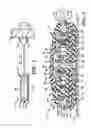
FIG. 3 is an exploded perspective view of the swivel recoiler of the present invention.
FIG. 4 is an enlarged sectional view taken on line 44, FIG. 2.
Similar numbers refer to similar parts throughout the drawings.
DETAILED DESCRIPTION OF THE INVENTION
The recoiler of the present invention is indicated generally at 1, and is shown in FIGS. 1 and 2 being connected to an item of merchandise 3. Merchandise 3 is depicted as being a camera. However any item of merchandise and other types of objects can be connected to the recoiler by an attachment pad 5, which is connected to the distal end of a cable 7. Attachment pad 5 can be connected easily to merchandise 3 by a disc-shaped pressure sensitive adhesive pad 9 or other type of attachment device. Recoiler 1 preferably is mounted on a support structure 11 by a second pressure sensitive adhesive pad 13 or other type of mechanism.
The components of recoiler 1 are best shown in FIGS. 3 and 4. Recoiler 1 includes a housing indicated generally at 15, which includes a bottom housing member 17 and a top housing member 19, each of which preferably is formed as a one piece member of plastic material enabling them to be mass produced at a relatively low cost. A spool 21 stores a predetermined length of cable 7 which extends outwardly through a cable outlet opening 25 formed by aligned notches 26 and 27 provided in bottom housing member 17 and top housing member 19, respectively. Preferably a cable guide 29 is located in outlet opening 25 to facilitate the movement of the cable in and out of the outlet opening by reducing the sliding friction between the cable and housing.
Bottom housing member 17 is of an annular configuration having a cylindrical side wall 31 and a disk-shaped bottom 33. An annular spindle 35 is formed integrally with bottom 33 and extends upwardly therefrom and has an annular slot 37 formed therein for slidably receiving and retaining a tab 39 provided on one end of a coil spring 41. Spool 21 has a pair of spaced annular flanges 21A and 21B which forms a cable storage chamber 21C therebetween. Spool 21 is formed with an annular central recess 43 and a central opening 45 and has a small slot 49 is formed in an inner edge of flange 21A for receiving a coil spring attachment tab 50 therein. A arcuate slot 51 terminates in an enlarged end opening 52 for receiving cable 7 therethrough and for securing the cable to spool 21 by a ferrule 54 connected to the inner end of the cable.
Top housing member 19 preferably has a dome-shaped top 57 with a central recess 59 and a center hole 61 for receiving a fastener 63 therethrough as discussed below. A cover 65 complementary in shape to the diameter of recess 59, is snap-fitted or permanently secured in the recess after the recoiler has been assembled to provide a pleasing appearance thereto and prevent access to fastener 63. Housing members 17 and 19 are permanently secured together such as with a sonic weld, an adhesive or other type of securement means to provide a secure internal chamber for rotatably mounting spool 21 therein. When in the assembled position as shown in FIG. 4, spool 21 is rotatably mounted on spindle 35 which extends through spool opening 45, with coil spring tab 39 being connected to spindle 35 in slot 37 and outer coil spring tab 50 being connected in slot 49 of spool 21. Cable 7 is connected at its inner end by ferrule 54 to spool 21 with its distal end being connected to attachment pad 5, which may include an end cap 67 on which pressure sensitive adhesive pad 9 is secured.
In accordance with the main feature of the invention, recoiler housing 15 is rotatably mounted on a swivel base indicated generally at 70. Base 70 preferably is a one piece member formed of plastic and has a disc-shaped base 71 with an annular post 73 extending upwardly therefrom having a hollow interior 75 and an annular boss 76 at the base of post 73. Double-sided pressure sensitive pad 13 preferably is attached to the bottom surface 78 of swivel base 71 for securing it to the top of support structure 11 as shown in FIG. 4. As shown in FIG. 4, housing 15 is rotatably mounted on swivel 70 by bottom housing member 17 resting upon the top surface of annular boss 76 with post 73 extending upwardly through hollow interior 36 of spindle 35. Fastener 63 is threadably engaged in bore 75 of post 73 with an enlarged head 68 of fastener 63 trapping housing 15 thereon. Thus, as shown in FIG. 4, housing 15 is freely rotatably mounted on post 73 with very little rotational frictional engagement occurring between a small portion of bottom housing member 17 and the top surface of boss 76. Thus, no matter which direction cable 7 is pulled outwardly from housing 15, the housing will rotate in the desired direction as shown by the two alternate dot dashed positions in FIG. 2. This avoids cable 7 putting an undesirable force on spool 21 and the internal mechanism thereof. As the cable is pulled outwardly, spool 21 rotates with respect to spindle 35 tensioning coil spring 41 so that when the outward pressure on cable 7 indicated by Arrow head A in FIG. 1 is released, coil spring 41 will bias cable 7 in the direction of Arrow head B retracting the attached article of merchandise to a desired storage position.
Thus, recoiler 1 provides an extremely simple recoiler mechanism which includes a swivel whereby the cable is always pulled from the recoiler housing and the internal spool in the desired direction for attachment to an item of merchandise or other object, and in which the spring will automatically bias the cable toward a retracted position onto the spool when the extraction pressure is released therefrom. Housing 15 will always rotate or swivel easily on swivel post 73 to ensure that the correct alignment is maintained between the housing and item of merchandise.
In the foregoing description, certain terms have been used for brevity, clearness, and understanding. No unnecessary limitations are to be implied therefrom beyond the requirement of the prior art because such terms are used for descriptive purposes and are intended to be broadly construed.
Moreover, the description and illustration of the invention is an example and the invention is not limited to the exact details shown or described.
Claims
1. A recoiler for automatically retracting a cable comprising:
a housing containing a spool, a length of cable stored on said spool, and a spring biasing the spool and cable in a retractable direction;
a base having an upstanding post pivotally mounting the housing on said base; and
an attachment member for attaching the base on a supporting structure.
2. The recoiler defined in claim 1 wherein the housing includes top and bottom members secured together and forming an internal chamber; in which a spindle extends outwardly from the bottom housing member into the chamber and rotatably mounts the spool thereon; and in which the spring is a coil spring having one end attached to the bottom housing spindle and another end attached to the spool.
3. The recoiler defined in claim 2 wherein the spool includes a central recess with a central opening through which the spindle extends; and in which the coil spring is located within the central recess and extends about the spindle.
4. The recoiler defined in claim 2 wherein the base post extends into a hollow interior of the spindle for rotatably mounting the housing on the post.
5. The recoiler defined in claim 4 wherein the base post includes a boss; and in which the bottom housing member is rotatably supported on the boss.
6. The recoiler defined in claim 5 wherein the base is a one-piece member formed of plastic.
7. The recoiler defined in claim 4 wherein the base post extends through an opening formed in the top housing member; and in which a fastener having an enlarged head is secured in the base post to secure the housing on said base post.
8. The recoiler defined in claim 7 wherein the top housing member includes a top central recess; in which the fastener head is located in said central recess; and in which a cover is mounted on the top housing member concealing the fastener head.
9. The recoiler defined in claim 2 in which each of the top and bottom housing members is a one-piece member formed of plastic.
10. The recoiler defined in claim 1 wherein the attachment member is a pad having opposed surfaces, one surface being attached to a bottom surface of the base and having a pressure sensitive adhesive on the other surface for securing the base to the supporting structure.
11. The recoiler defined in claim 1 wherein one end of the cable is attached to the spool and an opposite end is secured to an attachment pad; and in which the attachment pad has a member for attaching the pad to an item of merchandise.
12. The recoiler defined in claim 11 wherein the attachment pad member is a disc of pressure sensitive adhesive.
Images & Drawings included:


Sources:
- United States Patent and Trademark Office - verify current appl. status at the USPTO↗
Similar patent applications:
Recent applications in this class:
- » 20240343524 2024-10-17
Mounting brackets for cord reels - » 20240286867 2024-08-29
VEHICLE HOOK CAPABLE OF PREVENTING REEL DISENGAGEMENT AND VEHICLE - » 20240101389 2024-03-28
CORD REEL HOLDER - » 20230069667 2023-03-02
Countertop barrier device - » 20220081250 2022-03-17
Outdoor hose storage enclosure - » 20200031610 2020-01-30
ELECTRICAL EXTENSION CORD ORGANIZER AND STORAGE DEVICE - » 20180319620 2018-11-08
String Dispensing Assembly For Use In Connection With Ceiling Installation - » 20150246789 2015-09-03
HOSE REEL ASSEMBLY - » 20140077021 2014-03-20
Retractor safety device - » 20110240360 2011-10-06
CONCEALED-TYPE RETRACTABLE EXTENSION CORD ORGANIZING STRUCTURE
Recent applications for this Assignee:
- » 20090057244 2009-03-05
Merchandise display with time delay mechanism - » 20080197246 2008-08-21
Adapter for article display stand - » 20080174430 2008-07-24
Alarm systems, remote communication devices, and article security methods - » 20080169924 2008-07-17
Banding clip alarm - » 20080156959 2008-07-03
Magnetic shielding for display device - » 20080146069 2008-06-19
Cable attachment device - » 20080142665 2008-06-19
Adjustable display assembly for a retail product - » 20080061975 2008-03-13
Portable alarming security device - » 20080030334 2008-02-07
Bottle security device - » 20080030333 2008-02-07
Bottle security device