Buck converter fault detection method
US20080043499A1
2008-02-21
11/838,339
2007-08-14
✅ Patent granted
US 7,593,200 B2
2009-09-22
-
-
Stephen W Jackson | Ann T Hoang
2027-08-14
Abstract:
A circuit for detecting faults in at least one converter in a converter system, the at least one converter including a switching stage having high- and low-side switches connected at a switching node and fault circuitry for managing a plurality of fault conditions. The circuit including a gate driver circuit connected to gate terminals of the high- and low-side switches for providing PWM signals to control the switching stage; a comparator circuit for comparing a voltage at the switching node to the input voltage and providing an output signal, the comparator circuit having output, positive and negative terminals; a fourth capacitor connected to the output terminal of the comparator circuit to generate an AC component of the comparator circuit output signal; and a rectifier circuit connected to the fourth capacitor for rectifying the AC component of the comparator circuit and providing a fault-indicating signal to the gate driver. The fault-indicating signal is used to drive the fault circuitry to correct a fault condition selected from the plurality of fault conditions in the converter system.
Inventors:
- George Schuellein 17 🇺🇸 Narragansett, RI, United States
- WENKAI WU 28 🇺🇸 EAST GREENWICH, RI, United States
Assignee:
- INTERNATIONAL RECTIFIER CORPORATION 879 🇺🇸 EL SEGUNDO, CA, United States
Interested in similar patents?
Get notified when new applications in this technology area are published.
Classification:
H02H7/1213 » CPC main
Emergency protective circuit arrangements specially adapted for specific types of electric machines or apparatus or for sectionalised protection of cable or line systems, and effecting automatic switching in the event of an undesired change from normal working conditions for converters; for rectifiers for static converters or rectifiers for DC-DC converters
H02H7/10 IPC
Emergency protective circuit arrangements specially adapted for specific types of electric machines or apparatus or for sectionalised protection of cable or line systems, and effecting automatic switching in the event of an undesired change from normal working conditions for converters; for rectifiers
H02H3/00 IPC
Emergency protective circuit arrangements for automatic disconnection directly responsive to an undesired change from normal electric working condition with or without subsequent reconnection ; integrated protection
Description
CROSS-REFERENCE TO RELATED APPLICATION
This application is based on and claims priority to U.S. Provisional Patent Application Ser. No. 60/822,438, filed on Aug. 15, 2006 and entitled BUCK CONVERTER FAULT DETECTION METHOD, the entire disclosure of which is hereby incorporated by reference.
BACKGROUND OF THE INVENTION
The present invention relates to converters, and more particularly to detecting fault in converters.
In a single or scalable buck converter system, each buck converter might experience faults such as input rail floating, high side switch gate floating, high side switch short or open, etc. Such faults might lead other converters to become electrically or thermally overstressed, and therefore normally in need of being reported to the converter or the system. Thus, what is needed is simple circuit that covers these fault scenarios in a converter.
SUMMARY OF THE INVENTION
It is an object of the present invention to provide a circuit for detecting input rail floating, high side switch gate floating, and high side switch short or open.
A circuit for detecting faults in at least one converter in a converter system is provided. The at least one converter including a switching stage having high- and low-side switches connected at a switching node and fault circuitry for managing a plurality of fault conditions. The circuit including a gate driver circuit connected to gate terminals of the high- and low-side switches for providing PWM signals to control the switching stage; a comparator circuit for comparing a voltage at the switching node to the input voltage and providing an output signal, the comparator circuit having output, positive and negative terminals; a fourth capacitor connected to the output terminal of the comparator circuit to generate an AC component of the comparator circuit output signal; and a rectifier circuit connected to the fourth capacitor for rectifying the AC component of the comparator circuit and providing a fault-indicating signal to the gate driver. The fault-indicating signal is used to drive the fault circuitry to correct a fault condition selected from the plurality of fault conditions in the converter system.
Other features and advantages of the present invention will become apparent from the following description of the invention that refers to the accompanying drawings.
BRIEF DESCRIPTION OF THE DRAWINGS
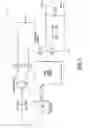
FIG. 1 is a block diagram of a circuit of converter and a fault detector of the present invention; and
FIG. 2 is a graph illustrating a peak voltage at the switching node during input rail floating.
DETAILED DESCRIPTION OF EMBODIMENTS OF THE INVENTION
FIG. 1 illustrates a converter having a PWM enabled gate driver for controlling a switching stage consisting of high- and low-side switches Q6 and Q3 connected at a switching node. A second terminal of the high-side switch is connected to an input voltage source VIN, which is connected to a grounded capacitor CIN. A second terminal of the low-side switch is connected to the ground. An inductor L is connected between the switching node and a positive output voltage terminal VOUT+, which is coupled by a capacitor COUT to a negative output voltage terminal VOUT−. A stage of series couples resistor RCS and capacitor CCS is parallel connected to the inductor L.
The present invention further includes a detection circuit comprised of a comparator 14 for comparing a voltage at the switching node, which may be scaled by a value provided by an amplifier circuit K2 connected to a positive terminal of the comparator 14, to the input voltage Vin, which may be scaled by a value provided by an amplifier circuit K1 connected to a negative terminal of the comparator 14. A capacitor CDCOUP, connected between an output terminal of the comparator 14 and an input of a rectifier 16, provides the AC component of an output signal of the capacitor CDCOUP to be rectified by the rectifier 16. A fault flag signal provided by the rectifier 16 may be used to drive fault-related circuitry of a downstream converter.
The circuit 10 uses the voltage at the switching node for comparison with the input voltage VIN scaled by the amplifier K1, the output of the comparator 14 is decoupled through a first terminal of the capacitor CDCOUP, a second terminal of the capacitor CDCOUP is connected to the rectifier 16. This arrangement extracts the AC component of the output signal from the comparator 14. This AC component may be used to signal a fault condition in the converter 10.
Input rail floating, high-side switch short or open are the most common converter fault scenarios. When the high-side switch Q6 is short or open, the output of the comparator 14 will be constant high or low, respectively. Thereafter no AC component will be fed into the rectifier 16 through the decoupling capacitor CDCOUP.
For input rail floating, illustrated in FIG. 2, in graph (a) a waveform of voltage at the switching node with floating input is displayed over a waveform of voltage at the switching node with normal input. Graph (b) illustrates a waveform of voltage at the switching node with floating input due to boost mode operation of the buck converter of FIG. 1. A peak voltage at the switching node will be less than the input voltage VIN. So a preset threshold as in graph (c) can be compared with the voltage at the switching node. This will indicate a fault to the converter.
Although the present invention has been described in relation to particular embodiments thereof, many other variations and modifications and other uses will become apparent to those skilled in the art. It is preferred, therefore, that the present invention not be limited by the specific disclosure herein.
Claims
What is claimed is:1. A circuit for detecting faults in at least one converter in a converter system, the at least one converter including a switching stage having high- and low-side switches connected at a switching node and fault circuitry for managing a plurality of fault conditions, the circuit comprising:
a gate driver circuit connected to gate terminals of the high- and low-side switches for providing PWM signals to control the switching stage;
a comparator circuit for comparing a voltage at the switching node to the input voltage and providing an output signal, the comparator circuit having output, positive and negative terminals;
a fourth capacitor connected to the output terminal of the comparator circuit to generate an AC component of the comparator circuit output signal; and
a rectifier circuit connected to the fourth capacitor for rectifying the AC component of the comparator circuit and providing a fault-indicating signal to the gate driver,
wherein the fault-indicating signal is used to drive the fault circuitry to correct a fault condition selected from the plurality of fault conditions in the converter system.
2. The circuit of claim 1, further comprising an input voltage source connected to one terminal of the high-side switch and to a grounded first capacitor.
3. The circuit of claim 3, further comprising:
positive and negative voltage output terminals interconnected by a second capacitor, the negative voltage output being connected to a second terminal of the low switch;
an inductor connected between the switching node and a positive output voltage terminal; and
a series couples resistor and third capacitor stage, the stage being parallel connected to the inductor.
4. The circuit of claim 3, further comprising a circuit connected between the switching node and a positive terminal of the comparator circuit for scaling the voltage at the switching node by a first value.
5. The circuit of claim 4, further comprising a circuit connected to a negative terminal of the comparator circuit for scaling the input voltage by a second value
6. The circuit of claim 1, wherein the plurality of fault conditions is selected from at least one of input rail floating, high-side switch gate floating, high-side switch short and high-side switch open.
7. The circuit of claim 6, wherein the AC component of the output signal is absent in situations selected from at least one of
when the high-side switch is short the output signal of the comparator circuit is constantly high and
when the high-side switch is open the output signal of the comparator circuit is constantly low.
8. The circuit of claim 6, wherein a preset threshold is compared with the voltage at the switching node to determine input rail floating which exists when a peak voltage at the switching node is less than the input voltage, the threshold is preset to the peak switching node voltage.
Images & Drawings included:


Sources:
- United States Patent and Trademark Office - verify current appl. status at the USPTO↗
Similar patent applications:
Recent applications in this class:
- » 20250279643 2025-09-04
COIL SHORT CIRCUIT PROTECTION IN DC-DC CONVERTERS - » 20250219395 2025-07-03
METHOD, CIRCUIT, AND DEVICE FOR PROTECTING MOS GROUP, AND CHARGING AND DISTRIBUTION SYSTEM - » 20250219394 2025-07-03
METHOD, CIRCUIT, AND DEVICE FOR PROTECTING MOS GROUP, AND CHARGING AND DISTRIBUTION SYSTEM - » 20250210969 2025-06-26
PRE-CHARGE CIRCUITS FOR DIRECT CURRENT BUS TRANSIENT VOLTAGE PROTECTION - » 20250210968 2025-06-26
FAULT DETECTION SYSTEM AND METHOD FOR SWITCHED CAPACITOR CONVERTER - » 20250183653 2025-06-05
ISOLATED SWITCHING CIRCUIT WITH SHORT-CIRCUIT PROTECTION AND METHOD THEREOF - » 20250125608 2025-04-17
DC:DC CONVERTER CONTROL - » 20250112454 2025-04-03
Power converter - » 20250096557 2025-03-20
DC FAULT MANAGEMENT IN ELECTRICAL POWER SYSTEM - » 20250096556 2025-03-20
HIGH VOLTAGE SIDE OVERCURRENT AND OVERVOLTAGE PROTECTION CIRCUIT
Recent applications for this Assignee:
- » 20150130036 2015-05-14
Semiconductor package with low profile switch node integrated heat spreader - » 20150037965 2015-02-05
Fabrication of III-nitride semiconductor device and related structures - » 20150008572 2015-01-08
Power semiconductor package with multiple dies - » 20150001599 2015-01-01
Power semiconductor package with non-contiguous, multi-section conductive carrier - » 20140353680 2014-12-04
Gallium nitride semiconductor structures with compositionally-graded transition layer - » 20140339686 2014-11-20
Group III-V device with a selectively modified impurity concentration - » 20140339651 2014-11-20
Semiconductor device with a field plate double trench having a thick bottom dielectric - » 20140332879 2014-11-13
Power semiconductor device with reduced on-resistance and increased breakdown voltage - » 20140327014 2014-11-06
III-nitride rectifier package - » 20140319665 2014-10-30
Power semiconductor package