Battery plug structure
US20080076271A1
2008-03-27
11/526,069
2006-09-25
✅ Patent granted
US 7,435,094 B2
2008-10-14
-
-
Renee S Luebke | Harshad C Patel
2026-09-25
Abstract:
The present invention provides an improved structure for a battery plug, wherein plug contacts are plugged into a plug socket to supply electric power, which is conducted to conducting wires. Magnets serve as electrical connecting interfaces when the conducting wires are connected to positive and negative poles and electrical contact points of a battery, Moreover, the magnets are each provided with a strong attraction function which is used to prevent the conducting wires from separating from the positive and negative poles of the battery and producing poor contact with electrical contact points of the battery. Furthermore, the magnetic magnets can be freely moved, and are not affected by shape or size of the battery or different positions and spacings of the contact points, thereby enabling the plug device to achieve multifarious electrical connecting functionality, and provides the plug device with increased originality and practicability.
Assignee:
- Jye Chuang Electronic Co., Ltd. 1 🇹🇼 Sijhih, Taiwan
Interested in similar patents?
Get notified when new applications in this technology area are published.
Classification:
H01R11/30 » CPC further
Individual connecting elements providing two or more spaced connecting locations for conductive members which are, or may be, thereby interconnected, e.g. end pieces for wires or cables supported by the wire or cable and having means for facilitating electrical connection to some other wire, terminal, or conductive member, blocks of binding posts; End pieces or tapping pieces for wires, supported by the wire and for facilitating electrical connection to some other wire, terminal or conductive member End pieces held in contact by a magnet
H01M10/48 » CPC main
Secondary cells; Manufacture thereof; Methods or arrangements for servicing or maintenance of secondary cells or secondary half-cells Accumulators combined with arrangements for measuring, testing or indicating the condition of cells, e.g. the level or density of the electrolyte
H01R11/282 » CPC further
Individual connecting elements providing two or more spaced connecting locations for conductive members which are, or may be, thereby interconnected, e.g. end pieces for wires or cables supported by the wire or cable and having means for facilitating electrical connection to some other wire, terminal, or conductive member, blocks of binding posts; End pieces or tapping pieces for wires, supported by the wire and for facilitating electrical connection to some other wire, terminal or conductive member; End pieces consisting of a ferrule or sleeve for connections to batteries comprising means for facilitating engagement or disengagement, e.g. quick release terminal
H01R13/6205 » CPC further
Details of coupling devices of the kinds covered by groups or -; Means for facilitating engagement or disengagement of coupling parts or for holding them in engagement Two-part coupling devices held in engagement by a magnet
H02J7/0045 » CPC further
Circuit arrangements for charging or depolarising batteries or for supplying loads from batteries characterised by the mechanical construction concerning the insertion or the connection of the batteries
H01R2201/16 » CPC further
Connectors or connections adapted for particular applications for telephony
Y02E60/10 » CPC further
Enabling technologies; Technologies with a potential or indirect contribution to GHG emissions mitigation Energy storage using batteries
Y02E60/10 » CPC further
Enabling technologies; Technologies with a potential or indirect contribution to GHG emissions mitigation Energy storage using batteries
Description
BACKGROUND OF THE INVENTION
(a) Field of the Invention
The present invention provides an improved structure for a battery plug, which embodies a variation in one end of a plug device, wherein magnets are used to serve as electrical connecting interfaces when conducting wires are connected to positive and negative poles and electrical contact points of a battery.
(b) Description of the Prior Art
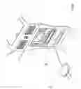
FIGS. 1 and 2 show rechargeable batteries A1 and B1, and chargers A and B of prior art respectively, and when the rechargeable batteries A1, B1 need to be charged, then the chargers A and B provided by the original manufacturers must be used to implement charging. Moreover, because of the different shapes and sizes of batteries on the market, and varied position and spacing of charge contact points A2, B2, thus, other manufacturer brand chargers are unable to substitute the chargers A, B. Hence, if the chargers A, B malfunction or are lost, then a user must request the original manufacturers to repair the chargers A, B or purchase another charger. It may also be the case that the charger models A, B are no longer produced, and thus cannot be purchased, it is bound to happen that the rechargeable batteries A1, B1 and respective chargers become obsolete and unable to be used again, resulting in great inconvenience to users and wastage.
Hence, the inventor of the present invention proposes to resolve and surmount existent technical difficulties to eliminate the aforementioned shortcomings of prior art.
SUMMARY OF THE INVENTION
The present invention provides an improved structure for a battery plug, which embodies a variation in one end of a plug device, wherein magnets are used to serve as electrical connecting interfaces when conducting wires are connected to positive and negative poles and electrical contact points of a battery. Moreover, the magnets are provided with a strong attraction function, which is used to prevent the conducting wires from separating from the positive and negative poles of the battery and producing poor contact with electrical contact points of the battery. Furthermore, the magnetic magnets can be freely moved, and are not affected by shape or size of the battery or different positions and spacings of the contact points, thereby enabling the plug device to achieve multifarious electrical connecting functionality.
To enable a further understanding of said objectives and the technological methods of the invention herein, brief description of the drawings is provided below followed by detailed description of the preferred embodiments.
BRIEF DESCRIPTION OF THE DRAWINGS
FIG. 1 shows an elevational view of prior art.
FIG. 2 shows an elevational view of another prior art.
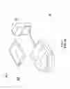
FIG. 3 shows an elevational view according to the present invention.
FIG. 4 shows an elevational view of a first embodiment according to the present invention.
FIG. 5 shows an elevational view of a second embodiment according to the present invention.
FIG. 6 shows an elevational view of a third embodiment according to the present invention.
FIG. 7 shows an elevational view of a fourth embodiment according to the present invention.
DETAILED DESCRIPTION OF THE PREFERRED EMBODIMENTS
Referring to FIG. 3, which shows an improved structure of a battery plug of the present invention, wherein a plug device C is structured to comprise plug contacts C1, display devices C2, conducting wires C3 and magnets C4.
The plug contacts C1 are located at one end of the plug device C, and are used to plug into a plug socket, thereby enabling the plug device C to supply electric power and effect charging of a battery. The conducting wires C3 are located at another end of the plug device C, and the magnets C4 are respectively connected to the conducting wires C3, thereby enabling electric power to be conducted to the magnets C4 through the conducting wires C3. The magnets C4 are each provided with a strong attraction function which enables connecting to positive and negative poles of any general rechargeable battery. Moreover, shape or size of the battery does not affect charging thereof, even different positions and spacing of contact points on the battery can be accommodated to implement charging by means of the magnets C4 being able to be freely magnetically attached to the battery according to the user. During the course of charging, the display devices C2 display the different states of the battery, including charging, discharging and saturation, thereby providing the plug device C with increased advancement and practicability.
Referring to FIGS. 4 and 5, which show embodiments of the present invention, wherein the plug contacts C1 located on the plug device C can be plugged into a plug socket, thereby enabling the plug device C to supply electric power that is conducted to the conducting wires C3. The magnets C4 connected to the conducting wires C3 are provided with a strong attraction and conducting function which enables them to be respectively disposed on contact points D1 of a rechargeable battery D, or respectively disposed on contact points E1 of a rechargeable battery E. Moreover, during the course of charging, the display devices C2 flash various light signals according to different states of the plug device C, including charging, discharging and saturation.
Referring to FIG. 6, wherein the strong magnetism of the magnets C4 is used to firmly attach to positive and negative poles of a rechargeable battery F, thereby enabling charging of the general rechargeable battery F. Moreover, the magnets C4 can be freely attached to the desired rechargeable battery F of various shapes according to the user.
Referring to FIG. 7, wherein the original plug contacts C1 (see FIG. 3) are replaced with a car charger plug G. The car charger plug G can be plugged into a car power socket, thereby supplying power to the plug device C for use thereof, and enabling a user to prepare for possible need.
In order to better explicitly disclose advancement and practicability of the present invention, a comparison with prior art is described hereinafter:
Shortcomings of Prior Art
1. Limited to use with brand and model of the manufacture's rechargeable batteries, thus prohibiting use of an all-purpose charger.
2. Requires additional purchase if lost.
3. Fatigue results in the elasticity of elastic contact points after use of the rechargeable battery and charger for a long period of time, easily causing poor electrical contact.
Advantages of the Present Invention
1. Can be freely attached to contact points of all types of rechargeable batteries, and will not easily come apart or produce poor electrical contact.
2. Is not restricted to size of battery or position of the contact points, and allows all types of rechargeable batteries to commonly use one charger or tester.
3. If jolted, the magnets C4 are immediately attracted and reattached to the contact points of the battery, thereby providing good contact ability.
4. Saves on user expenditure.
5. Provided with advancement and practicability.
6. Enhances commercial competitiveness.
In conclusion, the present invention in overcoming structural shortcomings of prior art has assuredly achieved effectiveness of anticipated advancement, and, moreover, is easily understood by persons unfamiliar with related art. Furthermore, contents of the present invention have not been publicly disclosed prior to this application, and practicability and advancement of the present invention clearly comply with essential elements as required for a new patent application. Accordingly, a new patent application is proposed herein.
It is of course to be understood that the embodiments described herein are merely illustrative of the principles of the invention and that a wide variety of modifications thereto may be effected by persons skilled in the art without departing from the spirit and scope of the invention as set forth in the following claims.
Claims
1-7. (canceled)
8. A battery plug structure, including a plug device comprising:
conducting wires comprising a positive wire connected to a positive pole and a negative wire connected to a negative pole, the positive pole and negative pole both being electrical contact points of a battery; and
magnets located at one end of each of the conducting wires as electrical connecting interfaces, the magnets attracting the electrical contact points to prevent the conducting wires from separating from the positive and negative poles of the battery,
wherein the magnets are freely movable and connecting to electrical contact points is not preventing by shape or size of the battery or different positions and spacings of the contact points.
9. The battery plug structure according to claim 8, wherein the magnets connected to battery contact points serve as connecting elements to charge devices, discharge devices, or devices to measure voltage, current, or internal resistance of the battery.
10. The battery plug structure according to claim 8, wherein the plug device is configured with display devices, and the display devices are LEDs (light-emitting diodes), LCDs (liquid crystal displays), light bulbs, speakers, voltmeters, ammeters, impedance meters, or image devices.
11. The battery plug structure according to claim 8, wherein a number of the conducting wires is more than two.
12. The battery plug structure according to claim 8, wherein plug contacts are configured as a car charger plug or an USB (universal serial bus) connector.
Images & Drawings included:


Sources:
- United States Patent and Trademark Office - verify current appl. status at the USPTO↗
Similar patent applications:
Recent applications in this class:
- » 20250293326 2025-09-18
METHOD AND SYSTEM FOR DETECTING BATTERY DEFECT IN FORMATION PROCESS - » 20250266518 2025-08-21
CELL CONFIGURED FOR PENETRATION TEST - » 20250239669 2025-07-24
SYSTEMS AND METHODS FOR GENERATING ROLL MAP AND MANUFACTURING BATTERY USING ROLL MAP - » 20250238111 2025-07-24
SYSTEMS AND METHODS FOR GENERATING ROLL MAP AND MANUFACTURING BATTERY USING ROLL MAP - » 20250233218 2025-07-17
Pouch-Shaped Battery Cell and Battery Module Including the Same - » 20250226466 2025-07-10
PRESSURE-MONITORING FOR ELECTROCHEMICAL CELLS AND RELATED DEVICES AND SYSTEMS - » 20250210739 2025-06-26
BATTERY HOUSING STRUCTURE - » 20250201951 2025-06-19
POWER STORAGE APPARATUS - » 20250192255 2025-06-12
BATTERY SYSTEM - » 20250192254 2025-06-12
BATTERY MANAGEMENT SYSTEM, BATTERY PACK, ELECTRIC VEHICLE, AND BATTERY MANAGEMENT METHOD