Ball grid array socket having a positioning device
US20080108237A1
2008-05-08
11/982,963
2007-11-06
✅ Patent granted
US 7,435,103 B2
2008-10-14
-
-
Neil Abrams | Phuong Nguyen
2027-11-06
Abstract:
An electrical connector (2) comprises an insulative housing (4) and a number of metal plates (3). The insulative housing (4) has a bottom floor (45) and a number of side walls (46) extending perpendicularly from the bottom floor (45). The bottom floor (45) and the side walls (46) define a cavity (44) and an opening opposite the bottom floor (45) so that a chipset (8) could be loaded into the cavity (44) through the opening. Each of the metal plates (3) comprises a base portion (30) fixing the metal plate (3) to the insulative housing (4), a spring arm (31) extending from the base portion (30) and a pressing pad (32) connecting the spring arm (31) for flexibly abutting a side of the chipset (8).
Assignee:
- Hon Hai Precision Ind. Co., Ltd. 1,929 🇹🇼 Taipei Hsien, Taiwan
Interested in similar patents?
Get notified when new applications in this technology area are published.
Classification:
H01R12/7005 » CPC main
Structural associations of a plurality of mutually-insulated electrical connecting elements, specially adapted for printed circuits, e.g. printed circuit boards [PCBs], flat or ribbon cables, or like generally planar structures, e.g. terminal strips, terminal blocks; Coupling devices specially adapted for printed circuits, flat or ribbon cables, or like generally planar structures; Terminals specially adapted for contact with, or insertion into, printed circuits, flat or ribbon cables, or like generally planar structures; Coupling devices Guiding, mounting, polarizing or locking means; Extractors
H01R12/7076 » CPC further
Structural associations of a plurality of mutually-insulated electrical connecting elements, specially adapted for printed circuits, e.g. printed circuit boards [PCBs], flat or ribbon cables, or like generally planar structures, e.g. terminal strips, terminal blocks; Coupling devices specially adapted for printed circuits, flat or ribbon cables, or like generally planar structures; Terminals specially adapted for contact with, or insertion into, printed circuits, flat or ribbon cables, or like generally planar structures; Coupling devices for connection between PCB and component, e.g. display
H01R13/15 IPC
Details of coupling devices of the kinds covered by groups or -; Contact members Pins, blades or sockets having separate spring member for producing or increasing contact pressure
H01R13/40 IPC
Details of coupling devices of the kinds covered by groups or - Securing contact members in or to a base or case; Insulating of contact members
H01R12/00 IPC
Structural associations of a plurality of mutually-insulated electrical connecting elements, specially adapted for printed circuits, e.g. printed circuit boards [PCBs], flat or ribbon cables, or like generally planar structures, e.g. terminal strips, terminal blocks; Coupling devices specially adapted for printed circuits, flat or ribbon cables, or like generally planar structures; Terminals specially adapted for contact with, or insertion into, printed circuits, flat or ribbon cables, or like generally planar structures
Description
BACKGROUND OF THE INVENTION
1. Field of the Invention
The present invention relates to an electrical connector, and more particularly, relates to an electrical connector having a device for positioning an electrical element received in the electrical connector.
2. Description of the Prior Art
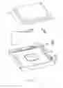
An electrical connector 9 related to present invention is disclosed in FIG. 1. The electrical connector 9 includes an insulative housing 10 and a grid array of conductive contacts 110 received in the insulative housing 10. The insulative housing 10 forms a base portion 13 and four side walls 12 to define a cavity 15 for receiving a chipset 8. Adjacent two of the side walls 12 respectively form spring arms 120, 120′ for flexibly abutting the chipset 8 against the corresponding side walls 12. However, the insulative housing 10 is difficult to be integrally injection-molded. Furthermore, the spring arms 120, 120′ are integrally made from polymer, so, when the chipset 8 is loaded and unloaded in more circles, the spring arms 120 may become tired or even broken from the side walls 12 so that the chipset 8 can not be positioned in the right place in the cavity 15.
BRIEF SUMMARY OF THE INVENTION
Therefore, one object of the present invention is to provide a electrical connector having durable positioning device.
An electrical connector according to the present invention comprises an insulative housing having a bottom floor and a plurality of side walls extending perpendicularly from the bottom floor, the bottom floor and the side walls defining a cavity and an opening opposite the bottom floor so that an electrical element could be uploaded into the cavity through the opening; a metal plate, the metal plate comprising a base portion fixing the metal plate to the insulative housing, a spring arm extending from the base portion and a pressing pad connecting the spring arm for flexibly abutting a side of the electrical element.
Other objects, advantages and novel features of the invention will become more apparent from the following detailed description of the present embodiment when taken in conjunction with the accompanying drawings.
BRIEF DESCRIPTION OF THE DRAWINGS
The features of this invention which are believed to be novel are set forth with particularity in the appended claims. The invention, together with its objects and the advantages thereof, may be best understood by reference to the following description taken in conjunction with the accompanying drawings, in which like reference numerals identify like elements in the figures and in which:
FIG. 1 is a perspective view of an electrical connector related to the present invention;
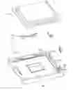
FIG. 2 is an explosive view of an electrical connector according to a first embodiment of the present invention;
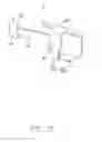
FIG. 3 is a perspective view of a metal plate shown in FIG. 1;
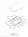
FIG. 4 is a perspective view of the electrical connector shown in FIG. 2, with a chipset received therein;
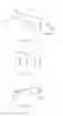
FIG. 5 is a perspective view of a metal plate according to a second embodiment of the present invention;
FIG. 6 is a perspective view of a metal plate according to a third embodiment of the present invention; and
FIG. 7 is a perspective view of a metal plate according to a fourth embodiment of the present invention.
DETAILED DESCRIPTION OF THE INVENTION
Reference will now be made to the drawing figures to describe the present invention in detail.
As shown in FIG. 2, the electrical connector of the present invention is used for connecting a chipset 8 to a printed circuit board (not shown). The electrical connector 2 includes an insulative housing 4 and four metal plates 3.
The insulative housing 20 forms a bottom floor 45 and four side walls 46 defining a cavity 44 and a opening opposite to the bottom floor 45. Adjacent two of the side walls 46 define sunken portions 42, 43 for receiving the metal plates. The bottom floor 45 defines securing holes 41 for interferentially mating with the metal plates 3.
As shown in FIG. 3, each of the metal plates 30 comprises a base portion 30, a spring arm 31 extending from the base portion 30, a pressing pad 32 connected to a tip end of the spring arm 31 and a guiding portion 33. The base portion 30 further includes a U-shaped clipping portion 34 and a securing portion 300 having a tab 302 and stubs 301.
Since the fatigue strength of the metal is much high than the polymer, so the durability of the metal plate 3 for positioning the chipset 8 in the electrical connector 2 is much better than that of the spring arms 120, 120′ of the electrical connector 9. Furthermore, the spring arms 31 are not injection-molded integrally with the insulative housing 4, which makes the insulative housing 4 easy to be injection-molded.
Referring to FIG. 5, a metal plate 5 forms a base portion 50, a straight spring arm 51 and a pressing pad 52. The base portion 50 further includes a supporting board 54 connecting the spring arm 51 and a securing portion 500 straightly extending from an edge of the supporting board 54.
Referring to FIG. 6, a metal plate 6 according to a third embodiment is similar to the metal plate 5 except that an actuate spring arm 61 substitutes for the straight spring arm 51.
Referring to FIG. 7, a metal plate 7 according to a fourth embodiment is similar to the metal plate 5 except that a securing portion 700 is perpendicularly bent from a supporting board 74.
It is to be understood, however, that even though numerous, characteristics and advantages of the present invention have been set fourth in the foregoing description, together with details of the structure and function of the invention, the disclosed is illustrative only, and changes may be made in detail, especially in matters of number, shape, size, and arrangement of parts within the principles of the invention to the full extent indicated by the broad general meaning of the terms in which the appended claims are expressed.
Claims
We claim:1. An electrical connector comprising:
an insulative housing having a bottom floor and a plurality of side walls extending perpendicularly from the bottom floor, the bottom floor and the side walls defining a cavity and an opening opposite the bottom floor for receiving an electrical element; and
a metal plate comprising a base portion fixed to the insulative housing, a spring arm extending from the base portion and a pressing pad connecting the spring arm for flexibly abutting a side of the electrical element.
2. The electrical connector according to claim 1, wherein the insulative housing has four side walls disposed in a rectangle and there are four metal plates mounted in adjacent two of the four side walls.
3. The electrical connector according to claim 1, wherein the base portion of the metal plate comprises a securing portion interferentially mating into a hole defined in the insulative housing and a clipping portion having a pair of parallel boards for clipping a portion of the side walls.
4. The electrical connector according to claim 1, wherein the base portion of the metal plate includes a securing portion interferentially mating into a hole defined in the bottom floor of the insulative housing and a supporting board parallely abutting one of the side walls.
5. The electrical connector according to claim 1, wherein the base portion of the metal plate includes a securing portion interferentially mating into a hole defined in one of the side walls of the insulative housing and a supporting board parallely abutting one of the side walls.
6. The electrical connector according to any one of claim 1, wherein the metal plate comprises a spring arm extending slant wisely from the base portion with respect to a corresponding side wall into the cavity.
7. The electrical connector according to claim 1, wherein the metal plate further comprises a guiding portion connector to the pressing pad.
8. The electrical connector according to claim 6, wherein the securing portion comprises a tab portion and a plurality of stubs extending sidewise from the tab portion.
9. An electrical connector assembly comprising:
an insulative housing having a plurality of side walls and a bottom wall commonly defining a receiving cavity therein;
an electronic package received in said receiving cavity;
at least one side wall defining an interior face intimately confronting a side edge of the electronic package;
a recess formed beside said abutment interior face and offset from said interior face in an outward direction; and
a discrete metallic piece located in said recess and defining a spring arm abutting against said side edge and imposing a force thereon.
10. The connector assembly as claimed in claim 9, wherein the metallic piece further includes a pressing pad abutting against the side edge, and said pressing pad defines an upward leading section.
11. The connector assembly as claimed in claim 9, wherein the metallic piece includes a secured to the housing on an interior side of the side wall.
12. The connector assembly as claimed in claim 11, wherein said metallic piece further includes a plate located on an exterior side of the side wall.
13. An electrical connector for receiving an electronic package, comprising:
an insulative housing having a plurality of side walls and a bottom wall commonly defining a receiving cavity therein;
at least one side wall defining an interior face for intimately confronting a side edge of the electronic package;
a recess formed beside said abutment interior face and offset from said interior face in an outward direction; and
a discrete metallic piece located in said recess and defining a spring arm abutting against said side edge and imposing a force thereon.
14. The connector assembly as claimed in claim 13, wherein the metallic piece further includes a pressing pad abutting against the side edge, and said pressing pad defines an upward leading section.
15. The connector assembly as claimed in claim 14, wherein the metallic piece includes a secured to the housing on an interior side of the side wall.
16. The connector assembly as claimed in claim 15, wherein said metallic piece further includes a plate located on an exterior side of the side wall.
Images & Drawings included:

Sources:
- United States Patent and Trademark Office - verify current appl. status at the USPTO↗
Recent applications in this class:
- » 20250219308 2025-07-03
ELECTRICAL CONNECTOR STRUCTURE - » 20250079733 2025-03-06
CABLE CARRIER ADAPTER FOR CONNECTIVITY TO CIRCUIT BOARD AND CONNECTOR - » 20240283175 2024-08-22
CONNECTOR - » 20230318209 2023-10-05
CABLE CONNECTOR AND CONNECTOR ASSEMBLY - » 20230307855 2023-09-28
Connector Device - » 20230187857 2023-06-15
CONNECTOR ASSEMBLY - » 20230126150 2023-04-27
ELECTRICAL CONNECTOR - » 20230106932 2023-04-06
Guide module with integrated connector protection - » 20230040942 2023-02-09
Wire-to-circuit board connection structure and a circuit board-attached cable - » 20220336976 2022-10-20
RECEPTACLE COUPLER FOR COMMUNICATION SYSTEM
Recent applications for this Assignee:
- » 20110045702 2011-02-24
Electrical cable connector assembly with improved wire organizer - » 20110021088 2011-01-27
Electrical connector with improved contact footprints - » 20110021082 2011-01-27
High density backplane connector having improved terminal arrangement - » 20110008982 2011-01-13
N-in-1 card connector - » 20110005825 2011-01-13
Cable assembly with EMI protection - » 20110003508 2011-01-06
Electrical connector rotatably mounted to a portable device - » 20100330822 2010-12-30
Electrical connector having contact with upper terminal and lower terminal - » 20100317218 2010-12-16
Electrical connector assembly with latching mechanism - » 20100297861 2010-11-25
Socket connector having improved actuating mechanism for driving moving plate - » 20100291799 2010-11-18
Shielded connector with enlarged base supporting cantilevered brackets extending from the shielded connector