Molded plastic container and preform having insert-molded RFID tag
US20080131629A1
2008-06-05
11/607,523
2006-12-01
✅ Patent granted
US 7,850,893 B2
2010-12-14
-
-
Christina Johnson | Galen Hauth
2027-06-25
Abstract:
An RFID assembly includes an RFID inlay, with an RFID tag, encapsulated within a plastic housing. The housing has a peripheral array of flexible resilient fingers for mounting the housing within a pocket on a support structure, such as a pocket on a mold core. The pocket preferably is on an end of the mold core so that the RFID assembly preferably is disposed substantially beneath the end surface of the mold core. Plastic material, which preferably is the same plastic material as forms the plastic housing in which the inlay is contained, can be injected into a mold cavity surrounding the mold core and the assembly housing without eroding the material of the housing.
Inventors:
- Brian J. Chisholm 37 🇺🇸 Sylvania, OH, United States
- Douglas W. Abbott 5 🇺🇸 Bowling Green, OH, United States
Assignee:
- Rexam Healthcare Packaging Inc. 31 🇺🇸 Perrysburg, OH, United States
Interested in similar patents?
Get notified when new applications in this technology area are published.
Classification:
B65D1/00 » CPC main
Containers having bodies formed in one piece, e.g. by casting metallic material, by moulding plastics, by blowing vitreous material, by throwing ceramic material, by moulding pulped fibrous material, by deep-drawing operations performed on sheet material
B65D1/00 » CPC main
General kinds of rigid or semi-rigid containers
B29C45/14065 » CPC further
Injection moulding, i.e. forcing the required volume of moulding material through a nozzle into a closed mould; Apparatus therefor incorporating preformed parts or layers, e.g. injection moulding around inserts or for coating articles Positioning or centering articles in the mould
B29C49/20 » CPC further
Blow-moulding, i.e. blowing a preform or parison to a desired shape within a mould; Apparatus therefor of articles having inserts or reinforcements ; Handling of inserts or reinforcements
G06K19/07724 » CPC further
Record carriers for use with machines and with at least a part designed to carry digital markings characterised by the kind of the digital marking, e.g. shape, nature, code; Record carriers with conductive marks, printed circuits or semiconductor circuit elements, e.g. credit or identity cards also with resonating or responding marks without active components with integrated circuit chips; Constructional details, e.g. mounting of circuits in the carrier; Physical layout of the record carrier the record carrier being at least partially made by a molding process
B29B11/08 » CPC further
Making preforms by moulding the material Injection moulding
B29B11/14 » CPC further
Making preforms characterised by structure or composition
B29C49/06 » CPC further
Blow-moulding, i.e. blowing a preform or parison to a desired shape within a mould; Apparatus therefor; Combined blow-moulding and manufacture of the preform or the parison Injection blow-moulding
B29C49/24 » CPC further
Blow-moulding, i.e. blowing a preform or parison to a desired shape within a mould; Apparatus therefor Lining or labelling
B29C2045/14131 » CPC further
Injection moulding, i.e. forcing the required volume of moulding material through a nozzle into a closed mould; Apparatus therefor incorporating preformed parts or layers, e.g. injection moulding around inserts or for coating articles; Positioning or centering articles in the mould using positioning or centering means forming part of the insert
B29C2045/14852 » CPC further
Injection moulding, i.e. forcing the required volume of moulding material through a nozzle into a closed mould; Apparatus therefor incorporating preformed parts or layers, e.g. injection moulding around inserts or for coating articles incorporating articles with a data carrier, e.g. chips
B29C2049/2008 » CPC further
Blow-moulding, i.e. blowing a preform or parison to a desired shape within a mould; Apparatus therefor of articles having inserts or reinforcements ; Handling of inserts or reinforcements inside the article
B29K2105/253 » CPC further
Condition, form or state of moulded material or of the material to be shaped; Solid Preform
B65D2203/10 » CPC further
Decoration means, markings, information elements, contents indicators Transponders
Y10T428/13 » CPC further
Stock material or miscellaneous articles Hollow or container type article [e.g., tube, vase, etc.]
B65D25/10 IPC
Details of other kinds or types of rigid or semi-rigid containers; Internal fittings Devices to locate articles in containers
G06K19/06 IPC
Record carriers for use with machines and with at least a part designed to carry digital markings characterised by the kind of the digital marking, e.g. shape, nature, code
Description
The present disclosure relates to manufacture of a molded plastic container having a radio frequency identification (RFID) tag insert molded into a wall of the container, to manufacture of a preform for blow molding into a plastic container and having an RFID tag insert molded into a wall of the preform, and to an RFID assembly for insert molding into the wall of a container or a container preform.
BACKGROUND AND SUMMARY OF THE DISCLOSURE
It has been proposed to place an RFID tag on or in a wall of a container to confirm the genuineness of the package that includes the container and/or to provide other information concerning the package or a product within the package. Such RFID tag can be secured to a wall of the container after fabrication of the container, embedded in a wall of the container during blow molding of the container, or assembled to a container preform in such a way that the tag will be embedded in a wall of the container following blow molding of the preform.
U.S. application Ser. No. 11/348,662 filed Feb. 7, 2006 discloses a method of making a plastic container having an RFID tag in a wall of the container by providing a mold that includes a mold core and mounting on the mold core an insert that includes an RFID tag. A plastic preform is formed in the mold around the mold core and insert such that the insert is embedded in a wall of the preform. The preform can be blow molded into a plastic container having the insert embedded in a wall of the container. In two exemplary embodiments disclosed in the noted application, the insert is mounted on the mold core by the heat of the mold core that causes the insert to adhere to the mold core, or by means of an embossment on the insert being press fit into a pocket on the mold core. A general object of the present disclosure is to provide a method of making a container and/or a container preform in which the RFID insert is reliably mounted on the mold core, and/or to provide an RFID insert for mounting on the mold core.
The present disclosure embodies a number of aspects that can be implemented separately from or in combination with each other.
An RFID assembly, in accordance with one aspect of the present disclosure, includes an RFID inlay, with an RFID tag, encapsulated within a plastic housing. The housing has a peripheral array of flexible resilient fingers for mounting the housing within a pocket on a support structure, such as a pocket on a mold core. The pocket preferably is on an end of the mold core so that the RFID assembly preferably is disposed substantially beneath the end surface of the mold core. Plastic material, which preferably is the same plastic material as forms the plastic housing in which the inlay is contained, can be injected into a mold cavity surrounding the mold core and the assembly housing without eroding the material of the housing.
BRIEF DESCRIPTION OF THE DRAWINGS
The disclosure, together with additional objects, features, advantages and aspects thereof, will best be understood from the following description, the appended claims and the accompanying drawings, in which:
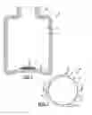
FIG. 1 is a sectional view of a blow molded plastic container in accordance with an exemplary embodiment of the present disclosure;
FIG. 2 is a top plan view of an RFID assembly in accordance with the exemplary embodiment of the present disclosure;
FIG. 3 is a sectional view taken substantially along the line 3-3 in FIG. 2;
FIG. 4 is a plan view of the RFID inlay in the RFID assembly of FIGS. 2 and 3;
FIG. 5 is a sectional schematic illustration of an apparatus for molding a container preform in accordance with an aspect of the present disclosure; and
FIG. 6 is a sectional view of an exemplary container preform made in the apparatus of FIG. 5 for blow molding the plastic container of FIG. 1.
DETAILED DESCRIPTION OF PREFERRED EMBODIMENTS
FIG. 1 illustrates a container 20 in accordance with an exemplary embodiment of the present disclosure. Container 20 includes a body with a sidewall 22 that connects a bottom wall 24 to a neck finish 26. Sidewall 22 can be of any suitable geometry, such as cylindrical. Bottom wall 24 is illustrated as having a center push-up, although this is not necessary to the present disclosure. Sidewall 22, bottom wall 24 and neck finish 26 can be of any suitable geometry and can have any suitable embossments or other features. In applications in which container 20 is for a consumable product, at least inside surface 28 of the container body preferably would be of a material approved by the FDA for contact with the consumable product in question. Container 20, including neck finish 26, sidewall 22 and/or bottom wall 24 can be of monolayer or multilayer construction. Neck finish 26 can be absent in some containers.
An RFID assembly 30 is insert molded into a wall of container 20, preferably bottom wall 24. RFID assembly 30 is illustrated in greater detail in FIGS. 2-4 as including an RFID inlay 32 disposed within a plastic housing 34. Plastic housing 34 preferably is molded around inlay 32, although housing 34 could be of multi-piece construction assembled to enclose inlay 32. An exemplary inlay 32 is illustrated in FIG. 4 as including an RFID tag or circuit 36 coupled to an rf antenna 38 and mounted on a substrate 40. The illustrated geometries of tag 36, antenna 38 and substrate 40 are exemplary only.
Housing 34, whether of unitary or multi-piece construction, preferably is circular in geometry as best seen in FIG. 2. A flange 42 extends radially outwardly from the periphery of housing 34, preferably at the midplane of housing 34. Flange 42 has a number of angularly spaced radially inwardly extending serrations or scallops 44 that effectively divide flange 42 into a plurality of angularly spaced radially outwardly extending flexible resilient fingers 46. Fingers 46 preferably have outer edges on a common circle of revolution coaxial with housing 34 and are flexible substantially independently of each other. Fingers 46 preferably are disposed in an array extending around the periphery of housing 34. Fingers 46 preferably lie in a common plane, but could be conical or propeller-shaped for example.
To form a plastic container, RFID assembly 30 is placed within a pocket 48 on the surface of a mold core 50. Pocket 48 preferably is disposed on the end of core 50, although pocket 48 could be on a side surface of the core. Pocket 48 preferably is circular in geometry and is sufficiently deep to receive substantially the entire height of assembly 30 so that housing 34 is disposed substantially beneath the end surface 52 of core 50. Assembly 30 is retained within pocket 48 by flexure of fingers 46 during insertion of assembly 30 into the pocket so that the fingers 46 retard removal of the assembly from the pocket.
With RFID assembly 30 thus firmly secured to core 50, core 50 is inserted into a mold 54 (FIG. 5) so as to form a mold cavity 56 around core 50 and assembly 30. Resin is then injected from a suitable source 58 into cavity 56 around core 50 and RFID assembly 30 to form a preform 60 (FIG. 6) in which RFID assembly 30 is embedded by insert molding, preferably within the end wall 62 of the preform. Preform 60 can be removed from core 50 for later processing in a reheat blow molding operation, or can be moved on core 50 to a blow mold station for blow molding container 20 (FIG. 1) in an injection blow molding operation.
A particular advantage of the exemplary embodiment of the disclosure illustrated in the drawings is that RFID assembly 30 is recessed with respect to end surface 52 of core 50 as resin material is injected from source 58 into mold cavity 56. This disposition of RFID assembly 30 during resin injection reduces or eliminates the tendency of the injected resin material to erode the material of RFID assembly plastic housing 34. RFID assembly plastic housing 34 can be of lower temperature plastic material, preferably the same plastic material as is injected from source 58. In other words, the plastic material of housing 34 can be the same as the plastic material of preform 60 and container 20. This eliminates issues of FDA regulations regarding material that can come into contact with the product, such as a consumable product, within the final container.
There thus have been disclosed an RFID assembly, a method of molding an RFID tag into a container, and a preform and a container made by such method, which fully satisfy all of the objects and aims previously set forth. The disclosure has been presented in conjunction with an exemplary embodiment, and additional modifications and variations have been discussed. Other modifications and variations readily will suggest themselves to persons of ordinary skill in the art in view of the foregoing description. The disclosure is intended to embrace all such modifications and variations as fall within the spirit and broad scope of the appended claims.
Claims
1. An RFID assembly that includes an RFID inlay, with an REID tag, encapsulated within a plastic housing, said plastic housing having a peripheral array of flexible resilient fingers for mounting said housing within a pocket on a support structure.
2. The assembly set forth in claim 1 wherein said housing has a circular periphery and said fingers extend from said circular periphery.
3. The assembly set forth in claim 2 wherein said fingers are disclosed in an array extending around said periphery of said housing.
4. The assembly set forth in claim 3 wherein said housing includes a radially outwardly extending peripheral flange and said fingers comprise angularly spaced portions of said flange.
5. A method of molding an RFID tag into a container, which includes the steps of:
(a) providing a mold that includes a mold core and a mold cavity,
(b) providing an RFID assembly as set forth in claim 1,
(c) mounting said RFID assembly within a pocket on said mold core by releasably engaging said fingers with a periphery of said pocket,
(d) inserting said mold core into said mold cavity, and
(e) molding a container preform in said mold cavity around said mold core and said RFID assembly.
6. The method set forth in claim 5 wherein said step (e) is carried out by injection molding.
7. The method set forth in claim 6 wherein said pocket is of an end of said mold core.
8. The method set forth in claim 7 wherein said plastic housing is of a predetermined plastic material, and wherein said step (e) is carried out by injecting the same said predetermined plastic material into said mold cavity around said mold core and said assembly.
9. The method set forth in claim 8 including:
(f) blow molding said preform into a hollow plastic container.
10. A blow molded plastic container made in accordance with the method set forth in claim 9.
11. A container preform for blow molding into a hollow plastic container and made in accordance with the method set forth in claim 8.
12. A container for a consumable product, which includes:
a container body having an inside surface of a predetermined plastic material and an RFID tag in said body encapsulated in a housing of said predetermined plastic material.
13. The container set forth in claim 12 wherein said RFID tag and said housing are in a bottom wall of said container.
14. A method of making a container for a consumable product, which includes the steps of:
(a) providing an RFID tag encapsulated within a housing of a predetermined plastic material, and
(b) molding a plastic container of said predetermined plastic material around said housing.
15. The method set forth in claim 14 wherein said step (b) includes the steps of:
(b1) mounting said housing in a pocket on an end of a mold core,
(b2) placing said mold core within a mold cavity, and
(b3) injecting said predetermined plastic material into said mold cavity around said core and said housing.
16. The method set forth in claim 15 including:
(b4) removing a preform formed in said step (b3) from said mold core, and
(b5) blow molding said preform into a container with said housing and said RFID tag embedded in a bottom wall of said container.
Images & Drawings included:


Sources:
- United States Patent and Trademark Office - verify current appl. status at the USPTO↗
Similar patent applications:
Recent applications in this class:
- » 20140216976 2014-08-07
COVERS AND MOUNTS FOR ELECTRONIC DEVICES - » 20140116908 2014-05-01
Card product package assembly having enhanced security - » 20130186799 2013-07-25
Articles prepared from thermoplastic compositions, and method of preparing such articles - » 20130180882 2013-07-18
DISPLAY DEVICE WITH FLEXIBLE DISPLAY - » 20110049150 2011-03-03
Packaging Container - » 20070164056 2007-07-19
Container - » 20060027595 2006-02-09
Container
Recent applications for this Assignee:
- » 20110139742 2011-06-16
Child-resistant closure shell, closure, and package - » 20110006030 2011-01-13
Child resistant closure with a stacking position - » 20100321160 2010-12-23
Plastic container and method of manufacture having molded-in-security features - » 20100236090 2010-09-23
Multilayer plastic container and method of storing lyophilized products - » 20100147732 2010-06-17
Child-resistant dispensing closures and closure components - » 20100126955 2010-05-27
Child-resistant container having a deflectable release - » 20100059519 2010-03-11
Closure with stopping mechanism - » 20100059518 2010-03-11
Closure with stopping mechanism - » 20090242446 2009-10-01
Attachment of an RFID tag to a container - » 20090032486 2009-02-05
Two-piece child-resistant closure and package