Structure of steppers
US20080132387A1
2008-06-05
11/645,517
2006-12-27
Abstract:
This invention is to introduce an improved structure of steppers (fitness equipment). The improved structure comprises: a main base, a supporting stand at the front end of the main base, and a cross bar that is positioned on top of and cross over the supporting stand. Two stepping bars are symmetrically installed on both sides of the cross bar, and on the stepping bars set several equally spaced lock holes for fixing stepping mats; each of the two symmetric stepping mats has a pair of properly spaced connectors at the bottom that fixes stepping mats on two lock holes of stepping bars, which enables swing curve length of the stepping mats adjustable due to multiple choices of lock holes for fixture.
Interested in similar patents?
Get notified when new applications in this technology area are published.
Classification:
A63B22/0056 » CPC main
Exercising apparatus specially adapted for conditioning the cardio-vascular system, for training agility or co-ordination of movements with cantilevered support elements pivoting about an axis the pivoting movement being in a vertical plane, e.g. steppers with a horizontal axis
A63B21/4047 » CPC further
Exercising apparatus for developing or strengthening the muscles or joints of the body by working against a counterforce, with or without measuring devices; Interfaces with the user related to strength training; Details thereof characterised by the movements of the interface Pivoting movement
A63B21/0083 » CPC further
Exercising apparatus for developing or strengthening the muscles or joints of the body by working against a counterforce, with or without measuring devices using hydraulic or pneumatic force-resisters of the piston-cylinder type
A63B21/0087 » CPC further
Exercising apparatus for developing or strengthening the muscles or joints of the body by working against a counterforce, with or without measuring devices using hydraulic or pneumatic force-resisters using pneumatic force-resisters of the piston-cylinder type
A63B22/0015 » CPC further
Exercising apparatus specially adapted for conditioning the cardio-vascular system, for training agility or co-ordination of movements with an adjustable movement path of the support elements
A63B69/22 IPC
Training appliances or apparatus for special sports; Punching balls, e.g. for boxing; Other devices for striking used during training of combat sports, e.g. bags mounted on, or suspended from, a fixed support
Description
FIELD OF THE INVENTION
This invention is to introduce an improved structure of steppers with capability of adjustable swing curve length.
BACKGROUND OF THE INVENTION
According to patent publications up to date, all proposed structures of steppers employ permanent fixture between stepping mats and stepping bars despite of differences of design on other parts, which makes swing curve length unadjustable no matter of vertical or horizontal swings. This is so because the stepping mats are permanently fixed with stepping bars, the distance between stepping mats and the pivot will be always the same. Such design has been in market for long, and familiarized by the industry.
Throughout rigorous tests and researches, the inventor finally devised a structural improvement on the steppers that solve the aforementioned problems, and thus hereby file a patent application based on the absolute novelty and capability of industrial application of the invention.
SUMMARY OF THE INVENTION
This invention is to introduce a new structure of steppers that enables swing curve length of stepping adjustable.
To reach the aforementioned function, this invention provides a structural improvement for steppers. The stepper comprises a main base, a supporting stand at the front end of the main base, and a cross bar that is positioned on top of and cross over the supporting stand. Two stepping bars are symmetrically installed on both sides of the cross bar, and on the stepping bars set several equally spaced lock holes for fixing stepping mats; Each of the two symmetric stepping mats has a pair of properly spaced connectors at the bottom that fixes stepping mats on two lock holes of stepping bars, which enables swing curve length of the stepping mats adjustable due to multiple choices of lock holes for fixture.
BRIEF DESCRIPTION OF THE DRAWINGS
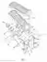
FIG. 1—a breakdown view of the exemplary embodiment for the invention
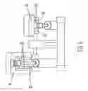
FIG. 2—a put-up bird view of the exemplary embodiment for the invention
FIG. 3—a partial sectional view of the exemplary embodiment for the invention
FIG. 4—an overview of the swing of stepping mats
FIG. 5—an overview of another structure of the stepping mats
FIG. 6—an overview of a put-up stepper using the stepping mats shown in FIG. 5
DETAILED DESCRIPTION OF THE PREFERRED EMBODIMENT
Please read the description of an exemplary embodiment as follows with references to FIGS. 1, 2, 3 and 4. This invention provides a structural improvement for steppers. The proposed stepper structure comprises a main base 10, a supporting stand 11 at one end of the main base, and a cross bar 12 that is positioned on top of and cross over the supporting stand, which provides pivots for two stepping bars 20 to rotate; The two stepping bars 20 have fitting tubes 21 in one end that are used to fit stepping bars 20 on the cross bars 12. Two bearings 22 are set between the fitting tubes 21 and the cross bar 12 separately to enable smooth rotation of the stepping bars 20; Two stepping mats 30 are connected to the top of the two stepping bars 20 separately; Two cylinder dampers 40 are connected between the main base 10 and the stepping bars 20 separately to serve as cushions; The features of such structure further comprises: the stepping bars 20 have equally-spaced lock holes 23 in a row on top of it, and each lock hole 23 sets at least one fastening groove 231.
Two properly spaced connectors are set at the bottom of each stepping mat 30 for inserting into two lock holes 23 of a stepping bar 20, and a convex ring 311 is set around each connector 31 for fitting with the fastening groove 231 inside the lock hole 23; With aforementioned components and structure, the swing curve length of the stepping mats 30 is adjustable when the connectors 31 of stepping mats 30 are inserted into different pair of lock holes 23; As shown in FIG. 4, the closer the stepping mat 30 is to the fitting tube 21 of the stepping bar 20, the shorter the swing curve length will be. (Shown as the double curved arrows); And the farther the stepping mat 30 is to the fitting tube 21 of the stepping bar 20, the longer the swing curve length will be;
Therefore, this invention proposes a new stepper structure that completely revolutionizes the traditional one, enabling users' feet to exercise at different swing curves simultaneously while still keeping traditional stepper structure available. This is the main improvement point of this invention.
In this invention, the connector 31 at the bottom of a stepping mat 30 could be also a short rod that has a groove in the center, so that it can insert into lock hole 23 of stepping bar 20 conveniently and rapidly. Moreover, FIGS. 5 and 6. indicate another equivalent embodiment of this invention. In order to fix stepping mats 30 with stepping bars 20 more firmly, especially two symmetric fitting boards 32 are set at the bottom of the stepping mats 30, and the distance between the two fitting boards 32 is equal to the width of the stepping bar 20. The fitting boards 32 are employed to fit against both sides of the stepping bar 20 to make sure the fixture of two connectors 31 and lock holes 23 of the stepping bars 20 more firmly.
With all aforementioned, the invention deserves grant of a patent based on its capability of industrial application and absolute novelty. The example illustrated above is just an exemplary embodiment for the invention, and shall not be utilized to confine the scope of the patent. Any equivalent modifications within the scope of claims of the patent shall be covered in the protection for this patent.
Claims
What is claimed is:1. An improved structure of steppers comprises: a main base, a cross bar set in one end of the said main base; Two stepping bars are symmetrically installed on both sides of the said cross bar; two stepping mats are connected to the top of the said two stepping bars separately; two cylinder dampers are connected between the said main base and the said two stepping bars separately; the features comprises: each of the said stepping bars has several equally spaced lock holes in a row; each of the said stepping mats has a pair of properly spaced connectors at the bottom for fixing each of the said stepping mats on two lock holes of each of the said stepping bars; the swing curve length of the said stepping mats can adjusted by fitting the said connectors of the said stepping mats into different said lock holes of the said stepping bars.
2. The improved structure of steppers of claim 1, wherein each said lock hole of the said stepping bars has at least one fastening groove, and a convex ring is set on each said connector for fitting with the said fastening groove inside the said lock hole.
3. The improved structure of steppers of claim 1, wherein two symmetric fitting boards are set at the bottom of the said stepping mats, which are employed to fit the said stepping mats firmly against both sides of the said stepping bars.
Images & Drawings included:


Sources:
- United States Patent and Trademark Office - verify current appl. status at the USPTO↗
Similar patent applications:
- » 20120149531
STEPPER STRUCTURE - » 20060019801
Structure of stepper - » 20140125191
VIBRATION DAMPENING STRUCTURE FOR STEPPER MOTORS - » 20060270526
Structure for a stepper
Recent applications in this class:
- » 20240149103 2024-05-09
HANDLE DRIVING MECHANISM FOR LOCOMOTION REHABILITATION - » 20230321480 2023-10-12
LOWER-LIMB WALKING REHABILITATION TRAINER - » 20220203158 2022-06-30
Upper body gait ergometer and gait trainer - » 20210370128 2021-12-02
Exercise device - » 20210001167 2021-01-07
Simulated hill-climbing exercise apparatus - » 20200330817 2020-10-22
Exercise machine - » 20200188727 2020-06-18
Exercise machine - » 20200047022 2020-02-13
Horizontally Pulled Exercising Device that is Stored Conveniently and is Adapted to Function as Furniture - » 20190308063 2019-10-10
Pivoting stepper apparatus - » 20190262660 2019-08-29
LOWER LIMBS REHABILITATION EXERCISE APPARATUS FOR CURVILINEAR MOTION