Masonry block
US20080134603A1
2008-06-12
11/814,924
2006-04-13
✅ Patent granted
US 7,517,176 B2
2009-04-14
WO; PCT/AU2006/000501; 20060413
WO; WO2006/110943; 20061026
Frederick L Lagman
2026-05-16
Abstract:
A masonry block (10) has a rearwardly extending portion (18) which includes a vertical channel (24). In use, soil stabilising members (46) are passed through channels of aligned masonry blocks (10) and extended rearwardly behind a retaining wall (40).
Inventors:
- Rodney Henderson 1 🇦🇺 Western Australia, Australia
- Rodney Henderson 1 🇦🇺 Belmont, Western Australia, Australia
Interested in similar patents?
Get notified when new applications in this technology area are published.
Classification:
E02D29/0225 » CPC main
underground or underwater structures Independent ; Retaining walls; Retaining or protecting walls comprising retention means in the backfill
E02D29/025 » CPC further
underground or underwater structures Independent ; Retaining walls; Retaining or protecting walls made up of similar modular elements stacked without mortar
E02D17/20 IPC
Excavations; Bordering of excavations; Making embankments Securing of slopes or inclines
E02D29/02 IPC
underground or underwater structures Independent ; Retaining walls Retaining or protecting walls
Description
FIELD OF THE INVENTION
The present invention relates to a masonry block for use in a retaining wall, and a method of construction of a retaining wall including the provision of soil stabilising members.
BACKGROUND TO THE INVENTION
It is known to require the use of soil stabilising members in conjunction with retaining walls. Typical soil stabilising members comprise sheets of mesh-like material known as “geogrid”. The sheets are affixed between courses of masonry blocks used in the retaining wall construction, and extend behind the retaining wall to reinforce and stabilise the soil being retained.
There are several known methods for affixing the sheets between masonry block courses. Typically, these use pins or similar devices passed through the blocks and the sheet to restrain movement of the sheet relative to the blocks.
This process can be time consuming. Additionally, it must be done during the building of the wall, with the sheets being placed between appropriate courses whilst the wall is be constructed. This greatly reduces the efficiency of labour during construction of the retaining wall.
An alternative method which has been proposed is to use hollow blocks having a vertically aligned inner cavity, and to pass strips of soil stabilising material through the cavities of adjacent blocks. The strips can then be passed out between courses as required.
This method shares many of the disadvantages of the use of sheets described above. It requires the strips to be fed through the blocks during construction of the wall, and greatly adds to the complexity and time of the wall building process.
The present invention attempts to overcome at least in part some of the aforementioned disadvantages of previous masonry blocks and methods of affixing soil stabilising members thereto.
SUMMARY OF THE INVENTION
In accordance with one aspect of the present invention there is provided a masonry block having a front face and a rear face, characterised in that the rear face includes a back wall and an extension portion extending outwardly therefrom, the extension portion including a channel passing therethrough, the channel having openings at either end thereof, wherein, in use, when the extension portion of a first block in a first course is located adjacent the back wall of at least one adjacent second block in an adjacent second course, the front faces of the first and second blocks being substantially co-planar, a channel opening of the first block locates adjacent to, and outside of, the back wall of the second block, and whereby a portion of a soil restraining member may be restrained within the channel.
In accordance with a second aspect of the present invention there is provided a method of construction of a retaining wall, the method characterised by including the steps of laying courses of masonry blocks to form a wall having a rear face, at least one of the masonry blocks having an extension portion which extends beyond the rear face, the extension portion having a channel passing therethrough; passing a portion of a soil stabilising member through the channel to be retained thereby; moving an outer portion of the soil stabilising member away from the rear face; and filling against the rear wall face with filling material to cover the outer portion of the soil stabilising member.
BRIEF DESCRIPTION OF THE DRAWINGS
The present invention will now be described, by way of example, with reference to the accompanying drawings, in which:
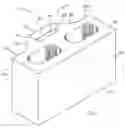
FIG. 1 is an isometric view of a masonry block in accordance with the present invention;
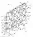
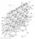
FIG. 2 is a rear isometric view retaining wall constructed of masonry blocks as shown in FIG. 1; and
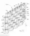
FIG. 3 is a rear isometric view of the retaining wall of FIG. 2 including a plurality of soil stabilising members located therewithin.
DESCRIPTION OF PREFERRED EMBODIMENTS
Referring to the Figures, there is shown a masonry block 10 having a substantially planar front face 12 and a rear face 14.
The rear face 14 has a back wall 16 substantially parallel to the front face 12, and an extension portion 18 extending outwardly from the back wall 16. The extension portion 18 in the embodiment of the drawings is trapezoid in shape, with an outermost face 20 which is substantially parallel to the front face 12, and two angled side faces 22 which taper from the back wall 16. The back wall 16 is thus divided into two substantially equal portions 16a and 16b, each of which are about two-thirds the width of the outermost face 10.
A substantially rectangular channel 24 passes through the extension portion 18 from a top face 26 of the block 10 to a bottom face 28. The channel 24 is substantially parallel to, and of approximately equal length to, the outermost face 20. The channel 24 is entirely contained within the extension portion 18, and is thus outside a plane determined by the back wall 16. The channel 24 has an openings at either end, with an upper opening 30 at the top face 26 and a lower opening (not shown) at the bottom face 28.
The portion of the block between the side walls 22 and the channel 24 is a shear-supporting portion 25.
In use, a retaining wall 40 as shown in FIG. 2 is constructed from a plurality of masonry blocks 10. The wall is constructed by laying the masonry blocks 10 in a plurality of courses 42. The blocks are layed such that the front faces 12 of the blocks 10 are substantially co-planar, as are the back walls 16. The back walls 16 combine to form a rear face 44 of the retaining wall 40.
Each course 42 is offset from an adjacent course 42 by 50%. In this way the extension portion 18 of a first block 10a in a first course 42a is adjacent a portion 16a of the back wall 16 of an adjacent second block 10b, and adjacent a portion 16b of the back wall 16 of an adjacent third block 10c, the second and third blocks 10b, 10c being in a second course 42b.
It will thus be apparent that the lower opening of the channel 24 of the first block 10a locates outside the back wall 16 of the adjacent blocks 10b, 10c, and is thus accessible even after subsequent courses 42 have been laid.
Once the retaining wall has been constructed as shown in FIG. 2, it is possible to introduce soil reinforcing members in the forms of strips 46 of geo-grid material into the retaining wall. In a preferred deployment of such strips, an inner portion 48 of a strip 46 is passed through the channels 24 of two parallel blocks 10a, 10d, the parallel blocks being in first and third courses 42a, 42c separated by a second course 42b. The strip 46 has two outer portions 50 extending from the upper opening 30 of the first block 10a and the lower opening of the fourth block 10d.
Preferably, strips 46 of geo-grid material are arrayed through the retaining wall 40 as shown in FIG. 3.
In an alternative deployment, strips 46 can be passed through a single block 10.
The outer portions 50 of the strips 46 are moved away from the rear face 44 of the retaining wall 40 as shown in FIG. 3. The rear face 44 can then be filled against with filling material such as soil, the strips 46 acting to both stabilise the soil and strengthen the wall.
It will be appreciated that the shear supporting portion 25 of the blocks 10 must be sufficiently strong to withstand shear forces introduced through the strips 46 when the retaining wall 40 is in use. It will also be appreciated that the channel is sized so as to allow the strip to pass within without restriction. In particular, the width of the channel is larger than that of the reinforcing member.
Modifications and variations as would be apparent to a skilled addressee are deemed to be within the scope of the present invention.
Claims
1. A masonry block having a front face and a rear face, characterised in that the rear face includes a back wall and an extension portion extending outwardly therefrom, the extension portion including a channel passing therethrough, the channel having openings at either end thereof, wherein, in use, when the extension portion of a first block in a first course is located adjacent the back wall of at least one adjacent second block in an adjacent second course, the front faces of the first and second blocks being substantially co-planar, a channel opening of the first block locates adjacent to, and outside of, the back wall of the second block, and whereby a portion of a soil restraining member may be restrained within the channel.
2. A masonry block as claimed in claim 1, characterised in that the channel is substantially parallel to the front face.
3. A masonry block as claimed in claim 1 or claim 2, characterised in that the extension portion is located substantially centrally of the rear face.
4. A masonry block as claimed in claim 3, characterised in that the extension portion has an outermost face substantially parallel to the front face.
5. A masonry block as claimed in claim 4, wherein the extension portion divides the real wall into two portions, each of which are about two thirds the width of the outermost face.
6. A masonry block as claimed in any preceding claim, characterised in that the channel is substantially rectangular.
7. A method of construction of a retaining wall, the method characterised by including the steps of laying courses of masonry blocks to form a wall having a rear face, at least one of the masonry blocks having an extension portion which extends beyond the rear face, the extension portion having a channel passing therethrough; passing a portion of a soil stabilising member through the channel to be retained thereby; moving an outer portion of the soil stabilising member away from the rear face; and filling against the rear wall face with filling material to cover the outer portion of the soil stabilising member.
8. A method of construction of a retaining wall as claimed in claim 7, characterised in that the soil stabilising member has upper and lower outer portions which are moved away from the rear face.
9. A method of construction of a retaining wall as claimed in claim 7 or claim 8, characterised in that the soil stabilising member is passed through the channel of at least two masonry blocks.
10. A method of construction of a retaining wall as claimed in claim 9, characterised in that the two masonry blocks are in two courses, the two courses being separated by at least one course.
Images & Drawings included:
Sources:
- United States Patent and Trademark Office - verify current appl. status at the USPTO↗
Similar patent applications:
- » 20160102453
SELF-REINFORCED MASONRY BLOCKS, WALLS MADE FROM SELF-REINFORCED MASONRY BLOCKS, AND METHOD FOR MAKING SELF-REINFORCED MASONRY BLOCKS - » 20130247497
Self-reinforced masonry blocks, walls made from self-reinforced masonry blocks, and method for making self-reinforced masonry blocks - » 20170254068
SELF-REINFORCED MASONRY BLOCKS, WALLS MADE FROM SELF-REINFORCED MASONRY BLOCKS, AND METHOD FOR MAKING SELF-REINFORCED MASONRY BLOCKS - » 20110133357
MASONRY BLOCKS AND MASONRY BLOCK ASSEMBLIES HAVING MOLDED UTILITY OPENINGS - » 20060185309
Masonry blocks and masonry block assemblies having molded utility openings - » 20060191231
Masonry blocks and method of making masonry blocks having overlapping faces - » 20110185673
PRECISION GROUND CONCRETE MASONRY BLOCKS AND SYSTEM AND METHOD FOR THE HIGH-SPEED APPLICATION OF MORTAR/GROUT TO PRECISION GROUND CONCRETE MASONRY BLOCKS AND SELF-LEVELING INSTALLATION OF CONCRETE MASONRY SYSTEMS - » 20120114850
PRECISION GROUND CONCRETE MASONRY BLOCKS AND SYSTEM AND METHOD FOR THE HIGH-SPEED APPLICATION OF MORTAR/GROUT TO PRECISION GROUND CONCRETE MASONRY BLOCKS AND SELF-LEVELING INSTALLATION OF CONCRETE MASONRY SYSTEMS - » 20090321991
MOLD FOR MAKING A MASONRY BLOCK AND METHOD FOR MAKING A MASONRY BLOCK - » 20050121830
Masonry blocks and method and system of making masonry blocks
Recent applications in this class:
- » 20220325494 2022-10-13
Catenary panel retaining wall - » 20220205211 2022-06-30
SYSTEMATIC PROTECTING AND UTILIZING METHOD FOR HILL RESOURCES - » 20210189680 2021-06-24
Method of manufacturing a facing element for a reinforced soil structure - » 20210062452 2021-03-04
Culvert system with flexible toe wall - » 20190242088 2019-08-08
Strip-type reinforcing material and reinforcing material assembly comprising same - » 20180094398 2018-04-05
Retaining wall - » 20170130417 2017-05-11
Edge protection safety bund system - » 20160326711 2016-11-10
Retaining wall - » 20150197912 2015-07-16
Retaining wall kit having interconnecting units - » 20150159339 2015-06-11
Retaining wall