Customizable Extruded Bottom Fence Rail
US20080142771A1
2008-06-19
11/934,332
2007-11-02
Abstract:
A customizable extruded bottom rail for a fence having a topside that is machine customizable to receive a plurality of stanchions taken from the group of picket, post, pole rod, bar, shaft, bar, and lath and supported on a substantially co-planar platform interiorly extending the length of the rail spaced apart from the topside separating the interior cavity into a stanchion supporting portion and a structurally reinforced portion with the structurally reinforced portion having a metallic stiffener positioned within a stiffener compartment having a plurality of braces extending between the rail's interior walls and the stiffener compartment walls that are situated for continued structural integrity of the product and continued continuity of the rail having the stiffener serving as brace anchor and deterring deformation of the fence rail of the instant invention from exterior forces.
Interested in similar patents?
Get notified when new applications in this technology area are published.
Classification:
E04H17/1439 » CPC main
Fencing, e.g. fences, enclosures, corrals; Fences constructed of rigid elements, e.g. with additional wire fillings or with posts; Post-and-rail fences, e.g. without vertical cross-members with vertical cross-members; Picket fences with separate pickets going through the horizontal members
E04F11/1853 » CPC further
Stairways, ramps, or like structures ; Balustrades; Handrails; Balustrades; Handrails; Balustrades; Filling panels, e.g. concrete, sheet metal panels Glass panels
E04F2011/1821 » CPC further
Stairways, ramps, or like structures ; Balustrades; Handrails; Balustrades; Handrails; Balustrades; Connections therefor between balustrade posts and horizontal or sloping balustrade members between balustrade posts and handrails
E04F2011/1889 » CPC further
Stairways, ramps, or like structures ; Balustrades; Handrails; Balustrades; Handrails; Handrails or balusters characterized by the use of specific materials mainly of metal
E04H17/14 IPC
Fencing, e.g. fences, enclosures, corrals Fences constructed of rigid elements, e.g. with additional wire fillings or with posts
Description
RELATED APPLICATIONS
This application is subject to U.S. provisional application Ser. No. 60/864032 filed 02 Nov. 2006.
BACKGROUND OF THE INVENTION
1. Field of the Invention
The present invention relates generally to fences and, more specifically, to an extruded cutomizable bottom rail for a fence having a topside that is machine customizable to receive a plurality of stanchions taken from the group of picket, post, pole rod, bar, shaft, bar, and lath and supported on a substantially co-planar platform interiorly extending the length of the rail spaced apart from the topside separating the interior cavity into a stanchion supporting portion and a structurally reinforced portion.
Within the structurally reinforced portion is a metallic stiffener positioned within a stiffener compartment having a plurality of braces extending between the rail's interior walls and the stiffener compartment walls that are situated for continued structural integrity of the product and continued continuity of the rail having the stiffener serving as brace anchor and deterring deformation of the fence rail of the instant invention from exterior forces.
The stiffener once positioned within the compartment may be fixed in location by forming a tab through pressure applied against a portion of the compartment wall sufficient to angularity bend said portion, relative to its longitudinal orientation, including the metallic stiffener and opposing compartment wall preventing movement therefrom.
2. Description of the Prior Art
There are other fences designed for modular assembly. While these fences may be suitable for the purposes for which they were designed, they would not be as suitable for the purposes of the present invention, as hereinafter described.
Therefore, it is felt that a need exist for a customizable fence bottom rail having the aforementioned properties.
SUMMARY OF THE PRESENT INVENTION
A primary object of the present invention is to provide an extruded bottom fence rail that is customizable for a desired fence style.
Another object of the present invention is to provide a customizable fence rail having a top surface and bottom surface with conjoined walls extending therebetween forming an interior cavity.
Yet another object of the present invention is to provide a customizable fence rail having an interior longitudinal wall formed within the top section of the interior cavity providing a slat/picket support portion and a lower structural reinforcement portion.
Still yet another object of the present invention is to provide a customizable fence rail wherein said slat/picket portion is customizable through machining at least one aperture of appropriate shape to receive a predetermined slat/picket with the internal longitudinal wall serving as support for said slat/picket.
Another object of the present invention is to provide a customizable fence rail where the aforementioned aperture has a peripheral rim that serves to reinforce the slat/picket from lateral displacement.
Yet another object of the present invention is to provide a customizable fence rail where the aforementioned structural reinforcement portion is primarily comprised of an elliptically shaped channel spanning the length of the fence rail conjoinedly extending from the interior base surface having a plurality of subtended braces.
Still yet another object of the present invention is to provide a customizable fence rail where the subtended braces extend approximately from the top, center and bottom exterior elliptical walls to the interior housing surfaces.
Another object of the present invention is to provide a customizable fence rail having a metal stiffener that is inserted into said elliptically shaped channel to preventing bowing of the fence rail under lateral forces.
Yet another object of the present invention is to provide a customizable fence rail having a metal stiffener that is anchored within said elliptical channel by punching through the elliptical wall, metal stiffener and opposing elliptical wall forming a tab that lockingly fastens the metal fastener to the elliptical channel.
Additional objects of the present invention will appear as the description proceeds.
The present invention overcomes the shortcomings of the prior art by providing an cutomizable extruded bottom rail for a fence having a topside that is machine customizable to receive a plurality of stanchions taken from the group of picket, post, pole rod, bar, shaft, bar, and lath and supported on a substantially co-planar platform interiorly extending the length of the rail spaced apart from the topside separating the interior cavity into a stanchion supporting portion and a structurally reinforced portion with the structurally reinforced portion having a metallic stiffener positioned within a stiffener compartment with a plurality of braces extending between the rail's interior walls and the stiffener compartment walls that are situated for continued structural integrity of the product and continued continuity of the rail having the stiffener serving as brace anchor and deterring deformation of the fence rail of the instant invention from exterior forces.
The stiffener once positioned within the compartment may be fixed in location by forming a tab through pressure applied against a portion of the compartment wall sufficient to angularly bend said portion, relative to its longitudinal orientation, including the metallic stiffener and opposing compartment wall preventing movement therefrom.
The foregoing and other objects and advantages will appear from the description to follow. In the description reference is made to the accompanying drawings, which forms a part hereof, and in which is shown by way of illustration specific embodiments in which the invention may be practiced. These embodiments will be described in sufficient detail to enable those skilled in the art to practice the invention, and it is to be understood that other embodiments may be utilized and that structural changes may be made without departing from the scope of the invention. In the accompanying drawings, like reference characters designate the same or similar parts throughout the several views.
The following detailed description is, therefore, not to be taken in a limiting sense, and the scope of the present invention is best defined by the appended claims.
BRIEF DESCRIPTION OF THE DRAWING FIGURES
In order that the invention may be more fully understood, it will now be described, by way of example, with reference to the accompanying drawing in which:
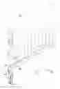
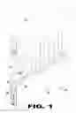
FIG. 1 is an illustrative view of the extruded customizable fence rail of the present invention in use;
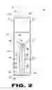
FIG. 2 is a sectional view of the extruded customizable fence rail of the present invention;
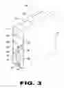
FIG. 3 is a perspective view of the customizable extruded fence rail of the present invention;
FIG. 4 is an illustrative view of the rigid stiffener aligned for insertion into the stiffener compartment;
FIG. 5 is a perspective view of the rigid stiffener being inserted the stiffener compartment; and
FIG. 6 is a sectional view of the customizable extruded bottom fence rail of the present invention.
DESCRIPTION OF THE REFERENCED NUMERALS
Turning now descriptively to the drawings, in which similar reference characters denote similar elements throughout the several views, the figures illustrate the Customizable Extruded Fence Rail of the present invention. With regard to the reference numerals used, the following numbering is used throughout the various drawing figures.
10. Extruded Customizable Fence Rail of the present invention
12. fence pickets
14. fence top rail
16. fence rail wall
17. interior wall surface
18. fence rail cutomizable top surface
20. fence rail base
22. base interior surface
24. routed aperture
26. routed aperture rim
28. picket support wall
30. stiffener compartment
32. stiffener compartment top surface
34. stiffener compartment walls
36. stiffener wall exterior surface
38. stiffener compartment top surface brace
40. stiffener compartment wall center brace
42. stiffener compartment wall bottom brace
44. metal stiffener
46. punched tab stiffener retainer
DETAILED DESCRIPTION OF THE PREFERRED EMBODIMENT
The following discussion describes in detail one embodiment of the invention (and several variations of that embodiment). This discussion should not be construed, however, as limiting the invention to those particular embodiments, practitioners skilled in the art will recognize numerous other embodiments as well. For definition of the complete scope of the invention, the reader is directed to appended claims.
Referring to FIG. 1, shown is the customizable extruded bottom fence rail of the present invention in use with fence pickets 12 and top rail 14. The bottom fence rail 10 has top routable surface 18 wherein the footprint of picket 12 is routed out of top surface 18 creating aperture 24 having aperture rim 26 which substantially engages the exterior surface of picket 18 which is supported on picket support surface 28.
FIG. 2 is a sectional end view of the customizable extruded bottom fence rail of the present invention. As illustrated, the bottom fence rail 10 of the present invention has a housing comprised of rail base 20 having conjoined spaced apart walls 16 vertically extending therefrom to customizable top surface 18 which is selectively routed creating picket aperture 24 to accommodate the desired picket 12 and supported on picket support wall 28. Structural reinforcement members are contained with the rail housing with the main reinforcement member comprising an elliptically shaped stiffener compartment 30 having top surface 32 with the compartment running the length of the rail housing for placement therein of a metal stiffener 44 that once positioned within compartment 30 allows for punching through stiffener compartment wall 34 from wall exterior surface 36 through stiffener 44 and opposing compartment wall 34 therein forming tab 46 lockingly engaging stiffener 44 between compartment walls 34. Structural supports are additionally provided between stiffener compartment 30 and housing wall interior surface 17 comprising top end braces 38 extending from compartment top surface 32 to interior wall 17, center braces 40 extending from exterior surface 36 of wall 34 to interior wall surface 17 and bottom braces 42 extending from exterior surface 36 of wall 34 to interior base surface 22 of base wall 20.
FIG. 3 is a perspective view of the customizable extruded fence rail of the present invention. Shown is the compartmentalized customizable bottom rail 10 having picket support wall 28 forming a top most picket support portion and a bottom structural reinforcement portion contained within rail housing which is comprised of rail base 20 with depending spaced apart walls 16 vertically extending therefrom to customizable top surface 18 which is selectively routed for a desired picket aperture shape 24 to accommodate picket 12 supported on picket support wall 28. Structural reinforcement members are comprised of an elliptically shaped stiffener compartment 30 having braces extending between stiffener compartment 30 exterior walls and housing interior wall surfaces comprising top end braces 38 extending from compartment top surface 32 to interior wall 17, center braces 40 extending from exterior surface 36 of wall 34 to interior wall surface 17 and bottom braces 42 extending from exterior surface 36 of wall 34 to interior base surface 22 of base wall 20.
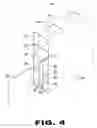
FIG. 4 is an illustrative view of the rigid stiffener aligned for insertion into the stiffener compartment. As aforementioned, the customizable bottom fence rail 10 has a housing comprised of rail base 20 having conjoined spaced apart walls 16 vertically extending therefrom to customizable top surface 18 which is selectively routable to create picket aperture 24 to accommodate the desired picket 12 which is inserted therein and supported on picket support wall 28. Structural reinforcement members are contained within the rail housing with the main reinforcement member comprising an elliptically shaped stiffener compartment 30 having braces extending between stiffener compartment 30 and housing wall interior surface 17 comprising top end braces 38 extending from compartment top surface 32 to interior wall 17, center braces 40 extending from exterior surface 36 of compartment wall 34 to interior wall surface 17 and bottom braces 42 extending from exterior surface 36 of wall 34 to interior base surface 22 of base wall 20.
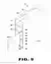
FIG. 5 is a perspective view of the rigid stiffener being inserted the stiffener compartment. Structural reinforcement members are contained within the rail housing with the main reinforcement member comprising an elliptically shaped stiffener compartment 30 having top surface 32 with the compartment running the length of the rail housing for placement therein of a metal stiffener 44 that once positioned within compartment 30 allows for punching through stiffener compartment wall 34 from wall exterior surface 36 through stiffener 44 and opposing compartment wall 34 therein forming tab 46 lockingly engaging stiffener 44 between compartment walls 34. Structural supports are additionally provided between stiffener compartment 30 and housing wall interior surface 17 comprising top end braces 38 extending from compartment top surface 32 to interior wall 17, center braces 40 extending from exterior surface 36 of wall 34 to interior wall surface 17 and bottom braces 42 extending from exterior surface 36 of compartment wall 34 to interior base surface 22 of base wall 20.
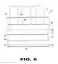
FIG. 6 is a sectional view of the customizable extruded bottom fence rail of the present invention. Depicted is the customizable bottom rail having customizable top surface 18 with routed apertures 24 with peripheral rim 26 used in conjunction with picket support wall 28 to contain and support the lower portion of picket 12. Also shown is stiffener compartment 30 brace 38 extending from compartment top surface 32, Brace 40 extending from compartment wall 34 and bottom brace 42 fastened between compartment wall 34 and housing base 20 interior wall surface 22.
The foregoing is illustrative of the present invention and is not to be construed as limiting thereof. Although exemplary embodiments of this invention have been described, those skilled in the art will readily appreciate that many modifications are possible in the exemplary embodiments without materially departing from the novel teachings and advantages of this invention. Accordingly, all such modifications are intended to be included within the scope of this invention as defined in the claims. The invention is defined by the claims, with equivalents of the claims to be included therein.
Claims
What is claimed is new and desired to be protected by Letters Patent is set forth in the appended claims:1. A customizable extruded bottom fence rail comprising:
a) a housing having a top side, bottom side with spaced apart walls therebetween;
b) a longitudinal wall dividing the housing interior surface into a picket support portion and a structural support portion; and
c) a structural support portion stiffener compartment extending the length of the fence bottom rail for insertion therein of a rigid stiffening member.
2. The customizable extruded bottom fence rail as recited in claim 1, wherein the rigid stiffening member is metal.
3. The customizable extruded bottom fence rail as recited in claim 2, wherein the stiffener compartment walls and metal stiffener have a portion transversely forming a tab fixing the metal stiffener location.
4. The customizable extruded bottom fence rail as recited in claim 1, wherein the topside planar surface provides for machining at least one aperture therein for insertion therethrough of a stanchion that is supported upon said longitudinal wall.
5. The customizable extruded bottom fence rail as recited in claim 4 wherein said stanchion is taken from the group of sheet, panel, board, plank, slat, and lath.
6. The customizable extruded bottom fence rail as recited in claim 1 wherein the stiffening compartment has a substantially elliptical shape fixedly positioned with a plurality of braces;
7. The customizable extruded bottom fence rail as recited in claim 6 wherein said braces extend between the stiffener compartment exterior wall to the housing interior wall.
8. The customizable extruded bottom fence rail as recited in claim 7, wherein the braces comprise a pair of stiffener compartment top portion braces, a pair of central portion braces and a pair of bottom portion braces.
Images & Drawings included:
Sources:
- United States Patent and Trademark Office - verify current appl. status at the USPTO↗
Recent applications in this class:
- » 20250146324 2025-05-08
USER ASSEMBLABLE PICKET RAIL PANEL - » 20240352764 2024-10-24
FENCE PANEL - » 20230366236 2023-11-16
User assemblable picket rail panel - » 20230243179 2023-08-03
ADJUSTABLE RACKING BARRIER SYSTEM - » 20230123821 2023-04-20
FENCE - » 20230061630 2023-03-02
SECURITY FENCE - » 20230058344 2023-02-23
Fence construction - » 20220316232 2022-10-06
Grid structure - » 20220220764 2022-07-14
Modular railing suitable for variable installation slopes - » 20220186520 2022-06-16
Bollard Fence