Modular Reader Portal
US20080143221A1
2008-06-19
11/949,640
2007-12-03
Abstract:
A modular reader portal and method of forming the same. In one embodiment, the modular reader portal includes first and second vertical stanchions including a telescopic segment configured to adjust a height thereof. The modular reader portal also includes a horizontal stanchion including a telescopic segment to provide an adjustable horizontal crossbar between the first and second vertical stanchions. The modular reader portal further includes a reader attached to one of the first and second vertical stanchions and the horizontal stanchion configured to read an identification tag located on a product passing near the modular reader portal.
Interested in similar patents?
Get notified when new applications in this technology area are published.
Classification:
H01Q1/2216 » CPC main
Details of, or arrangements associated with, antennas; Supports; Mounting means by structural association with other equipment or articles associated with components used in interrogation type services, i.e. in systems for information exchange between an interrogator/reader and a tag/transponder, e.g. in Radio Frequency Identification [RFID] systems used in interrogator/reader equipment
A47B81/06 IPC
Cabinets or racks specially adapted for other particular purposes, e.g. for storing guns or skis Furniture aspects of radio, television, gramophone, or record cabinets
Description
This application claims the benefit of U.S. Provisional Application No. 60/872,165, entitled “RFID Systems,” filed on Dec. 1, 2006, which application is incorporated herein by reference.
TECHNICAL FIELD
The present invention is directed, in general, to reader systems and, in particular, to a modular reader portal and method of forming the same.
BACKGROUND
While the core technologies that support radio frequency identification (“RFID”) systems have been around for some time, the applications that drive the use thereof have been slow to market. The aforementioned trend has been turning in an impressive fashion as the size and cost of the RFID tags has decreased and the sensitivity of RFID readers has increased. Moreover, the market forces, especially with respect to the supply chain in the retail industry, are pulling the RFID technologies into the mainstream and literally onto the shelves.
With respect to the supply chain, portals (e.g., RFID portals) including readers (e.g., RFID readers) are employed to read identification tags (e.g., RFID tags) on boxes and the like as products move from one location to another within the supply chain. During RFID deployments (e.g., hardware installations), it is difficult to properly determine portal configurations to install a fixed RFID portal. For instance, varying sizes are required portal-to-portal and customer-to-customer. Install locations are often changed at the last minute (e.g., customer requirements change), which can make even proper planning and design a challenge at the time of installation. Due to building constraints, the RFID portals may not be anchored to a wall (e.g, metal buildings may not provide sufficient structural support for a wall mount like a concrete wall). Dock leveler equipment may or may not be present (pit levelers may be cut into the floor of the facility), or there may be other obstructions that require some flexibility like dock seals, dock lamps, or trailer safety light panels.
There are other design flaws of typical RFID portals. For instance, cables are often exposed, which can be damaged or severed by material handling equipment. The assembly holes may be misaligned, or manufacturing defects may occur due to a lack of reference edges. This adds much time for proper assembly onsite and can result in rework time needing to be done onsite.
The manufacturing lead times on the hardware portals can vary from two to six weeks depending on the workload at the manufacturer sites as well as the design of the portal that is specified. These lead times can cause critical installation schedule problems if the RFID portal designs are not pre-built. An additional challenge with custom portals is that they are more expensive to produce.
Accordingly, what is needed in the art is a modular reader system including a portal employable in several configurations, preferably using standardized components, that overcomes the deficiencies in the prior art.
SUMMARY OF THE INVENTION
These and other problems are generally solved or circumvented, and technical advantages are generally achieved, by advantageous embodiments of the present invention that include a modular reader portal and method of forming the same. In one embodiment, the modular reader portal includes first and second vertical stanchions including a telescopic segment configured to adjust a height thereof. The modular reader portal also includes a horizontal stanchion including a telescopic segment to provide an adjustable horizontal crossbar between the first and second vertical stanchions. The modular reader portal further includes a reader attached to one of the first and second vertical stanchions and the horizontal stanchion configured to read an identification tag located on a product passing near the modular reader portal.
In another aspect, the present invention provides a method of forming a modular reader portal. The method includes forming first and second vertical stanchions with a telescopic segment configured to adjust a height thereof. The method also includes forming a horizontal stanchion with a telescopic segment to provide an adjustable horizontal crossbar between the first and second vertical stanchions. The method further includes attaching a reader to one of the first and second vertical stanchions and the horizontal stanchion configured to read an identification tag located on a product passing near the modular reader portal.
The foregoing has outlined rather broadly the features and technical advantages of the present invention in order that the detailed description of the invention that follows may be better understood. Additional features and advantages of the invention will be described hereinafter which form the subject of the claims of the invention. It should be appreciated by those skilled in the art that the conception and specific embodiment disclosed may be readily utilized as a basis for modifying or designing other structures or processes for carrying out the same purposes of the present invention. It should also be realized by those skilled in the art that such equivalent constructions do not depart from the spirit and scope of the invention as set forth in the appended claims.
BRIEF DESCRIPTION OF THE DRAWINGS
For a more complete understanding of the present invention, and the advantages thereof, reference is now made to the following descriptions taken in conjunction with the accompanying drawings, in which:
FIG. 1 illustrates a system level diagram of an embodiment of an RFID system constructed according to the principles of the present invention;
FIG. 2 illustrates a block diagram of an embodiment of an RFID tag constructed according to the principles of the present invention; and
FIGS. 3 to 7 illustrate diagrams of portions of modular reader portals constructed according to the principles of the present invention.
DETAILED DESCRIPTION OF ILLUSTRATIVE EMBODIMENTS
The making and using of the presently preferred embodiments are discussed in detail below. It should be appreciated, however, that the present invention provides many applicable inventive concepts that can be embodied in a wide variety of specific contexts. The specific embodiments discussed are merely illustrative of specific ways to make and use the invention, and do not limit the scope of the invention. Unless otherwise provided, like designators for devices employed in different embodiments illustrated and described herein do not necessarily mean that the similarly designated devices are constructed in the same manner or operate in the same way. The present invention will be described with respect to an exemplary embodiment in a specific context, namely, an RFID system including an RFID portal that is not only rugged, but is also flexibly used in a number of install configurations to ease assembly and installation as well as reduce costs and manufacturing lead times. While the exemplary embodiments are described with respect to an RFID system and portal, those skilled in the art should understand that the principles of the present invention are applicable to any reader system and modular reader portal including, without limitation, bar code readers and optical readers.
In an exemplary embodiment, the RFID portal is developed for speed of assembly and ease of installation while retaining critical strength and lighter weight, lowering costs. For visual safety, the RFID portal may be powder coated or painted a safety color (e.g., yellow). The RFID portal components are preferably standardized for flexible use in multiple scenarios. An embodiment of the RFID portal is set forth below. Those skilled in the art, however, understand that the RFID system may employ other modular portal configurations and still fall within the broad scope of the present invention.
Referring initially to FIG. 1, illustrated is a system level diagram of an embodiment of an RFID system constructed according to the principles of the present invention. The RFID system includes a server 110, a computer system 120, and an RFID portal 125 including an RFID reader 130 located on a backplane mounting plate 135 with antennas (designated 140). The computer system 120 (in connection with the server 110) directs the RFID reader 130 to read RFID tag(s) 150 located on a product or host material 160. The RFID portal 125 includes first and second vertical stanchions 170, 175 formed from telescopic segments configured to adjust a height thereof. The RFID portal 125 also includes a horizontal stanchion 180 formed from telescopic segments to form an adjustable horizontal crossbar between the first and second vertical stanchions 170, 175. Each of the vertical stanchions 170, 175 include mount plate footings 190 at a base thereof.
While a single product 160 is illustrated herein, those skilled in the art should understand that the product conceptually may also represent multiple products. In addition, the communication links between respective systems in the RFID system may be wired or wireless communication paths to facilitate the transmission of information therebetween. For a better understanding of communication theory, see the following references “Introduction to Spread Spectrum Communications,” by Roger L. Peterson, et al., Prentice Hall, Inc. (1995), “Modern Communications and Spread Spectrum,” by George R. Cooper, et al., McGraw-Hill Books, Inc. (1986), “An Introduction to Statistical Communication Theory,” by John B. Thomas, published by John Wiley & Sons, Ltd. (1995), “Wireless Communications, Principles and Practice,” by Theodore S. Rappaport, published by Prentice Hall, Inc. (1996), “The Comprehensive Guide to Wireless Technologies,” by Lawrence Harte, et al., published by APDG Publishing (1998), “Introduction to Wireless Local Loop,” by William Webb, published by Artech Home Publishers (1998), and “The Mobile Communications Handbook,” by Jerry D. Gibson, published by CRC Press in cooperation with IEEE Press (1996), all of which are incorporated herein by reference.
Turning now to FIG. 2, illustrated is a block diagram of an embodiment of an RFID tag constructed according to the principles of the present invention. The RFID tag is affixed or applied to a host material (e.g., a host material including a metal surface or a metal object) 210 and includes an integrated circuit 220 (including memory and a processor) located or embodied in a carrier 230 coupled to an antenna 240. An adhesive 250 is coupled to (e.g., located above and proximate) the carrier 230 and a strain relief member 260 is located above and proximate (e.g., bonded) to the adhesive 250. More particularly, the strain relief member 260 is coupled to the adhesive 250 on a surface opposite the integrated circuit 220 and the carrier 230. In the illustrated embodiment, the adhesive 250 and the strain relief member 260 cover a surface area of the integrated circuit 220 and the carrier 230. The strain relief member 260 provides strain relief for the integrated circuit 220 when the RFID tag is subject to mechanical stress such as compressive or expansive forces. Additionally, the strain relief member 260 may be formed from a temperature resistive material (e.g., a heat resistive material). The RFID tag is encapsulated by an encapsulant 270, which is coupled to and provides an offset for the RFID tag in relation to the host material 210.
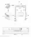
Turning now to FIGS. 3 to 7, illustrated are diagrams of portions of modular reader portals constructed according to the principles of the present invention. More specifically, FIG. 3 illustrates an exploded isometric view of portions of an embodiment of a modular reader portal. FIG. 4 illustrates a view of an embodiment of an installation footing for a modular reader portal. FIG. 5 illustrates a view of an embodiment of portions of a modular reader portal demonstrating exemplary mounting options.
TABLE I below provides a sample bill of materials for the RFID portal introduced above.
| TABLE I | ||||
| REF No. | REFERENCE | SIZE | DESCRIPTION | QTY |
| 1 | Foot | 6 × 6 | 12 GA HR | 2 |
| 2 | Secondary | 4 × 11.135 | 12 GA HR | 2 |
| Mount Coupling | ||||
| 3 | Sleeve Footer | 9.772 × 48 | 12 GA HR | 2 |
| Stanchion | ||||
| 4 | Telescopic | 8.224 × 30 | 12 GA HR | 2 |
| Segment | ||||
| 5 | Sleeve Segment | 9.772 × 48 | 12 GA HR | 2 |
| 6 | Telescopic | 8.224 × 35.655 | 12 GA HR | 2 |
| Segment Elbow | ||||
| (vertical portion) | ||||
| 7 | Telescopic | 8.224 × 35.865 | 12 GA HR | 2 |
| Segment Elbow | ||||
| (horizontal | ||||
| portion) | ||||
| 8 | Sleeve Segment | 9.772 × 29.865 | 12 GA HR | 2 |
| 9 | Backplane | 12 × 12 | 12 GA HR | 1 |
| Mounting Plate | ||||
| 10 | Telescopic | 8.224 × 40 | 12 GA HR | 1 |
| Segment | ||||
| 11 | Antenna Mount | 4 × 11.443 | 12 GA HR | 16 |
| Coupling | ||||
| 12 | Antenna Mount | 1.5 × 1.805 | 12 GA HR | 40 |
| Coupling Bolt | ||||
| Plate | ||||
| 13 | Antenna Mount | 1.5 × 5.5 | 12 GA HR | 16 |
| Coupling Flange | ||||
| Tab | ||||
| 14 | Antenna Bolt | 2.5 × 3.25 | 12 GA HR | 16 |
| Mounting Plate | ||||
| 15 | Reader | 10.375 × 16.129 | 12 GA HR | 2 |
| Enclosure | ||||
| 17 | Secondary | 2.725 × 2.79 | 12 GA HR | 2 |
| Mounting Flange | ||||
| 18 | Sleeve Segment | 9.772 × 24.298 | 12 GA HR | 2 |
| 19 | Telescopic | 8.224 × 24.298 | 12 GA HR | 2 |
| Segment | ||||
| 20 | Secondary | 2.364 × 2.442 | 12 GA HR | 2 |
| Mounting Flange | ||||
| 21 | Wall Mount Foot | 6 × 6 | 12 GA HR | 2 |
| Plate | ||||
| 22 | Assembly Bolt | ⅜16 × 1.0 | 60 | |
| HEX HESD | ||||
| BOLT | ||||
| 23 | Assembly Nut | ⅜16 HEX | 60 | |
| NUT | ||||
| 24 | Assembly | ⅜ FLAT | 120 | |
| Washer | WASHER | |||
| 25 | Assembly Lock | ⅜ LOCK | 60 | |
| Washer | WASHER | |||
The modular reader portal's design allows for adjustable dimensions in three dimensions (length, width, and height). The modular reader portal includes first and second vertical stanchions formed from, in part, sleeve footer stanchions 3, telescopic segments 4, sleeve segments 5 and telescopic segment elbows 6 configured to adjust a height thereof. The modular reader portal also includes a horizontal stanchion formed from, in part, telescopic segment elbows 7, sleeve segments 8 and telescopic segments 10 to form an adjustable horizontal crossbar between the first and second vertical stanchions. A reader is attached to the horizontal stanchion via a backplane mounting plate 9, enclosed by an enclosure 15, and is configured to read an identification tag located on a product passing near the reader portal. The mount plate footings can be placed in different locations and in different quantities based on the specific installation needs. The locations of these footings may be altered on the fly and can be performed on site with little assembly time impact.
A reader may be attached to a backplane mounting plate with universally predrilled holes to meet reader bolt hole requirements. Different manufacturers of readers make differently sized readers with nonstandard bolt patterns for mounting across the products. Also, as new readers come onto the market for use, those skilled in the art understand that the backplane mounting plate may be modified to accommodate any reader or other piece of hardware as needed. Another embodiment of this design could allow the reader to be mounted to a wall or another panel that is convenient for the installer, preferably without lift equipment.
A cover, such as a National Electrical Manufacturers Association (“NEMA”) enclosure, may be used to protect the reader from the environmental conditions while allowing an operator to observe the reader through the open sides. A specially designed cover may be used to prevent an opportunity for the antenna cables to become exposed, but those skilled in the art understand this characteristic of installation.
Turning now to FIGS. 6 and 7, illustrated are diagrams of an exemplary reader enclosure and backplane mounting plate for a modular reader portal according to the principles of the present invention. More specifically, FIGS. 6A, 6B, 6C, 6D and 6E illustrate a left side view, a top view, a right side view, a bottom view, and a front view, respectively, of the reader enclosure. Additionally, FIG. 7 illustrates a top view of the backplane mounting plate. Of course, the dimensions on the FIGUREs are provided for illustrative purposes only. The reader enclosure illustrated in FIG. 6 provides flexibility in mounting a variety of different components in the same enclosure. As deployment environments may vary, the reader enclosure is adaptable, as is the modular reader portal, to allow for operators to make component changes on site as needed. The backplane mounting plate illustrated in FIG. 7 allows for the reader enclosure of FIG. 6 to be easily mounted to the backplane, which is assembled to, for instance, a telescopic segment of a horizontal stanchion. The additional benefits for utilizing the reader enclosure are that it permits preassembly and testing prior to arrival on site to expedite the installation process for personnel. Those skilled in the art of modular reader portals understand that the reader enclosure is included as an example and additional embodiments of a reader mounting system for a modular reader portal are well within the broad scope of the present invention.
The readers often utilize external antennas that may be attached to the modular reader portal. Additionally as illustrated in FIG. 5, adjustable mounts (designated “AM”) may be used to allow for flexible locations in three dimensions/orientations. The adjustable mounts may also be used for mounting other reader hardware accessories such as a NEMA box for attaching a programmable logic controller (“PLC”) or an input/output (“IO”) device. Again, those skilled in the art understand that the mounts may be used in different ways to accommodate various designs.
Thus, a modular reader portal and method of forming the same has been introduced herein. In one embodiment, the modular reader portal includes first and second vertical stanchions including a sleeve footer stanchion, a sleeve segment, a telescopic segment and a telescopic segment elbow configured to adjust a height thereof. The modular reader portal also includes a mount plate footing at a base of the first and second vertical stanchions. The modular reader portal also includes a horizontal stanchion including a telescopic segment elbow, a telescopic segment and a sleeve segment to provide an adjustable horizontal crossbar between the first and second vertical stanchions. The modular reader portal further includes a reader (e.g., a radio frequency identification reader, a bar code reader and an optical reader) located on a backplane mounting plate and an antenna attached to one of the first and second vertical stanchions and the horizontal stanchion configured to read an identification tag located on a product passing near the modular reader portal. Additionally, the reader is directed to read the identification tag by a computer system. The reader is also enclosed in a reader enclosure. The modular reader portal still further includes adjustable mounts configured to mount the first and second vertical stanchions to one of a floor and a wall.
For a better understanding of RFID technologies, in general, see “RFID Handbook,”by Klaus Finkenzeller, published by John Wiley & Sons, Ltd., 2nd edition (2003), which is incorporated herein by reference. For a better understanding of RFID tags in compliance with the EPC, see “Technical Report 860 MHz-930 MHz Class I Radio Frequency Identification Tag Radio Frequency & Logical Communication Interface Specification Candidate Recommendation,” Version 1.0.1, November 2002, promulgated by the Auto-ID Center, Massachusetts Institute of Technology, 77 Massachusetts Avenue, Bldg 3-449, Cambridge Mass. 02139-4307, which is incorporated herein by reference. For a better understanding of conventional RFID readers, see the following RFID readers, namely, “MP9320 UHF Long-Range Reader,” provided by SAMSys Technologies, Inc. of Ontario, Canada, “MR-1824 Sentinel-Prox Medium Range Reader,” by Applied Wireless ID of Monsey, N.Y. (see also U.S. Pat. No. 5,594,384 entitled “Enhanced Peak Detector,” U.S. Pat. No. 6,377,176 entitled “Metal Compensated Radio Frequency Identification Reader,” U.S. Pat. No. 6,307,517 entitled “Metal Compensated Radio Frequency Identification Reader”), “2100 UAP Reader,” provided by Intermec Technologies Corporation of Everett, Wash. and “ALR-9780 Reader,” provided by Alien Technology Corporation of Morgan Hill, Calif., all of which are incorporated by reference.
Furthermore, for a better understanding of standards base work regarding RFID, see the EPCglobal standards and related publications, namely, EPCglobal release EPC Specification for Class 1 Gen 2 RFID Specification, December 2004, and a “Whitepaper: EPCglobal Class 1 Gen 2 RFID Specification,” published by Alien Technology Corporation, Morgan Hill, Calif. (2005). For a better understanding of RFID devices, see U.S. Pat. No. 6,853,087, entitled “Component and Antennae Assembly in Radio Frequency Identification Devices,” to Neuhaus, et al., issued Feb. 8, 2005. For related applications, see U.S. Patent Application Publication No. 2006/0212141, entitled “Radio Frequency Identification-Detect Ranking System and Method of Operating the Same,” Abraham, Jr., et al., published Sep. 21, 2006, U.S. Patent Application Publication No. 2006/0212164, entitled “Radio Frequency Identification Application System,” to Abraham, Jr., et al., published Sep. 21, 2006, U.S. Patent Application Publication No. 2007/0229284, entitled “Radio Frequency Identification Tag and Method of Forming the Same,” to Svalesen, et al., published Oct. 4, 2007, and U.S. patent application Ser. No. 11/876,978, entitled “Asset Including a Radio Frequency Identification Tag and Method of Forming the Same, to Svalesen, et al., filed Oct. 23, 2007. The aforementioned references, and all references herein, are incorporated herein by reference in their entirety.
Also, although the present invention and its advantages have been described in detail, it should be understood that various changes, substitutions and alterations can be made herein without departing from the spirit and scope of the invention as defined by the appended claims. For example, many of the materials and structures discussed above can be implemented in different materials and structures to advantageously form an RFID system as described herein.
Moreover, the scope of the present application is not intended to be limited to the particular embodiments of the process, machine, manufacture, composition of matter, means, methods and steps described in the specification. As one of ordinary skilled in the art will readily appreciate from the disclosure of the present invention, processes, machines, manufacture, compositions of matter, means, methods, or steps, presently existing or later to be developed, that perform substantially the same function or achieve substantially the same result as the corresponding embodiments described herein may be utilized according to the present invention. Accordingly, the appended claims are intended to include within their scope such processes, machines, manufacture, compositions of matter, means, methods, or steps.
Claims
What is claimed is:1. A modular reader portal, comprising:
first and second vertical stanchions including a telescopic segment configured to adjust a height thereof;
a horizontal stanchion including a telescopic segment to provide an adjustable horizontal crossbar between said first and second vertical stanchions; and
a reader attached to one of said first and second vertical stanchions and said horizontal stanchion configured to read an identification tag located on a product passing near said modular reader portal.
2. The modular reader portal as recited in claim 1 wherein said reader is selected from the group consisting of:
a radio frequency identification reader,
a bar code reader, and
an optical reader.
3. The modular reader portal as recited in claim 1 wherein said reader is coupled to an antenna attached to one of said first and second vertical stanchions and said horizontal stanchion.
4. The modular reader portal as recited in claim 1 wherein said reader is directed to read said identification tag by a computer system.
5. The modular reader portal as recited in claim 1 wherein said reader is located on a backplane mounting plate attached to one of said first and second vertical stanchions and said horizontal stanchion.
6. The modular reader portal as recited in claim 1 further comprising a mount plate footing at a base of said first and second vertical stanchions.
7. The modular reader portal as recited in claim 1 further comprising adjustable mounts configured to mount said first and second vertical stanchions to one of a floor and a wall.
8. The modular reader portal as recited in claim 1 wherein said reader is enclosed in a reader enclosure.
9. The modular reader portal as recited in claim 1 wherein said first and second vertical stanchions further include a sleeve footer stanchion, a sleeve segment and a telescopic segment elbow.
10. The modular reader portal as recited in claim 1 wherein said horizontal stanchion further includes a telescopic segment elbow and a sleeve segment.
11. A method of forming a modular reader portal, comprising:
forming first and second vertical stanchions with a telescopic segment configured to adjust a height thereof;
forming a horizontal stanchion with a telescopic segment to provide an adjustable horizontal crossbar between said first and second vertical stanchions; and
attaching a reader to one of said first and second vertical stanchions and said horizontal stanchion configured to read an identification tag located on a product passing near said modular reader portal.
12. The method as recited in claim 11 wherein said reader is selected from the group consisting of:
a radio frequency identification reader,
a bar code reader, and
an optical reader.
13. The method as recited in claim 11 further comprising attaching an antenna for said reader to one of said first and second vertical stanchions and said horizontal stanchion.
14. The method as recited in claim 11 wherein said reader is directed to read said identification tag by a computer system.
15. The method as recited in claim 11 further comprising attaching a backplane mounting plate to one of said first and second vertical stanchions and said horizontal stanchion, and wherein attaching said reader includes attaching said reader to said backplane mounting plate.
16. The method as recited in claim 11 further comprising forming a mount plate footing at a base of said first and second vertical stanchions.
17. The method as recited in claim 11 further comprising forming adjustable mounts configured to mount said first and second vertical stanchions to one of a floor and a wall.
18. The method as recited in claim 11 further comprising enclosing said reader in a reader enclosure.
19. The method as recited in claim 11 wherein forming said first and second vertical stanchions further includes forming said first and second vertical stanchions with a sleeve footer stanchion, a sleeve segment and a telescopic segment elbow.
20. The method as recited in claim 11 wherein forming said horizontal stanchion further includes forming said horizontal stanchion with a telescopic segment elbow and a sleeve segment.
Images & Drawings included:


Sources:
- United States Patent and Trademark Office - verify current appl. status at the USPTO↗
Recent applications in this class:
- » 20250030146 2025-01-23
RADIO FREQUENCY IDENTIFICATION (RFID) ANTENNA AND COMMUNICATION SYSTEM - » 20240396204 2024-11-28
RADIOFREQUENCY IDENTIFICATION EQUIPPED MEDICAL CABINET SYSTEMS AND METHODS OF ASSEMBLY AND USE THEREOF - » 20240372244 2024-11-07
ANTENNA FOR AN RFID READING DEVICE WITH POLARIZATION SWITCHING - » 20240291133 2024-08-29
Antenna Arrangement for RFID-Integrated Scanning Device - » 20240250407 2024-07-25
NFC READER WITH NFC ANTENNA AND WIRELESS CHARGING ANTENNA - » 20240113411 2024-04-04
RFID system - » 20240014541 2024-01-11
ELECTRONIC DEVICE - » 20230411824 2023-12-21
RADIO COMMUNICATION ANTENNA CONSISTING OF A PREVIOUSLY BENT RIGID METALLIC WIRE, SUPPORT STRUCTURE AND CORRESPONDING PAYMENT TERMINAL - » 20230198121 2023-06-22
Radiofrequency identification equipped medical cabinet systems and methods of assembly and use thereof - » 20230187811 2023-06-15
Dual-antenna, four-armed identification tag