Fuse assembly
US20080143471A1
2008-06-19
11/639,208
2006-12-15
Abstract:
The present invention relates to a fuse assembly, which includes a main body, two metal legs, a meltable rod having its both ends being connected by inner ends of the metal legs respectively, and a cover. A thin tin layer is connected tightly between the inner end of the metal leg and the rod without any space. The fuse assembly then obtains a perfect electrical connection. It cab be used on any electrical product with a high effective and stable function.
Interested in similar patents?
Get notified when new applications in this technology area are published.
Classification:
H01H85/0417 » CPC main
Protective devices in which the current flows through a part of fusible material and this current is interrupted by displacement of the fusible material when this current becomes excessive; Details; Fuses, i.e. expendable parts of the protective device, e.g. cartridges characterised by the type; Miniature fuses cartridge type with parallel side contacts
H01H85/143 » CPC further
Protective devices in which the current flows through a part of fusible material and this current is interrupted by displacement of the fusible material when this current becomes excessive; Details; Fuses, i.e. expendable parts of the protective device, e.g. cartridges; Component parts thereof Electrical contacts; Fastening fusible members to such contacts
H01H85/04 IPC
Protective devices in which the current flows through a part of fusible material and this current is interrupted by displacement of the fusible material when this current becomes excessive; Details Fuses, i.e. expendable parts of the protective device, e.g. cartridges
Description
FIELD OF THE INVENTION
The present invention relates to a fuse assembly, which provides an improved fuse structure to obtain a well connection between a meltable rod and inner connecting ends of metal legs.
BACKGROUND OF THE INVENTION
A conventional fuse of normal electrical products, as shown in FIG. 1 and 2, includes a main body (1), two metal legs (2), a meltable rod (3), and a cover (4). The metal leg (2) has its short inner end (21) connect with the rod (3) and has its long outside end (22) joint with IC board. In order to connect the inner end (21) of the metal leg (2) with the rod (3) effectively, it is known that the inner end (21) is winded around the end of the rod (3), as shown in FIG. 3 and 5. Then, tin (5) is welded from outside face. After cooling, the inner end (21) and the meltable rod (3) are connected together, as in FIG. 4 and 6. But such connection is not well enough. From FIG. 7, it can be found that tin (5) is not fulfilled therebetween while space is existed. When the fuse is used, the electrical current will not be stable. Hence, it could be damaged more easily and the electrical product having this damaged fuse is also broken at all.
SUMMARY OF THE INVENTION
The present invention is to provide an improved fuse assembly to overcome the drawback of prior art, which includes a perfect connection between inner ends of the metal legs and the meltable rod that promises stable electrical current and a safe function. Now, accompanying with the following drawings, the character of the present invention will be described here and after.
BRIEF DESCRIPTION OF THE DRAWINGS
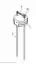
FIG. 1 is an exploded perspective view showing a conventional fuse structure.
FIG. 2 is an assembled view of FIG. 1.
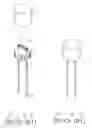
FIG. 3 is a further exploded view of FIG. 1.
FIG. 4 is an assembled view of FIG. 3.
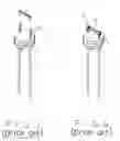
FIG. 5 is an enlarged plan view showing parts of FIG. 1.
FIG. 6 is an enlarged plan view showing parts of FIG. 4.
FIG. 7 is a cross-sectional plan view of FIG. 6.
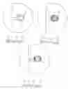
FIG. 8 is an exploded perspective view showing a fuse assembly according to the present invention.
FIG. 9 is an assembled view of FIG. 8.
FIG. 10 is an enlarged plan view showing parts of FIG. 8.
FIG. 11 is an enlarged plan view showing parts of FIG. 9.
FIG. 12 is a cross-sectional plan view of FIG. 11.
DETAILED DESCRIPTION OF THE PREFERRED EMBODIMENT
Referring to FIG. 8 to 12, the present invention relates to an improved fuse assembly, which includes a main body (1), two metal legs (2), and a meltable rod (3), which has its both ends being connected by inner ends (21) of the metal legs (2) respectively. The character of the present invention is in that a thin tin layer (6) is coated evenly between the inner end (21) and the rod (3) without any space.
When the inner end (21) is winded around the rod (3), a thin tin layer (6) has been coated in its inner face in advance. By use of an instance high temperature and pressure from both sides, such as shown in FIG. 11, tin layer (6) will be melted first and fulfilled between the inner end (21) and the rod (3). After cooling, the inner end (21) and the rod (3) can be connected together tightly and tin layer (6) is fulfilled therebetween without any space. It is to be understood that the fuse assembly obtains a perfect electrical connection. It cab be used on any electrical product with a high effective and stable function.
The above-mentioned structure is only an embodiment to illustrate my design and is not to limit the scope of this application. Any modified embodiment with similar merits will be still claimed by the present invention.
Claims
I claim:1. A fuse assembly including a main body, two metal legs, a meltable rod, which has its both ends being connected by inner ends of the metal legs respectively, and a cover, and the character is in that a thin tin layer is connected tightly between the inner end of the metal leg and the rod without any space.
Images & Drawings included:

Sources:
- United States Patent and Trademark Office - verify current appl. status at the USPTO↗
Similar patent applications:
- » 20160079687
Fusible switch assemblies, and load base assemblies, line base assemblies, line bus connector assemblies, fuse clip assemblies, fuse clip and lug assemblies, and operational methods thereof - » 20090322463
Dropout fuse assembly and fuse holder - » 20100127817
Fuse assembly and fuse therefor - » 20100033293
Fuse assembly with a capability of indicating a fusing state by light - » 20090153286
Insulator for cutout switch and fuse assembly - » 20090184797
Fuse assembly with integrated current sensing - » 20090066469
Battery fuse assembly - » 20060214259
Hybrid chip fuse assembly having wire leads and fabrication method therefor - » 20080199559
Mechanical fuse assembly of molding system - » 20060093412
Fusing assembly having a temperature equalizing device
Recent applications in this class:
- » 20240112875 2024-04-04
Lightweight industrial fuse - » 20190371558 2019-12-05
Tuning fork terminal slow blow fuse - » 20180342365 2018-11-29
Tuning fork terminal slow blow fuse - » 20120299692 2012-11-29
Fuse providing overcurrent and thermal protection - » 20120044037 2012-02-23
Blade fuse - » 20110163839 2011-07-07
Fuse structure with power disconnection light indicating function - » 20110163838 2011-07-07
Combination-type fuse - » 20100328018 2010-12-30
Fusible link unit - » 20100219930 2010-09-02
Tuning fork terminal slow blow fuse - » 20100060406 2010-03-11
SMALL-SIZED SURFACE-MOUNTED FUSE AND METHOD OF MANUFACTURING THE SAME