Guidepost for a Road
US20080145145A1
2008-06-19
11/816,818
2006-06-20
Abstract:
A guidepost of a road is disclosed, in which there are provided a groove pipe frame having an insertion groove along an entire length of a circular pipe and a guidepost having an insertion frame inserted into the insertion groove and provided at a backside of a guidepost having various road and traffic information, and the insertion groove of the groove pipe frame and the insertion frame of the guidepost are assembled based on an insertion method, and a rim reinforcing angle is provided for reinforcing the guidepost made of an aluminum plate at an outer side of a backside of the guidepost, and a T-shaped space portion is formed at the insertion frame, with an upper side of the same being opened, and the insertion frame and the guidepost are assembled based on a sliding and insertion method for thereby achieving a simple and easily assembling work in a state that it is loosely installed at the insertion groove of the groove pipe frame using a fixing bolt.
Interested in similar patents?
Get notified when new applications in this technology area are published.
Classification:
G09F7/18 » CPC main
Signs, name or number plates, letters, numerals, or symbols ; Panels or boards Means for attaching signs, plates, panels, or boards to a supporting structure
E01F9/61 » CPC further
Arrangement of road signs or traffic signals; Arrangements for enforcing caution; Upright bodies, e.g. marker posts or bollards; Supports for road signs specially adapted for particular signalling purposes, e.g. for indicating curves, road works or pedestrian crossings for guiding, warning or controlling traffic, e.g. delineator posts or milestones Special features of delineator posts, e.g. with parts cantilevered toward the roadway or fixed vertically on a tilted surface
Description
TECHNICAL FIELD
The present invention relates to a guidepost of a road, and in particular to a guidepost of a road in which there are provided a groove pipe frame having an insertion groove along an entire length of a circular pipe and a guidepost having an insertion frame inserted into the insertion groove and provided at a backside of a guidepost having various road and traffic information, and the insertion groove of the groove pipe frame and the insertion frame of the guidepost are assembled based on an insertion method, and a rim reinforcing angle is provided for reinforcing the guidepost made of an aluminum plate at an outer side of a backside of the guidepost, and a T-shaped space portion is formed at the insertion frame, with an upper side of the same being opened, and the insertion frame and the guidepost are assembled based on a sliding and insertion method for thereby achieving a simple and easily assembling work in a state that it is loosely installed at the insertion groove of the groove pipe frame using a fixing bolt.
BACKGROUND ART
The same application as the present invention has a patent on a guidepost of a road (Korean patent registration No. 483464. According to the patent '464, along an entire length of an upper and lower horizontal frame designed to install a guidepost, an insertion grove of which an opening is narrow, and inner side is wide is formed, and an insertion rim is formed in the same shape as the insertion groove on the upper and lower sides of the guidepost, with the insertion rim being inserted into the insertion groove based on a slide method. With this construction, an installation work of a guidepost of a road is simple and easy, and the guidepost is not broken by a storm.
The same applicant as the present invention has multiple patents and utility models and designs on various road facilities such as a falling rock prevention wall, a road guardrail, a road light shield plate, etc. As a person who manufactures and installs the above road facilities, the applicant discloses a support member which may be commonly used for a pile and a support frame which is vertically or horizontally installed in various road facilities.
The above support member is provided with a rectangular groove formed along an entire length of a circular pipe made of a metal and is commonly adapted to various road facilities for thereby reducing the manufacture cost of the same.
However, in the above technologies, the insertion groove formed along an entire length of the upper and lower horizontal frames, expressed as a support member, is narrow and wider in their inner sides, so that the horizontal frame is used only for the guidepost of a road. So, the manufacture cost of the guidepost of a road increases, and it is not competitive with respect to other companies.
DISCLOSURE OF INVENTION
Accordingly, it is an object of the present invention to provide a guidepost for a road which overcomes the problems encountered in a conventional art.
It is another object of the present invention to provide a guidepost of a road in which when various road facilities such as a road guidepost, a falling rock prevention wall, a road guardrail, and a road light shield plate are manufactured, a groove pipe frame having a rectangular insertion groove is provided along an entire length of a circular pipe made of a metal which may be commonly used for a pile or a support frame, and a guidepost having an insertion frame inserted into the insertion groove is formed at a backside of the guidepost, and an insertion groove of the groove pipe frame and an insertion frame of the guidepost are assembled based on a simple insertion method. With this construction, it is possible to decrease a manufacture cost.
It is further another object of the present invention to provide a guidepost of a road in which a rim reinforcing angle reinforcing a guidepost made of an aluminum plate is installed at an outer side of a backside of the guidepost, and a T-shaped space part is formed at the insertion frame, with an upper surface of the T-shaped space part being cut away, and it is possible to simply assemble in such a manner that the insertion frame and the guidepost are slid in a state that a fixing bolt is loosely inserted into the insertion groove of the groove pipe frame.
To achieve the above objects, in a road guidepost in which a groove pipe frame is horizontally installed at a regular interval at an upper side of a vertical pile which is vertically installed on the ground of a road, and an insertion groove is formed along the groove pipe frame in a longitudinal direction, and an insertion portion of the guidepost is installed based on an insertion method, and a stop rib is installed at an inner portion of the insertion groove inserted with the groove pipe frame for thereby limiting an insertion depth of the guidepost, there is provided a road guidepost characterized in that a rim reinforcing angle is installed at an outer rim of the guidepost for reinforcing the guidepost, and an insertion frame inserted into the insertion groove of the groove pipe frame is horizontally installed at a backside of the guidepost in which the rim reinforcing angle is installed, with the insertion frame having the same length as the is guidepost and being formed over the entire length portions of the back surface of the guidepost, and the insertion frame includes a cut-away portion cut in a longitudinal direction at the center upper portion so that a T shaped space is formed at the upper side of the base portion, and the insertion portions having an engaging shoulder portion at both sides are opposite to each other, and an insertion groove of the groove pipe frame is inserted into an outer side of the insertion portion, and a fixing bolt of which head caught by the engaging shoulder portion of the insertion portion passes through an outer side of the insertion groove and the groove pipe frame and is engaged with a nut by using an interposed washer.
BRIEF DESCRIPTION OF THE DRAWINGS
The present invention will become better understood with reference to the accompanying drawings which are given only by way of illustration and thus are not limitative of the present invention, wherein;
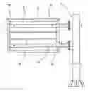
FIG. 1 is a backside view illustrating an installation state of a guidepost of a road according to an embodiment of the present invention;
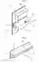
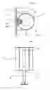
FIG. 2 is an enlarged partial perspective view of the portion A of FIG. 1;
FIG. 3 is a perspective view illustrating an insertion frame which is an important element of an embodiment of FIG. 1 according to the present invention;
FIG. 4 is a partial enlarged cross sectional view illustrating an engaged state of a guidepost and a groove pipe frame of FIG. 1 according to an embodiment of the present invention;
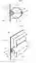
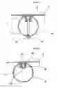
FIG. 5 is a partial perspective view illustrating an engaging state of a guidepost and a groove pipe frame according to a second embodiment of a guidepost of a road of the present invention;
FIG. 6 is a partial cross sectional view illustrating an important portion of FIG. 5;
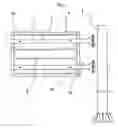
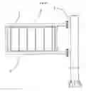
FIGS. 7A and 7B are backside views illustrating an installation state of a guidepost of a road according to a third embodiment of the present invention;
FIG. 8 is a partial enlarged cross sectional view illustrating an engaged state between a guidepost and a groove pipe according to a third embodiment of the present invention in addition to a third embodiment of FIG. 7;
FIG. 9 is a partial enlarged cross sectional view illustrating an engaged structure of a guidepost and a groove pipe according to a fourth embodiment of the present invention in addition to a third embodiment of FIG. 7;
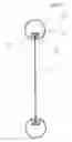
FIG. 10 is a backside view of an installation state of a guidepost of a road according to a fifth embodiment of the present invention; and
FIG. 11 is a lateral cross sectional view of FIG. 10.
BEST MODE FOR CARRYING OUT THE INVENTION
The guidepost of a road according to the present invention will be described with reference to FIGS. 1 through 11.
As shown in FIGS. 1 through 4, the guidepost of a road according to the present invention comprises a vertical pile 1 vertically installed on a road, a groove pipe frame 2 installed at an upper side of the vertical pile 1 in a horizontal direction at a certain interval, and a guidepost 3 which is installed at a front side of the groove pipe frame 2.
In the groove pipe frame 2, a rectangular insertion groove 11 is formed along an entire length, and a stop rib 15 is formed at an inner side of the insertion groove 11 for limiting an insertion depth of the guidepost 3.
In addition, it is obvious that road information or traffic signal is indicated on the front side of the same. A rim reinforcing angle 4 is installed at a rim portion of the backside of the guidepost 3 for reinforcing the guidepost 3 made of an aluminum plate. An insertion frame 5 inserted into the insertion groove 11 of the groove pipe frame 2 is horizontally installed at the backside of the guidepost 3 in which the rim reinforcing angle 4 is installed.
The insertion frame 5 has a cut-away portion 8 formed at the center upper portion in a longitudinal direction so that the T-shaped space portion 7 is formed at the upper side of the base part 6, and the insertion portions 10 having the engaging shoulder portion 9 are opposite to each other. The insertion frame 5 is fixedly engaged along the entire length of the guidepost 3 with the same length as the guidepost 3.
In addition, the insertion groove 11 of the groove pipe frame 2 is inserted into the outer side of the insertion portion 10. The fixing bolt 12 of which head is caught by the engaging shoulder portion 9 of the insertion portion 10 passes through the outer side of the insertion groove 11 and the groove pipe frame 2 and is engaged with the nut 14 by using an interposed washer 13.
As shown in FIGS. 5 and 6 of the second embodiment of the present invention, the construction is same as the first embodiment except for the constructions of the insertion groove 11 of the groove pipe frame 2 and the insertion frame 5a inserted into the insertion groove 11. So, only the different construction will be described.
As shown in FIGS. 5 and 6, in the second embodiment of the present invention, the insertion frame 5a is formed of the insertion portion 16 having a wider upper side and a narrow lower side. The insertion groove 11, into which the insertion portion 16 of which upper side is wide, and lower side is narrow is inserted, is fixedly engaged with the engaging rod 17 to which a narrow neck portion of the insertion portion 16 is engaged at an inner wall of the rectangular entrance. The engaging rod 17 is formed by fixing a circular rod by the length of the guidepost 3.
As shown in FIGS. 7A and 7B and 8 of the third embodiment of the present invention, there are provided a groove pipe 18 which has an insertion groove 11 formed along the entire upper and lower lengths and is vertically installed on the ground, a guidepost 3 installed by inserting the insertion frame 5 into the front surface of the groove pipe 18. Since the construction of the insertion frame 5 and the construction that the insertion frame 5 is engaged at the groove pipe 18 having the insertion groove 1 are the same as the first embodiment of FIGS. 2 and 3, the same construction as the first embodiment will be omitted.
As shown in FIG. 9 according to the fourth embodiment of the present invention, there is provided a guidepost 3 which is vertically installed on the ground at a front side of the cut-away portion 8 forming the insertion groove 11. The engaging structure is same as the second embodiment of FIG. 6, so that the same construction will not be described.
In the third and fourth embodiments of the present invention, the support stopper 19 is installed at both sides of the groove pipe 18 corresponding to the lower end of the guidepost 3 for supporting the lower side of the guidepost 3. FIG. 7A is a view illustrating a construction that one guidepost 3 is installed at one groove pipe 18, and FIG. 7B is a view illustrating a construction that one guidepost 3 is installed at two groove pipes 18.
As shown in FIGS. 10 and 11 according to the fifth embodiment of the present invention, the upper and lower side groove pipe frames 2 are installed at regular intervals at the upper and lower sides of the vertical pile 1 vertically installed on the ground of the road. The insertion grooves 11 formed at the upper and lower side groove pipe frames 2 are opposite to each other, and the engaging rod 17 of FIG. 16 is installed at the entrance of the upper and lower side insertion groves 11. An insertion rim 20 is fixedly engaged at the upper and lower sides of the guidepost 3 with the insertion rim being designed with a wider upper side and a narrow lower side. A stop rib 15 is provided at an inner position of the insertion groove 11 of the upper and lower side groove pipe frame 2 for limiting the insertion depth of the guidepost 3.
The assembling and operation of the present invention will be described with reference to FIGS. 1 through 11.
As shown in FIGS. 1 through 4, when the road guidepost according to the present invention is installed, two groove pipe frames 2 are installed at the upper side of the vertical pile 1 installed on the ground of the road at regular intervals. At this time, the fixing bolt 12 is loosely inserted into the insertion groove 11 formed at the groove pipe frame 2 and the through hole 2a passing through the groove pipe frame 2 and is engaged with a nut 14 at the outer side of the groove pipe frame 2 by using an interposed washer 13.
When the fixing bolt 12 is loosely engaged, a certain gap is formed between the surface having the through hole 2a of the insertion groove 11 and the head part of the fixing bolt 12. The engaging shoulder portion 9 of the insertion part 10 formed at both sides of the insertion frame 5 of the backside of the guidepost 3 is slid into the gap.
At this time, as shown in FIGS. 3 and 4, the insertion frame 5 includes a T shaped space 7 including the cut away portion 8 having an opened upper side, so that the fixing bolt 12 is inserted thereinto. When the inner end of the guidepost 3 is caught by the stop rib 15 formed at the inner insertion groove 11 of the groove frame 2 by pushing the guidepost 2 in a sliding method, the insertion of the guidepost 3 stops, and the nut 14 of the loosely engaged fixing bolt 12 is tightened, so that the guidepost 3 is installed at the groove pipe frame 2.
The head of the fixing bolt 12 is formed in a hexagonal shape or a rectangular shape so that it does not rotate in the T shape space portion 7 formed at the insertion frame 5. When the nut 14 is tightened, the fixing bolt 12 does not rotate, so that the fixing bolt 12 and the nut 14 are stably engaged.
As shown in FIGS. 1 through 4, the rim reinforcing angle 4 is fixedly installed at the rear side of the guidepost 3 of the road guidepost according to the present invention, and the guidepost 3 made of an aluminum plate may be reinforced.
In view of the operation of the second embodiments of FIGS. 5 and 6, the insertion frame 5a having the insertion portion 16 with a wider upper side and a narrow lower side is provided at the backside of the guidepost 3. The engaging rod 17 is fixedly formed at the entrance of both sides of the insertion groove 11 so that the insertion portion 16 having a wider upper side and a narrow lower side is slid and inserted into the insertion groove 11 of the groove pipe frame 2, so that the insertion portion 16n having a wider upper side and a narrow lower side is slid and inserted into the insertion groove 11 of the groove pipe frame 2 which is horizontally installed at the vertical pipe 1.
Since the insertion portion 16 is formed at the insertion frame 5a fixedly installed at the backside of the guidepost 3, the guidepost 3 is inserted into the groove pipe frame 2. When the inner end portion of the guidepost 3 is caught by the stop rib 15 formed at the inner side of the groove pipe frame 2, the insertion stops, and the inner wall surface of the insertion groove 11 of the outer side and the upper surface contacting with the insertion portion 16 are engaged using a screw 11a, so that it is possible to easily and simply fix the guidepost 3 to the groove pipe frame 2.
When the engaging rod 17 is fixed at the entrance of both sides of the insertion groove 11, and the insertion portion having a wider upper side and a narrow lower side is inserted into the insertion groove 11, and the insertion portion 16 having a wider upper side and a narrow lower side is caught by the engaging rod 17, so that it does not escape from the insertion groove 11.
In view of the operation according to the third embodiment of FIGS. 7 and 8, the construction that the insertion groove 11 formed at the groove pipe frame 2 of the first embodiment of FIGS. 1 through 4 is engaged with the insertion frame 5 installed at the backside of the guidepost 3 is same as the third embodiment, the descriptions of the assembling and operation of the third embodiment of the present invention will be omitted.
A different construction between the first embodiment and the third embodiment of the present invention lies in that two groove pipe frames 2 are horizontally installed at the vertical pile 1, and the guidepost 3 is installed at the front surface of two groove pipe frames 2 in the first embodiment, and the groove pipe 18 having the same construction as the groove pipe frame 2 is vertically installed, and the guidepost 3, in which the insertion frame 5 is vertically installed at the front side of the groove pipe 18, is vertically installed.
As shown in FIG. 9 of the fourth embodiment, the construction that the guidepost 3 is vertically installed at the groove pipe 18 is the same as the third embodiment. In addition, the constructions that the insertion portion 16 having a wider upper side and a narrow lower side is slid and inserted into the insertion groove 11 having the entrance rod 17 at the entrance of both sides of the insertion groove 11, and it is engaged with a screw 11 are same, so that the same construction is not described.
As shown in FIGS. 10 and 11 according to the fifth embodiment of the present invention, the upper and lower side groove pipe frames 2 are horizontally installed at the vertical pile 1 which is vertically installed on the ground of the road, and the insertion grooves 11 formed at the upper and lower side groove pipe frames 2 are formed opposite to each other, and as shown in FIG. 6, the engaging rod 17 is formed at the entrance of the upper and lower insertion grooves 11. The insertion rim 20 having a wider upper side and a narrow lower side is fixedly engaged at the upper and lower sides of the guidepost 3, and a stop rib 15 is formed at an inner side of the insertion groove 11 of the upper and lower side groove pipe frame 2 for limiting the insertion depth of the sign post 3. As shown in FIGS. 5 and 6, the insertion portion 16 having a wider upper side and a narrow lower side is slid and inserted into the insertion groove 11 having the engaging rod 17 at the entrance of both sides of the insertion groove 11 and is engaged with a screw. In addition, the insertion rim 20 is slid and engaged with the insertion groove 11 having the engaging rod 17 at the entrance of both sides. The descriptions of the same constructions will be omitted.
INDUSTRIAL APPLICABILITY
In the road guidepost according to the present invention, when various road facilities such as a road guidepost, a falling rock prevention wall, a road guardrail, a road light shield plate, etc is manufactured, a groove pipe frame having a rectangular insertion groove is formed over the entire length of the circular pipe made of a metal and commonly used for the purpose of a column or a support frame. A guidepost includes an insertion frame inserted into the insertion groove at the backside of the guidepost. The insertion groove of the groove pipe frame and the insertion frame of the guidepost are simply assembled based on the insertion method. The manufacturing cost of the guidepost decreases.
In addition, a rim reinforcing angle is installed at a rim of the backside of the guidepost made of an aluminum plate, so that it is possible to reinforce the weak guidepost which is made of an aluminum plate.
As the present invention may be embodied in several forms without departing from the spirit or essential characteristics thereof, it should also be understood that the above-described examples are not limited by any of the details of the foregoing description, unless otherwise specified, but rather should be construed broadly within its spirit and scope as defined in the appended claims, and therefore all changes and modifications that fall within the meets and bounds of the claims, or equivalences of such meets and bounds are therefore intended to be embraced by the appended claims.
Claims
1. In a road guidepost in which a groove pipe frame 2 is horizontally installed at a regular interval at an upper side of a vertical pile 1 which is vertically installed on the ground of a road, and an insertion groove 11 is formed along the groove pipe frame 2 in a longitudinal direction, and an insertion portion of the guidepost 3 is installed based on an insertion method, and a stop rib 15 is installed at an inner portion of the insertion groove 11 inserted with the groove pipe frame 2 for thereby limiting an insertion depth of the guidepost 3, a road guidepost characterized in that a rim reinforcing angle 4 is installed at an outer rim of the guidepost 3 for reinforcing the guidepost 3, and an insertion frame 5 inserted into the insertion groove 11 of the groove pipe frame 2 is horizontally installed at a backside of the guidepost 3 in which the rim reinforcing angle 4 is installed, with the insertion frame 5 having the same length as the guidepost and being formed over the entire length portions of the back surface of the guidepost 3, and the insertion frame 5 includes a cut-away portion 8 cut in a longitudinal direction at the center upper portion so that a T shaped space 7 is formed at the upper side of the base portion 6, and the insertion portions 10 having an engaging shoulder portion 9 at both sides are opposite to each other, and an insertion groove 11 of the groove pipe frame 2 is inserted into an outer side of the insertion portion 10, and a fixing bolt 12 of which head is caught by the engaging shoulder portion 9 of the insertion portion 10 passes through an outer side of the insertion groove 11 and the groove pipe frame 2 and is engaged with a nut 14 by using an interposed washer.
2. In a road guidepost in which a groove pipe frame 2 is horizontally installed at a regular interval at an upper side of a vertical pile 1 which is vertically installed on the ground of a road, and an insertion groove 11 is formed along the groove pipe frame 2 in a longitudinal direction, and an insertion portion of the guidepost 3 is installed based on an insertion method, and a stop rib 15 is installed at an inner portion of the insertion groove 11 inserted with the groove pipe frame 2 for thereby limiting an insertion depth of the guidepost 3, a road guidepost characterized in that a rim reinforcing angle 4 is installed at an outer rim of the guidepost 3 for reinforcing the guidepost 3, and an insertion frame 5 inserted into the insertion groove 11 of the groove pipe frame 2 is horizontally installed at a backside of the guidepost 3 in which the rim reinforcing angle 4 is installed, with the insertion frame 5a having the same length as the guidepost and being formed over the entire length portions of the back surface of the guidepost 3, and the insertion frame 5a is provided with the insertion portion 16 inserted into the insertion groove 11 being provided at an upper side of the base portion 6 and being formed with a wider upper side and a narrow lower side, and an engaging rod 17 caught by a neck portion of the insertion portion 16 is fixedly engaged at an inner wall of both sides of the entrance of the insertion groove 11 into which the insertion portion 16 is inserted, and a support stopper 19 is installed at both sides of the groove pipe 18 corresponding to the lower end of the guidepost 3 for supporting the lower side of the guidepost 3, and the inner wall of the insertion groove 11 and the upper surface contacting with the insertion portion 16 are engaged using a screw 11a.
3. In a road guidepost in which a guidepost 3 is installed at a vertical pile vertically installed on the ground of a road, a road guidepost characterized in that said vertical pile includes a groove pipe 18 having an insertion groove 11 along the entire upper and lower lengths of one side of a circular pipe, and an insertion frame 5 inserted into the insertion groove 11 of the groove pipe 18 is formed at the backside of the guidepost 3 along the entire length of the backside of the guidepost 3 with the same length as the guidepost 3 in the vertical direction, and the insertion frame 5 includes a cut-away portion 8 cut in a longitudinal direction at the center upper portion so that a T shaped space 7 is formed at the upper side of the base portion 6, and the insertion portions 10 having an engaging shoulder portion 9 at both sides are opposite to each other, and an insertion groove 11 of the groove pipe frame 2 is inserted into an outer side of the insertion portion 10, and a fixing bolt 12 of which head is caught by the engaging shoulder portion 9 of the insertion portion 10 passes through an outer side of the insertion groove 11 and the groove pipe frame 2 and is engaged with a nut 14 by using an interposed washer.
4. In a road guidepost in which a guidepost 3 is installed at a vertical pile vertically installed on the ground of a road, a road guidepost characterized in that said vertical pile includes a groove pipe 18 having an insertion groove 11 along the entire upper and lower lengths of one side of a circular pipe, and an insertion frame 5a inserted into the insertion groove 11 of the groove pipe 18 is formed at the backside of the guidepost 3 along the entire length of the backside of the guidepost 3 with the same length as the guidepost 3 in the vertical direction, and the insertion frame 5a is provided with the insertion portion 16 inserted into the insertion groove 11 being provided at an upper side of the base portion 6 and being formed with a wider upper side and a narrow lower side, and an engaging rod 17 caught by a neck portion of the insertion portion 16 is fixedly engaged at an inner wall of both sides of the entrance of the insertion groove 11 into which the insertion portion 16 is inserted, and a support stopper 19 is installed at both sides of the groove pipe 18 corresponding to the lower end of the guidepost 3 for supporting the lower side of the guidepost 3, and the inner wall of the insertion groove 11 and the upper surface contacting with the insertion portion 16 are engaged using a screw 11a.
Images & Drawings included:
Sources:
- United States Patent and Trademark Office - verify current appl. status at the USPTO↗
Recent applications in this class:
- » 20250157363 2025-05-15
Temporary Road Sign Device - » 20250140135 2025-05-01
Sign Board Leg Accommodating Ground Stake and Method of Use - » 20250124826 2025-04-17
SIGN ASSEMBLY - » 20250124825 2025-04-17
Improved Adjustable Canvas Wrap Frame Mounting System - » 20250087118 2025-03-13
PLACARD MOUNTING STRUCTURE - » 20250078689 2025-03-06
SOFT SIGNAGE DISPLAY - » 20250037616 2025-01-30
ADVERTISING SYSTEM - » 20250014484 2025-01-09
NONDESTRUCTIVE WINDOW MOUNTABLE SILICONE EDGE GRAPHIC - » 20240420602 2024-12-19
SIGN HOLDER APPARATUS - » 20240363035 2024-10-31
License Plate Holder