Axial flow fan
US20080145230A1
2008-06-19
11/906,060
2007-09-28
✅ Patent granted
US 8,328,522 B2
2012-12-11
-
-
Dwayne J White
2031-05-23
Abstract:
A fan or rotor design where the surface profile may be configured to desired dimensions particular to a given operating environment is disclosed.
Inventors:
- Paul LEES 6 🇺🇸 San Francisco, CA, United States
- Jayden David Harman 25 🇺🇸 San Rafael, CA, United States
- Kimberly Penney 2 🇺🇸 Emeryville, CA, United States
- Onno Koelman 1 🇺🇸 San Anselmo, CA, United States
Assignee:
- Pax Scientific, Inc. 1 🇺🇸 Grass Valley, CA, United States
Interested in similar patents?
Get notified when new applications in this technology area are published.
Classification:
F04D29/384 » CPC main
Details, component parts, or accessories; Rotors specially for elastic fluids for axial flow pumps; Blades characterised by form
G06F30/20 » CPC further
Computer-aided design [CAD] Design optimisation, verification or simulation
G06F2111/10 » CPC further
Details relating to CAD techniques Numerical modelling
Y10T29/49321 » CPC further
Metal working; Method of mechanical manufacture; Impeller making; Turbomachine making Assembling individual fluid flow interacting members, e.g., blades, vanes, buckets, on rotary support member
Y10T29/49327 » CPC further
Metal working; Method of mechanical manufacture; Impeller making Axial blower or fan
F04D29/38 IPC
Details, component parts, or accessories; Rotors specially for elastic fluids for axial flow pumps Blades
F01D5/14 IPC
Blades; Blade-carrying members ; Heating, heat-insulating, cooling or antivibration means on the blades or the members; Blades Form or construction
B23P15/04 IPC
Making specific metal objects by operations not covered by a single other subclass or a group in this subclass turbine or like blades from several pieces
F03B3/12 IPC
Machines or engines of reaction type; Parts or details peculiar thereto Blades; Blade-carrying rotors
Description
CROSS-REFERENCE TO RELATED APPLICATIONS
The present application claims the priority benefit of U.S. provisional patent application No. 60/827,677 filed Sep. 29, 2006 and entitled “Axial Flow Fan” and U.S. provisional patent application No. 60/950,610 filed Jul. 19, 2007 and entitled “Surface Profile for a Quiet Rotor or Stator.” The disclosure of these commonly owned applications are incorporated herein by reference.
This application is related to U.S. Pat. No. 5,934,877 for a “Rotor with Logarithmic Scaled Shape” and U.S. Pat. No. 6,702,552 for an “Impeller Having Blade(s) Conforming to the Golden Section of a Logarithmic Curve.” The disclosures of these commonly owned patents are incorporated herein by reference.
BACKGROUND OF THE INVENTION
1. Field of the Invention
The present invention generally concerns axial flow fans and rotors. More specifically, the present invention concerns a surface profile for axial flow fans and rotors used in environments requiring high output in conjunction with constrained fan size including but not limited to electronics cooling.
2. Description of the Related Art
Fan and rotor design has undergone little change over the past century. As a result, fans and rotors remain relatively inefficient. A part of this inefficiency is the result of fans and rotors generating a considerable amount of noise and turbulence. Similarly, fans and rotors used in liquid environments typically result in cavitation. Noise, turbulence, and cavitation reduce the operational efficiency of the fan and rotor.
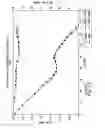
A chart illustrating inefficiencies with respect to flow and sound in a series of 92×38 mm computer fans as found in the prior art are shown in FIG. 1A. A similar chart illustrating inefficiencies with respect to flow and torque in prior art fan design is shown in FIG. 1B. FIG. 1B illustrates, specifically, a 22″ best-in-class A/C fan with a standard bell shroud operating at 850 rpm.
Much of the noise, turbulence, and unwanted torque in prior art fan design may be attributable to the surface design of the fan or rotor. In many instances, fans and rotors are implemented in a particular operating environment based on a pre-existing design. These pre-existing designs are not necessarily designed or intended for that particular operating environment. Nevertheless, these pre-existing designs may achieve results that are adequate or ‘good enough’ for that particular environment.
Determining which pre-existing design is adequate or ‘good enough’ for a particular environment is a never-ending exercise. Trial and error will continually redefine the best adequate or ‘good enough’ design implementation. Notwithstanding these adequate results, some degree of the aforementioned noise, turbulence, and/or unwanted torque will inevitably remain.
There is, therefore, a need in the art for fan and rotor design where the surface profile may be configured to desired dimensions particular to a given operating environment.
SUMMARY OF THE INVENTION
Embodiments of the present invention provide for an axial flow fan that is quieter for the same or better output throughout a range of operating points compared to prior art fan designs. References to an axial flow fan or any fan are meant to be inclusive with respect to rotors and other blade designs.
In one exemplary embodiment, a method for constructing an axial fan is disclosed. In this exemplary method, a spline is drafted to connect a plurality of points along a radius cut sketch to form a blade surface. The blade surface is then offset by a constant amount and filled to form a single blade. The single blade is oriented with respect to a hub and patterned along with a total number of blades to be affixed to the hub. The single blade and remaining blades are then attached to the hub.
In another embodiment, a fan apparatus is disclosed. The fan apparatus includes a hub a blade coupled to the hub, the blade including a blade surface. The blade surface is created by drafting a spline to connect a plurality of points along a radius cut sketch. The blade is created by offsetting the blade surface by a constant amount and filling the blade surface to form a single blade.
Another exemplary method provides for constructing an axial fan. The exemplary method includes drafting a spline to connect a plurality of points along a radius cut sketch to form a blade surface. A complimentary airfoil shape is then created. The airfoil is then lofted into a solid.
A computer-readable storage medium is also disclosed. The medium has embodied thereon a program being executable by a processor to perform a method for constructing an axial fan.
BRIEF DESCRIPTION OF THE DRAWINGS
FIG. 1A is a chart exhibiting flow and sound inefficiencies in prior art fan design.
FIG. 1B is a chart exhibiting flow and torque inefficiencies in prior art fan design.
FIG. 2A is a chart exhibiting flow and sound efficiency of a fan as may be designed in accordance with an exemplary embodiment of the present invention as compared to the inefficiencies of prior art fans like those shown in FIG. 1A.
FIG. 2B is a chart exhibiting flow and torque efficiency of a fan as may be designed in accordance with an exemplary embodiment of the present invention as compared to the inefficiencies of a prior art fan like that shown in FIG. 1B.
FIG. 3 illustrates an exemplary fan and surface profile according to an embodiment of the present invention.
FIG. 4 illustrates an exemplary surface profile of a fan blade according to an alternative embodiment of the present invention.
FIG. 5 illustrates an exemplary method for constructing a blade surface according to an embodiment of the present invention.
FIG. 6 illustrates a method for forming a blade according to an embodiment of the present invention.
FIG. 7 illustrates an alternative method for forming a blade according to an embodiment of the present invention.
FIG. 8 illustrates an exemplary method for constructing a fan according to an embodiment of the present invention.
FIGS. 9A-9E illustrate exemplary fans constructed utilizing the surface profile disclosed with respect to FIG. 3.
FIGS. 10A-10E illustrate exemplary fans constructed utilizing the surface profile disclosed with respect to FIG. 4.
DETAILED DESCRIPTION
Embodiments of the present invention provide for a fan that is quieter for the same or better output throughout a range of operating points compared to prior art fan designs. FIG. 2A is a chart exhibiting flow and sound efficiency of an exemplary fan as may be designed in accordance with the present invention compared to the inefficiencies of a prior art fan like that found in FIG. 1A. FIG. 2B, in turn, is a chart exhibiting flow and torque efficiency of an exemplary surface profile as may be designed for a fan in accordance with the present invention compared to the inefficiencies of a prior art fan like that found in FIG. 1B.
FIG. 3 illustrates a portion of an exemplary fan 300 and surface profile 330 according to an embodiment of the present invention. Fan 300 may be motor driven or subject to the natural flow of a fluid (e.g., liquid or gas). Fan 300 includes a hub 310, which may be approximately cylindrical or conical in shape. Hub 310 may be hollowed like that of FIG. 9A or solid as is shown in FIG. 10E. Hub 310 may also include a cap like that shown in FIG. 9B. Hub 310 may be altered with radii, chamfers, and/or blends with symmetry about the Y-axis as illustrated throughout FIGS. 9 and 10. Hub 310 may be configured to an appropriate height and diameter in order to incorporate a desired motor and hub-tip ratio as illustrated throughout FIGS. 9 and 10.
Blades 320 are circularly patterned around hub 310. Blades 320 may be permanently or temporarily coupled or affixed to the hub 310 through various techniques as known in the art. The surface profile 330 of blades 320 may be configured in accordance with the various profiles described in U.S. Pat. Nos. 5,934,877 and 6,702,552, the disclosure of which has been previously incorporated herein by reference. For example, a portion of the surface profile 330 of fan blade 320 may conform to a logarithmic spiral. The radius of that particular logarithmic spiral may unfold at a constant order of growth when measured at equiangular radii, which may sometimes be referred to as the Golden Section.
Surface profile 330 configurations may also correspond to external or internal shell configurations as found in nature. For example, the surface profile 330 of blade 320 may conform to the shell of the phylum Mollusca, class Cephalopoda, genus Nautilus. An alternative surface profile-to-shell configuration may be inclusive of the shell shaping of the phylum Mollusca, class Gastropoda, genus Conus, Conidae, Turbinidea, or Volutidae. Shell configurations from other members of phylum Mollusca, class Gastropoda or Cephalopoda may also be implemented with respect to the surface profile 330 of blade 320.
Various other surface configurations may be implemented in accordance with embodiments of the present invention. For example, surface profile 330 of blade 320 may be defined by the following tables. In Tables I-IX, Cartesian points are taken at even intervals along the span of the blade, which corresponds to an 87 mm diameter fan. In the context of FIG. 3, axis Y represents the hub axis and serves as the zero reference for all radial measurements. All dimensions in Tables I-IX are in millimeters. The blade surface may be constructed through a method like that disclosed in the context of FIG. 5.
| TABLE I |
| 22.5 mm Radius |
| Pt # | X | Y | Z | |
| 1 | −5.389 | −2.463 | 21.845 | |
| 2 | −2.804 | −0.447 | 22.325 | |
| 3 | −1.548 | 0.621 | 22.447 | |
| 4 | −0.338 | 1.725 | 22.497 | |
| 5 | 4.187 | 6.381 | 22.107 | |
| 6 | 6.236 | 8.883 | 21.619 | |
| 7 | 8.171 | 11.467 | 20.964 | |
| 8 | 9.981 | 14.098 | 20.165 | |
| 9 | 11.645 | 16.791 | 19.252 | |
| 10 | 12.675 | 18.611 | 18.590 | |
| TABLE II |
| 25 mm Radius |
| Pt# | X | Y | Z | |
| 1 | −6.755 | −3.085 | 24.070 | |
| 2 | −5.230 | −1.984 | 24.447 | |
| 3 | −3.708 | −0.850 | 24.723 | |
| 4 | −2.209 | 0.344 | 24.902 | |
| 5 | −0.743 | 1.590 | 24.989 | |
| 6 | 0.680 | 2.866 | 24.991 | |
| 7 | 2.072 | 4.159 | 24.914 | |
| 8 | 4.740 | 6.826 | 24.547 | |
| 9 | 7.203 | 9.653 | 23.940 | |
| 10 | 9.536 | 12.571 | 23.110 | |
| 11 | 11.695 | 15.578 | 22.096 | |
| 12 | 13.656 | 18.668 | 20.941 | |
| TABLE III |
| 27.5 mm Radius |
| Pt # | X | Y | Z | |
| 1 | −8.339 | −3.663 | 26.205 | |
| 2 | −6.681 | −2.508 | 26.676 | |
| 3 | −5.014 | −1.334 | 27.039 | |
| 4 | −3.379 | −0.118 | 27.292 | |
| 5 | −1.774 | 1.140 | 27.443 | |
| 6 | −0.200 | 2.438 | 27.499 | |
| 7 | 1.360 | 3.757 | 27.466 | |
| 8 | 2.898 | 5.107 | 27.347 | |
| 9 | 4.395 | 6.508 | 27.147 | |
| 10 | 5.841 | 7.963 | 26.873 | |
| 11 | 7.233 | 9.452 | 26.532 | |
| 12 | 9.896 | 12.488 | 25.658 | |
| 13 | 12.351 | 15.634 | 24.571 | |
| 14 | 14.594 | 18.869 | 23.308 | |
| TABLE IV |
| 30 mm Radius |
| Pt # | X | Y | Z | |
| 1 | −10.052 | −4.175 | 28.266 | |
| 2 | −8.259 | −2.972 | 28.841 | |
| 3 | −6.454 | −1.744 | 29.298 | |
| 4 | −2.895 | 0.799 | 29.860 | |
| 5 | −1.145 | 2.119 | 29.978 | |
| 6 | 0.589 | 3.464 | 29.994 | |
| 7 | 2.300 | 4.847 | 29.912 | |
| 8 | 3.968 | 6.289 | 29.736 | |
| 9 | 5.597 | 7.786 | 29.473 | |
| 10 | 7.177 | 9.315 | 29.129 | |
| 11 | 10.171 | 12.444 | 28.223 | |
| 12 | 11.578 | 14.055 | 27.676 | |
| 13 | 12.919 | 15.705 | 27.076 | |
| 14 | 15.426 | 19.108 | 25.730 | |
| TABLE V |
| 32.5 mm Radius |
| Pt # | X | Y | Z | |
| 1 | −11.904 | −4.628 | 30.241 | |
| 2 | −8.077 | −2.121 | 31.480 | |
| 3 | −6.134 | −0.832 | 31.916 | |
| 4 | −4.200 | 0.476 | 32.227 | |
| 5 | −0.387 | 3.180 | 32.498 | |
| 6 | 3.326 | 6.035 | 32.329 | |
| 7 | 5.121 | 7.551 | 32.094 | |
| 8 | 6.879 | 9.111 | 31.764 | |
| 9 | 10.229 | 12.302 | 30.848 | |
| 10 | 13.307 | 15.645 | 29.651 | |
| 11 | 16.096 | 19.177 | 28.234 | |
| TABLE VI |
| 35 mm Radius |
| Pt # | X | Y | Z | |
| 1 | −13.944 | −5.042 | 32.102 | |
| 2 | −11.950 | −3.756 | 32.897 | |
| 3 | −9.913 | −2.465 | 33.567 | |
| 4 | −7.835 | −1.168 | 34.112 | |
| 5 | −5.747 | 0.160 | 34.525 | |
| 6 | −1.625 | 2.908 | 34.962 | |
| 7 | 2.419 | 5.778 | 34.916 | |
| 8 | 4.393 | 7.286 | 34.723 | |
| 9 | 6.319 | 8.865 | 34.425 | |
| 10 | 10.022 | 12.110 | 33.535 | |
| 11 | 11.778 | 13.779 | 32.959 | |
| 12 | 13.453 | 15.502 | 32.311 | |
| 13 | 15.045 | 17.284 | 31.602 | |
| 14 | 16.552 | 19.129 | 30.839 | |
| TABLE VII |
| 37.5 mm Radius |
| Pt # | X | Y | Z | |
| 1 | −16.217 | −5.442 | 33.812 | |
| 2 | −14.137 | −4.107 | 34.733 | |
| 3 | −12.003 | −2.783 | 35.527 | |
| 4 | −9.813 | −1.473 | 36.193 | |
| 5 | −7.592 | −0.132 | 36.724 | |
| 6 | −3.163 | 2.655 | 37.366 | |
| 7 | 1.205 | 5.545 | 37.481 | |
| 8 | 3.361 | 7.039 | 37.349 | |
| 9 | 5.468 | 8.607 | 37.099 | |
| 10 | 7.519 | 10.247 | 36.738 | |
| 11 | 9.510 | 11.916 | 36.274 | |
| 12 | 11.447 | 13.606 | 35.710 | |
| 13 | 13.311 | 15.339 | 35.058 | |
| 14 | 15.077 | 17.149 | 34.335 | |
| 15 | 16.736 | 19.050 | 33.558 | |
| TABLE VIII |
| 40 mm Radius |
| Pt # | X | Y | Z | |
| 1 | −18.694 | −5.801 | 35.363 | |
| 2 | −16.540 | −4.436 | 36.420 | |
| 3 | −14.332 | −3.083 | 37.344 | |
| 4 | −12.065 | −1.755 | 38.137 | |
| 5 | −9.759 | −0.412 | 38.791 | |
| 6 | −7.428 | 0.970 | 39.304 | |
| 7 | −5.073 | 2.390 | 39.677 | |
| 8 | −0.382 | 5.301 | 39.998 | |
| 9 | 4.225 | 8.324 | 39.776 | |
| 10 | 6.454 | 9.943 | 39.476 | |
| 11 | 8.614 | 11.644 | 39.062 | |
| 12 | 10.707 | 13.380 | 38.540 | |
| 13 | 12.752 | 15.132 | 37.913 | |
| 14 | 14.711 | 16.945 | 37.197 | |
| 15 | 16.538 | 18.880 | 36.421 | |
| TABLE IX |
| 42.5 mm Radius |
| Pt # | X | Y | Z | |
| 1 | −21.317 | −6.090 | 36.767 | |
| 2 | −19.109 | −4.701 | 37.962 | |
| 3 | −16.842 | −3.324 | 39.020 | |
| 4 | −12.129 | −0.612 | 40.732 | |
| 5 | −9.709 | 0.774 | 41.376 | |
| 6 | −7.262 | 2.199 | 41.875 | |
| 7 | −2.365 | 5.103 | 42.434 | |
| 8 | 0.080 | 6.575 | 42.500 | |
| 9 | 2.514 | 8.074 | 42.426 | |
| 10 | 4.912 | 9.640 | 42.215 | |
| 11 | 7.231 | 11.300 | 41.880 | |
| 12 | 9.460 | 13.033 | 41.434 | |
| 13 | 11.633 | 14.797 | 40.877 | |
| 14 | 13.759 | 16.584 | 40.211 | |
| 15 | 15.754 | 18.503 | 39.472 | |
FIG. 4 illustrates an exemplary surface profile 410 of a fan blade 400 according to an alternative embodiment of the present invention. Surface profile 410 may correspond to a blade coupled or affixed to a hub like the fan 300 shown in FIG. 3. The surface profile 410 of fan blade 400 in FIG. 4 has been defined by the Cartesian points as referenced in Tables X-XXVI (below) and taken at even intervals along the axis of the fan blade 400. The X, Y, and Z axis are orthogonal to one another and oriented as shown in FIG. 4. Like tables I-IX, all dimensions are in millimeters.
| TABLE X |
| z = 0 mm |
| X | Y | |
| −15.143 | −23.188 | |
| −14.326 | −22.832 | |
| −13.543 | −22.424 | |
| −12.092 | −21.431 | |
| −10.769 | −20.241 | |
| −9.567 | −18.931 | |
| −8.467 | −17.536 | |
| −7.442 | −16.078 | |
| −5.577 | −13.054 | |
| −3.900 | −9.921 | |
| −2.423 | −6.683 | |
| −1.140 | −3.369 | |
| 0.000 | 0.000 | |
| 1.470 | 5.110 | |
| 2.078 | 7.697 | |
| 2.576 | 10.311 | |
| 3.158 | 15.563 | |
| 3.063 | 20.820 | |
| 2.698 | 23.451 | |
| 2.425 | 24.763 | |
| 2.094 | 26.055 | |
| 0.214 | 31.012 | |
| −0.392 | 32.199 | |
| −1.055 | 33.364 | |
| −2.543 | 35.567 | |
| −4.264 | 37.579 | |
| −6.176 | 39.433 | |
| TABLE XI |
| z = 5 mm |
| X | Y | |
| −11.448 | −21.282 | |
| −10.262 | −20.347 | |
| −9.220 | −19.270 | |
| −8.278 | −18.093 | |
| −7.405 | −16.861 | |
| −5.804 | −14.307 | |
| −4.345 | −11.667 | |
| −3.026 | −8.955 | |
| −1.861 | −6.181 | |
| −0.828 | −3.356 | |
| 0.111 | −0.493 | |
| 1.605 | 4.777 | |
| 2.219 | 7.445 | |
| 2.718 | 10.142 | |
| 3.285 | 15.559 | |
| 3.152 | 20.975 | |
| 2.756 | 23.684 | |
| 2.464 | 25.033 | |
| 2.110 | 26.361 | |
| 0.100 | 31.441 | |
| −0.550 | 32.655 | |
| −1.259 | 33.838 | |
| −2.848 | 36.059 | |
| −4.681 | 38.070 | |
| −6.717 | 39.906 | |
| TABLE XII |
| z = 10 mm |
| X | Y | |
| −9.055 | −19.049 | |
| −8.218 | −18.097 | |
| −7.448 | −17.100 | |
| −6.051 | −15.004 | |
| −4.790 | −12.815 | |
| −3.650 | −10.566 | |
| −1.700 | −5.933 | |
| −0.091 | −1.161 | |
| 1.427 | 4.243 | |
| 2.559 | 9.716 | |
| 3.150 | 15.287 | |
| 3.183 | 18.115 | |
| 3.003 | 20.923 | |
| 1.906 | 26.433 | |
| 1.465 | 27.782 | |
| 0.961 | 29.098 | |
| −0.226 | 31.637 | |
| −1.658 | 34.046 | |
| −2.476 | 35.197 | |
| −3.368 | 36.305 | |
| −5.342 | 38.334 | |
| −7.510 | 40.159 | |
| TABLE XIII |
| z = 15 mm |
| X | Y | |
| −7.636 | −16.833 | |
| −6.407 | −15.142 | |
| −5.294 | −13.382 | |
| −3.400 | −9.666 | |
| −1.841 | −5.788 | |
| −0.520 | −1.823 | |
| 1.028 | 3.721 | |
| 2.187 | 9.359 | |
| 2.794 | 15.067 | |
| 2.623 | 20.801 | |
| 2.171 | 23.646 | |
| 1.454 | 26.416 | |
| 0.460 | 29.106 | |
| −0.142 | 30.420 | |
| −0.810 | 31.697 | |
| −4.123 | 36.335 | |
| −5.129 | 37.364 | |
| −6.209 | 38.335 | |
| −8.496 | 40.128 | |
| TABLE XIV |
| z = 20 mm |
| X | Y | |
| −6.748 | −14.747 | |
| −5.797 | −13.336 | |
| −4.930 | −11.879 | |
| −3.443 | −8.825 | |
| −1.117 | −2.431 | |
| 0.442 | 3.175 | |
| 1.607 | 8.854 | |
| 2.225 | 14.633 | |
| 2.247 | 17.565 | |
| 2.033 | 20.472 | |
| 1.556 | 23.345 | |
| 1.212 | 24.767 | |
| 0.793 | 26.176 | |
| −1.576 | 31.479 | |
| −3.193 | 33.910 | |
| −4.118 | 35.055 | |
| −5.109 | 36.129 | |
| −7.282 | 38.061 | |
| −9.650 | 39.775 | |
| TABLE XV |
| z = 25 mm |
| X | Y | |
| −6.097 | −12.664 | |
| −5.414 | −11.525 | |
| −4.785 | −10.362 | |
| −3.674 | −7.973 | |
| −1.861 | −3.015 | |
| −0.288 | 2.627 | |
| 0.863 | 8.346 | |
| 1.461 | 14.168 | |
| 1.463 | 17.118 | |
| 1.220 | 20.041 | |
| 0.706 | 22.931 | |
| −0.102 | 25.770 | |
| −1.196 | 28.484 | |
| −2.586 | 31.057 | |
| −3.400 | 32.287 | |
| −4.294 | 33.466 | |
| −6.282 | 35.609 | |
| −8.535 | 37.464 | |
| −10.991 | 39.098 | |
| TABLE XVI |
| z = 30 mm |
| X | Y | |
| −5.585 | −10.399 | |
| −4.067 | −7.100 | |
| −2.804 | −3.695 | |
| −1.189 | 1.944 | |
| −0.064 | 7.667 | |
| 0.486 | 13.491 | |
| 0.463 | 16.449 | |
| 0.189 | 19.383 | |
| −0.363 | 22.272 | |
| −0.751 | 23.699 | |
| −1.217 | 25.108 | |
| −3.828 | 30.353 | |
| −4.679 | 31.560 | |
| −5.615 | 32.715 | |
| −7.690 | 34.793 | |
| −10.027 | 36.564 | |
| −12.561 | 38.097 | |
| TABLE XVII |
| z = 35 mm |
| X | Y | |
| −5.162 | −7.551 | |
| −4.098 | −4.761 | |
| −2.368 | 0.873 | |
| −1.217 | 6.608 | |
| −0.708 | 12.454 | |
| −0.704 | 13.936 | |
| −0.758 | 15.427 | |
| −1.060 | 18.379 | |
| −1.647 | 21.280 | |
| −2.058 | 22.709 | |
| −2.552 | 24.119 | |
| −3.772 | 26.814 | |
| −5.307 | 29.331 | |
| −6.199 | 30.519 | |
| −7.177 | 31.651 | |
| −9.340 | 33.665 | |
| −11.769 | 35.341 | |
| −14.399 | 36.754 | |
| TABLE XVIII |
| z = 40 mm |
| X | Y | |
| −4.536 | −2.789 | |
| −3.114 | 2.520 | |
| −2.292 | 7.928 | |
| −2.135 | 10.675 | |
| −2.170 | 13.441 | |
| −2.907 | 18.884 | |
| −3.250 | 20.222 | |
| −3.664 | 21.546 | |
| −4.704 | 24.098 | |
| −6.028 | 26.505 | |
| −6.800 | 27.653 | |
| −7.645 | 28.755 | |
| −9.517 | 30.760 | |
| −11.648 | 32.479 | |
| −14.038 | 33.894 | |
| −16.570 | 35.051 | |
| TABLE XIX |
| z = 45 mm |
| X | Y | |
| −3.952 | 5.610 | |
| −3.744 | 9.858 | |
| −4.047 | 14.086 | |
| −4.411 | 16.191 | |
| −4.929 | 18.258 | |
| −6.455 | 22.212 | |
| −6.949 | 23.159 | |
| −7.488 | 24.086 | |
| −8.690 | 25.845 | |
| −10.056 | 27.471 | |
| −11.599 | 28.952 | |
| −13.298 | 30.240 | |
| −15.124 | 31.311 | |
| −17.062 | 32.195 | |
| −19.063 | 32.962 | |
| TABLE XX |
| z = −5 mm |
| X | Y | |
| −19.764 | −24.408 | |
| −18.389 | −24.124 | |
| −17.077 | −23.624 | |
| −14.607 | −22.303 | |
| −12.354 | −20.650 | |
| −11.318 | −19.698 | |
| −10.354 | −18.686 | |
| −7.038 | −14.217 | |
| −5.603 | −11.812 | |
| −4.294 | −9.345 | |
| −2.231 | −4.690 | |
| −0.511 | 0.098 | |
| 0.964 | 5.079 | |
| 2.097 | 10.148 | |
| 2.738 | 15.274 | |
| 2.712 | 20.412 | |
| 2.387 | 22.987 | |
| 2.136 | 24.271 | |
| 1.829 | 25.537 | |
| 0.074 | 30.408 | |
| −0.494 | 31.579 | |
| −1.117 | 32.730 | |
| −2.524 | 34.917 | |
| −4.159 | 36.924 | |
| −5.979 | 38.785 | |
| TABLE XXI |
| z = −10 mm |
| X | Y | |
| −21.148 | −24.550 | |
| −19.540 | −23.946 | |
| −17.984 | −23.240 | |
| −15.006 | −21.576 | |
| −13.608 | −20.570 | |
| −12.302 | −19.447 | |
| −9.977 | −16.914 | |
| −8.556 | −14.998 | |
| −7.262 | −13.011 | |
| −4.973 | −8.872 | |
| −3.030 | −4.542 | |
| −1.367 | −0.074 | |
| 0.131 | 4.783 | |
| 1.301 | 9.730 | |
| 2.016 | 14.737 | |
| 2.087 | 19.764 | |
| 1.814 | 22.288 | |
| 1.591 | 23.550 | |
| 1.314 | 24.796 | |
| −0.307 | 29.601 | |
| −1.426 | 31.897 | |
| −2.762 | 34.067 | |
| −4.328 | 36.060 | |
| −6.086 | 37.906 | |
| TABLE XXII |
| z = −15 mm |
| X | Y | |
| −21.794 | −24.790 | |
| −20.175 | −23.944 | |
| −18.591 | −23.032 | |
| −17.082 | −22.071 | |
| −15.621 | −21.055 | |
| −12.915 | −18.773 | |
| −10.552 | −16.093 | |
| −8.510 | −13.142 | |
| −5.128 | −6.869 | |
| −3.707 | −3.589 | |
| −2.436 | −0.232 | |
| −0.930 | 4.469 | |
| 0.255 | 9.261 | |
| 1.019 | 14.115 | |
| 1.181 | 18.994 | |
| 0.970 | 21.446 | |
| 0.540 | 23.894 | |
| −0.937 | 28.601 | |
| −1.982 | 30.851 | |
| −3.246 | 32.984 | |
| −4.740 | 34.943 | |
| −6.430 | 36.756 | |
| TABLE XXIII |
| z = −20 mm |
| X | Y | |
| −22.214 | −26.282 | |
| −20.683 | −24.942 | |
| −19.172 | −23.578 | |
| −17.670 | −22.205 | |
| −16.180 | −20.819 | |
| −14.728 | −19.392 | |
| −13.353 | −17.905 | |
| −10.889 | −14.728 | |
| −8.742 | −11.328 | |
| −6.831 | −7.765 | |
| −3.661 | −0.323 | |
| −2.183 | 4.174 | |
| −1.014 | 8.742 | |
| −0.234 | 13.401 | |
| −0.037 | 15.773 | |
| −0.005 | 18.144 | |
| −0.510 | 22.827 | |
| −1.071 | 25.139 | |
| −1.836 | 27.393 | |
| −3.977 | 31.617 | |
| −4.658 | 32.603 | |
| −5.400 | 33.542 | |
| −7.006 | 35.315 | |
| TABLE XXIV |
| z = −25 mm |
| X | Y | |
| −22.961 | −27.642 | |
| −22.018 | −26.664 | |
| −21.095 | −25.669 | |
| −19.289 | −23.642 | |
| −15.812 | −19.472 | |
| −12.680 | −15.049 | |
| −9.911 | −10.389 | |
| −8.345 | −7.520 | |
| −6.615 | −4.030 | |
| −5.102 | −0.441 | |
| −3.634 | 3.837 | |
| −3.014 | 6.011 | |
| −2.481 | 8.210 | |
| −1.722 | 12.644 | |
| −1.476 | 17.128 | |
| −1.592 | 19.393 | |
| −1.890 | 21.635 | |
| −3.064 | 25.986 | |
| −3.957 | 28.073 | |
| −5.049 | 30.035 | |
| −6.358 | 31.855 | |
| −7.844 | 33.558 | |
| TABLE XXV |
| z = −30 mm |
| X | Y | |
| −4.440 | 6.519 | |
| −3.341 | 13.018 | |
| −3.243 | 16.316 | |
| −3.330 | 17.977 | |
| −3.515 | 19.623 | |
| −4.193 | 22.849 | |
| −4.700 | 24.428 | |
| −5.326 | 25.969 | |
| −6.933 | 28.834 | |
| −8.986 | 31.417 | |
| TABLE XXVI |
| z = −35 mm |
| X | Y | |
| −5.258 | 14.085 | |
| −5.583 | 18.053 | |
| −5.972 | 20.003 | |
| −6.524 | 21.926 | |
| −8.139 | 25.532 | |
| −9.219 | 27.183 | |
| −10.437 | 28.755 | |
Both prototype and manufactured surfaces resulting from the application of Tables I-IX and Tables X-XXVI may conform to these points within reasonable process tolerances.
FIG. 5 illustrates an exemplary method 500 for constructing a blade surface according to an embodiment of the present invention. In step 510, a radius cut is sketched. Points are identified along that radius cut in step 520 and a spline is drafted to connect the aforementioned points in step 530. In step 540, each radius cut sketch is lofted in increasing radius order to form a surface. The surface may be extended or trimmed at the edges to reach the exact desired dimensions in step 550.
FIG. 6 illustrates a method 600 for forming a blade according to an embodiment of the present invention. In step 610, the surface (as may be created through the method described with respect to FIG. 5) is offset by a constant amount. In step 620, the offset is filled to form a single blade. In optional step 630, the bluntness of the leading and/or trailing edges may be altered for desired operating conditions.
FIG. 7 illustrates an alternative method 700 for forming a blade according to an embodiment of the present invention. In step 710, a complimentary airfoil shape is created. In step 720, a semi- or fully-airfoil blade cross-section is created on one or both sides of the blade. This cross-section may then be lofted into a solid in step 730. Alterations may also be made with respect to the bluntness of the leading and/or trailing edges for the purpose of desired operating conditions in step 740.
FIG. 8 illustrates an exemplary method 800 for constructing a fan according to an embodiment of the present invention. In step 810, blades are oriented with respect to the hub, which may include rotating the in-tact blade surface about an axis to change the pitch, dihedral, or sweep angle as they pertain to desired fan performance. The blade is then patterned around the hub or other fixturing device in step 820 for the appropriate number of blades. Blades can be fully or partially attached to the hub in step 830 and radiused as desired. Alterations may also be made to the leading and/or trailing edge bluntness in order to achieve desired operation conditions.
While Tables I-IX, for example, dictate an 87 mm diameter fan, the blade surface, full blade, and/or final fan may be scaled to change the size and output of the fan as may the measurements set forth in Tables X-XXVI. The resulting fan blade may be mirrored or run in either rotation. Additional attributes may be added to the fan including radii, mid-blade or blade-tip winglets (vertical extrusions out of the blade), full or partial-depth rings, extended or indented turbulators (bumps or cavities along the blade to change boundary layer behavior or noise), embossings, fastening devices, coatings and so forth. Additional surface features and/or strategic roughness may be employed. Furthermore, this blade surface may also be used in a similar fashion to make a non-rotating fan, or stator.
The methods disclosed with respect to FIGS. 5-8 may be embodied in computer software. A computer-readable storage medium may have embodied thereon a program. The program may be executable by a processor to perform the methods or combinations thereof as disclosed herein. These methods may be applicable in the field of computer-aided drafting or design, which may include three-dimensional design tools. The results of such computer-aided drafting and design may be rendered on a display device (e.g., a computer monitor) or printed to a tangible medium such as a computer printout. These results may be annotated with measurement information.
FIGS. 9A-9E illustrate exemplary fans constructed utilizing the surface profile disclosed with respect to FIG. 3. These fan configurations are exemplary and various elements thereof (e.g., hub, blade number, blade configuration, stators) may be interchangeably combined with one another and in conjunction with a particular surface profile to construct a fan in accordance with an embodiment of the present invention.
FIG. 9A illustrates an exemplary fan including five blades arranged about a cylindrical and hollowed hub.
FIG. 9B illustrates another exemplary fan including seven blades arranged about a cylindrical and capped hub.
FIG. 9C illustrates an exemplary fan including five blades with serrated edges and arranged about a conical hub.
FIG. 9D illustrates an exemplary fan including twelve blades with a notched edge and arranged about a cylindrical and capped hub.
FIG. 9E illustrates an exemplary fan including two blades and arranged about a cylindrical hub, the fan being enclosed within a stator.
FIGS. 10A-10E illustrate exemplary fans constructed utilizing the surface profile disclosed with respect to FIG. 4. These fan configurations are exemplary and various elements thereof (e.g., hub, blade number, blade configuration, stators) may be interchangeably combined with one another and in conjunction with a particular surface profile to construct a fan in accordance with an embodiment of the present invention.
FIG. 10A illustrates an exemplary fan including three blades extending outward in three-dimensions from an otherwise flat, two-dimensional hub.
FIG. 10B illustrates an exemplary fan including six blades and arranged about a cylindrical and solid hub, the fan being enclosed within a stator.
FIG. 10C illustrates an exemplary fan including three blades extending outward in three-dimensions from a conical hub.
FIG. 10D illustrates an exemplary fan including fourteen blades and arranged about a cylindrical hub, each of the blades being coupled to one another by intermediate ‘webbing.’
FIG. 10E illustrates an exemplary fan including four blades and arranged about a cylindrical and solid hub.
While the present invention has been described with reference to exemplary embodiments, it will be understood by those skilled in the art that various changes may be made and equivalents may be substituted for elements or steps thereof without departing from the true spirit and scope of the present invention. For example, methods of design may be applied to methods of manufacture.
Claims
What is claimed is:1. A method for axial fan design, the method comprising:
drafting a spline to connect a plurality of points along a radius cut sketch to form a blade surface;
offsetting the blade surface by a constant amount;
filling the blade surface to form a single blade;
orienting the single blade with respect to a hub;
patterning the single blade with a total number of blades to be affixed to the hub around the hub; and
attaching the single blade and the remaining blades from the total number of blades to the hub.
2. The method of claim 1, wherein the plurality of points are connected in increasing radius order.
3. The method of claim 1, further comprising extending the blade surface at an edge to achieve a desired dimension.
4. The method of claim 1, further comprising trimming the blade surface at an edge to achieve a desired dimension.
5. The method of claim 1, wherein orienting the single blade includes rotating the blade surface about an axis to change a pitch angle.
6. The method of claim 1, wherein orienting the single blade includes rotating the blade surface about an axis to change a dihedral angle.
7. The method of claim 1, wherein orienting the single blade includes rotating the blade surface about an axis to change a sweep angle.
8. The method of claim 1, wherein the attachment is temporary.
9. The method of claim 1, wherein the attachment is permanent.
10. The method of claim 1, wherein a portion of the blade surface conforms to a logarithmic spiral, the radius of the logarithmic spiral unfolding at a constant order of growth when measured at equiangular radii.
11. The method of claim 1, wherein a portion of the blade surface conforms to an internal or external shell configuration from the phylum Mollusca and classes Gastropoda or Cephalopoda.
12. A fan apparatus, comprising:
a hub; and
a blade coupled to the hub, the blade including a blade surface, wherein the blade surface is designed by drafting a spline to connect a plurality of points along a radius cut sketch and the blade is designed by offsetting the blade surface by a constant amount and filling the blade surface to form a single blade.
13. The fan apparatus of claim 12, wherein the plurality of points are connected in increasing radius order.
14. The fan apparatus of claim 12, wherein the blade surface has been extended at an edge to achieve a desired dimension.
15. The fan apparatus of claim 12, wherein the blade surface has been rotated about an axis with respect to the orientation of the blade surface to the hub.
16. The fan apparatus of claim 15, wherein the rotation about the axis changes a pitch angle, dihedral angle, or sweep angle.
17. A method for axial fan design, the method comprising:
drafting a spline to connect a plurality of points along a radius cut sketch to form a blade surface;
creating a complimentary airfoil shape;
lofting the airfoil shape into a solid;
orienting the solidified blade with respect to a hub;
patterning the solidified blade with a total number of blades to be affixed to the hub around the hub; and
attaching the solidified blade and the remaining blades from the total number of blades to the hub.
18. The method of 17, further comprising altering a leading edge or trailing edge bluntness of the blade surface.
19. The method of claim 17, wherein the airfoil shape is created on a first side of the blade surface.
20. The method of claim 17, wherein the airfoil shape is created on the second side of the blade surface.
21. The method of claim 17, wherein the airfoil blade is partially based on the surface.
22. The method of claim 17, wherein the airfoil blade is fully based on the surface.
23. A computer-readable storage medium having embodied thereon a program, the program being executable by a processor to perform a method for axial fan design, the method comprising:
drafting a spline to connect a plurality of points along a radius cut sketch to form a blade surface;
offsetting the blade surface by a constant amount;
filling the blade surface to form a single blade;
orienting the single blade with respect to a hub;
patterning the single blade with a total number of blades to be affixed to the hub around the hub; and
displaying the single blade and the remaining blades from the total number of blades as being attached to the hub.
24. A computer-readable storage medium having embodied thereon a program, the program being executable by a processor to perform a method for axial fan design, the method comprising:
drafting a spline to connect a plurality of points along a radius cut sketch to form a blade surface;
creating a complimentary airfoil shape;
lofting the airfoil shape into a solid blade;
orienting the solidified blade with respect to a hub;
patterning the solidified blade with a total number of blades to be affixed to the hub around the hub; and
displaying the solidified blade and the remaining blades from the total number of blades as being attached to the hub.
Images & Drawings included:


Sources:
- United States Patent and Trademark Office - verify current appl. status at the USPTO↗
Similar patent applications:
- » 20180058479
IMPELLER FOR AN AXIAL FLOW FAN AND AXIAL FLOW FAN - » 20130156561
Impeller for axial flow fan and axial flow fan using the same - » 20110240268
Super low noise fan blades, axial flow fans incorporating the same, and commercial air cooled apparatuses incorporating such axial flow fans - » 20150167678
AXIAL FLOW FAN AND SERIES AXIAL FLOW FAN - » 20130170995
AXIAL FLOW FAN BLADE STRUCTURE AND AXIAL FLOW FAN THEREOF - » 20180142702
Inlet nozzle for a radial, diagonal or axial-flow fan, and a radial, diagonal or axial-flow fan comprising an inlet nozzle - » 20180003190
Axial flow fan and air-conditioning apparatus having axial flow fan - » 20130045085
Motor suspension for fans, preferably axial-flow fans, as well as method for manufacturing an air grille of such a motor suspension - » 20180142708
Fan frame of an axial-flow fan - » 10744376
Axial-flow fan structure
Recent applications in this class:
- » 20250283481 2025-09-11
AEROELASTIC FAN BLADE - » 20250264113 2025-08-21
THERMAL STRATIFICATION MIXER FOR AN AIR HANDLING UNIT - » 20250250987 2025-08-07
IMPELLER FOR A DUCT - » 20250243873 2025-07-31
FAN BLADE, FAN AND FAN LAMP - » 20250198423 2025-06-19
IMPELLER, FAN, AND AIR-CONDITIONING APPARATUS - » 20250198422 2025-06-19
AXIAL FAN ASSEMBLY INCLUDING AN INTERMEDIATE SHROUD - » 20250198421 2025-06-19
FAN BLADE STRUCTURE - » 20250188947 2025-06-12
Stepped Leading Edge Fan Blade - » 20250172158 2025-05-29
BLADE FOR AN INDUSTRIAL AXIAL FAN WITH TIP LIFT APPENDAGE - » 20250067277 2025-02-27
INDUSTRIAL AXIAL FAN BLADE