Imaging lens and imaging device including the imaging lens
US20080151394A1
2008-06-26
11/986,152
2007-11-20
✅ Patent granted
US 7,450,323 B2
2008-11-11
-
-
Timothy J Thompson
2027-11-20
Abstract:
It is to provide an imaging lens and an imaging device including the imaging lens that can secure telecentricity and achieve excellent resolution through sufficient correction of various aberrations, while being compact and light.
The imaging lens comprises, in order from an object side to an image surface side, a first lens 2 that is a meniscus lens having a positive power whose convex surface faces the object side, a diaphragm 3, a second lens 4 that is a meniscus lens having a negative power whose convex surface faces the image surface side, and a third lens 5 that is a meniscus lens having a negative power whose convex surface faces the object side, wherein conditions expressed by −130≦f2/fl≦−6 and 0.8≦f1/fl≦1 (where, fl: focal distance of the entire lens system, f1: focal distance of the first lens, and f2: focal distance of the second lens) are to be satisfied.
Assignee:
- Enplas Corporation 533 🇯🇵 Saitama, Japan
Interested in similar patents?
Get notified when new applications in this technology area are published.
Classification:
G02B13/0035 » CPC main
Optical objectives specially designed for the purposes specified below; Miniaturised objectives for electronic devices, e.g. portable telephones, webcams, PDAs, small digital cameras characterised by the lens design having at least one aspherical surface having three lenses
G02B13/18 » CPC further
Optical objectives specially designed for the purposes specified below with lenses having one or more non-spherical faces, e.g. for reducing geometrical aberration
G02B13/22 » CPC further
Optical objectives specially designed for the purposes specified below Telecentric objectives or lens systems
G02B9/12 » CPC further
Optical objectives characterised both by the number of the components and their arrangements according to their sign, i.e. + or - having three components only
Description
BACKGROUND OF THE INVENTION
1. Field of the Invention
The present invention relates to an imaging lens and an imaging device including the imaging lens. In particular, the present invention relates to an imaging lens and an imaging device including the imaging lens, in which the imaging lens has a three-lens structure that is capable of size and weight reduction. The imaging lens is used in an image-taking device that uses an image sensor element, such as a charge-coupled device (CCD) and a complementary metal oxide semiconductor (CMOS), mounted on a portable computer, a television phone, a portable phone, and the like.
2. Description of the Related Art
In recent years, there has been an increasing demand for cameras that utilize an image sensor element, such as the CCD, the CMOS, or the like, that is mounted on a portable computer, a television phone, a portable phone, a digital camera, and the like. It is demanded that a camera such as this is small and light because the camera is required to be mounted on a limited installation space.
Therefore, it is also necessary for the imaging lens used in such cameras to be similarly small and light. Conventionally, a single-lens structure lens system using a single lens and a two-lens structure lens system having two lenses have been used as such an imaging lens.
However, although such lens systems with a small number of lenses are extremely effective in reducing the size and weight of the lens system, the lens systems cannot sufficiently handle high image quality and high resolution required of the imaging lenses in recent years.
Therefore, conventionally, a three-lens structure lens system using three lenses is used to handle high image quality and high resolution. The three lenses are a first lens, a second lens set on an object surface side of the first lens, and a third lens set on the object surface side of the second lens.
As examples of such a three-lens structure lens system attempting to increase resolution, for example, the lens systems described in the following Patent Literatures 1 to 3 are known.
[Patent Literature 1] Japanese Patent Unexamined Publication 2001-75006
[Patent Literature 2] Japanese Patent Unexamined Publication 2003-149545
[Patent Literature 3] Japanese Patent Unexamined Publication Heisei 10-301021
However, in the lens system described in Patent Literature 1, a diaphragm is disposed closest to the object side. Therefore, correction of distortion and chromatic aberration caused by magnification is difficult. A first lens is a meniscus lens whose convex surface faces an image surface side. Therefore, the lens system is not suitable for size and weight reduction. A second lens is shaped having a concave surface on the image surface side. Therefore, total reflection easily occurs and correction of off-axis aberration is difficult.
In the lens system described in Patent Literature 2, a first lens has negative power. Therefore, size and weight reduction is difficult.
Furthermore, in the lens system described in Patent Literature 3, a diaphragm is disposed between a second lens and a third lens. The third lens has a strong concave surface facing an object side and negative power. Therefore, telecentricity is poor. Moreover, an effective diameter of the third lens is large because space between the second lens and the third lens is wide. Therefore, the lens system is not suitable for size and weight reduction.
Therefore, the conventional lens systems were insufficient for securing telecentricity and achieving excellent resolution through sufficient correction of various aberrations, while achieving size and weight reduction.
SUMMARY OF THE INVENTION
The present invention has been achieved in light of the above-described problems. An object of the invention is to provide an imaging lens and an imaging device including the imaging lens, in which the imaging lens can secure telecentricity and achieve excellent resolution through sufficient correction of various aberrations, while being compact and light.
In order to achieve the aforementioned object, an imaging lens according to a first aspect of the present invention is an imaging lens used for forming an image of an object on an image-taking surface of an image sensor element comprising, in order from an object side to an image surface side: a first lens that is a meniscus lens having a positive power whose convex surface faces the object side, a diaphragm, a second lens that is a meniscus lens having a negative power whose convex surface faces the image surface side, and a third lens that is a meniscus lens having a negative power whose convex surface faces the object side, wherein conditions expressed by the following expressions (1) and (2) are to be satisfied:
−130≦f2/fl≦−6 (1)
0.8≦f1/fl≦1 (2)
where,
fl: focal distance of the entire lens system
f1: focal distance of the first lens
f2: focal distance of the second lens.
In the first aspect of the invention, the first lens is a meniscus lens having a positive power whose convex surface faces the object side. The second lens is a meniscus lens having a negative power whose convex surface faces the image surface side. The third lens is a meniscus lens having a negative power whose convex surface faces the object side. The diaphragm is disposed between the first lens and the second lens. In addition, the conditions expressed by the expressions (1) and (2) are satisfied. Therefore, the size of the optical system can be reduced, telecentricity can be secured, and various aberrations, such as coma aberration, chromatic aberration, and field curvature can be successfully corrected.
An imaging lens according to a second aspect is the imaging lens according to the first aspect, wherein, further, a condition expressed by a following expression (3) is to be satisfied:
10≦(r5+r6)/(r5−r6)≦25 (3)
where,
r5: center radius curvature of the object side face of the third lens
r6: center radius curvature of the image surface side face of the third lens.
In the second aspect of the present invention, further, the expression (3) is satisfied. Therefore, telecentricity can be further enhanced and field curvature can be more successfully corrected.
An imaging lens according to a third aspect is the imaging lens according to the first aspect, wherein, further, a condition expressed by a following expression (4) is to be satisfied:
0.5≦r5/fl≦1.1 (4).
In the third aspect of the invention, further, the expression (4) is satisfied. Therefore, coma aberration and distortion can be more successfully corrected.
An imaging lens according to a fourth aspect is the imaging lens according to the first aspect, wherein, further, a condition expressed by a following expression (5) is to be satisfied:
0<r1/r2≦0.5 (5)
where,
r1: center radius curvature of the object side face of the first lens
r2: center radius curvature of the image surface side face of the first lens.
In the fourth aspect of the present invention, further, the expression (5) is satisfied. Therefore, spherical aberration can be successfully corrected while reducing the size of the optical system.
An imaging device according to a fifth aspect includes the imaging lens according to any one of aspects 1 to 4 and an image sensor element.
In the fifth aspect of the present invention, further, a compact and light imaging device having high image quality can be achieved by an imaging lens that can reduce the size and weight of the optical system, secure telecentricity, and successfully correct various aberrations, such as coma aberration, chromatic aberration, and field curvature, being included.
EFFECT OF THE INVENTION
In the imaging lens and the imaging device including the imaging lens of the invention, telecentricity can be secured and excellent resolution can be achieved through sufficient correction of various aberrations, while being compact and light.
In particular, a high-performance imaging lens that is compact and has a short optical length can be actualized.
BRIEF DESCRIPTION OF THE DRAWINGS
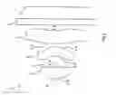
FIG. 1 is a schematic diagram for showing an embodiment of an imaging lens and an imaging device including the imaging lens according to the present invention;
FIG. 2 is a schematic diagram for showing a FIRST EXAMPLE of the imaging lens according to the present invention;
FIG. 3 shows graphs for describing the spherical aberration, astigmatism, and distortion of the imaging lens shown in FIG. 2;
FIG. 4 is a schematic diagram for showing a SECOND EXAMPLE of the imaging lens according to the present invention;
FIG. 5 shows graphs for describing the spherical aberration, astigmatism, and distortion of the imaging lens shown in FIG. 4;
FIG. 6 is a schematic diagram for showing a THIRD EXAMPLE of the imaging lens according to the present invention;
FIG. 7 shows graphs for describing the spherical aberration, astigmatism, and distortion of the imaging lens shown in FIG. 6;
FIG. 8 is a schematic diagram for showing a FOURTH EXAMPLE of the imaging lens according to the present invention;
FIG. 9 shows graphs for describing the spherical aberration, astigmatism, and distortion of the imaging lens shown in FIG. 8;
FIG. 10 is a schematic diagram for showing a FIFTH EXAMPLE of the imaging lens according to the present invention;
FIG. 11 shows graphs for describing the spherical aberration, astigmatism, and distortion of the imaging lens shown in FIG. 10;
FIG. 12 is a schematic diagram for showing a SIXTH EXAMPLE of the imaging lent according to the present invention;
FIG. 13 shows graphs for describing the spherical aberration, astigmatism, and distortion of the imaging lens shown in FIG. 12;
FIG. 14 is a schematic diagram for showing a SEVENTH EXAMPLE of the imaging lens according to the present invention;
FIG. 15 shows graphs for describing the spherical aberration, astigmatism, and distortion of the imaging lens shown in FIG. 14;
FIG. 16 is a schematic diagram for showing an EIGHTH EXAMPLE of the imaging lens according to the present invention;
FIG. 17 shows graphs for describing the spherical aberration, astigmatism, and distortion of the imaging lens shown in FIG. 16;
FIG. 18 is a schematic diagram for showing a NINTH EXAMPLE of the imaging lens according to the present invention; and
FIG. 19 shows graphs for describing the spherical aberration, astigmatism, and distortion of the imaging lens shown in FIG. 18.
FIG. 20 is a schematic diagram for showing a TENTH EXAMPLE of the imaging lens according to the present invention;
FIG. 21 shows graphs for describing the spherical aberration, astigmatism, and distortion of the imaging lens shown in FIG. 20.
FIG. 22 is a schematic diagram for showing a ELEVENTH EXAMPLE of the imaging lens according to the present invention;
FIG. 23 shows graphs for describing the spherical aberration, astigmatism, and distortion of the imaging lens shown in FIG. 22.
FIG. 24 is a schematic diagram for showing a TWELFTH EXAMPLE of the imaging lens according to the present invention;
FIG. 25 shows graphs for describing the spherical aberration, astigmatism, and distortion of the imaging lens shown in FIG. 24.
FIG. 26 is a schematic diagram for showing a THIRTEENTH EXAMPLE of the imaging lens according to the present invention;
FIG. 27 shows graphs for describing the spherical aberration, astigmatism, and distortion of the imaging lens shown in FIG. 26.
FIG. 28 is a schematic diagram for showing a FOURTEENTH EXAMPLE of the imaging lens according to the present invention;
FIG. 29 shows graphs for describing the spherical aberration, astigmatism, and distortion of the imaging lens shown in FIG. 28.
FIG. 30 is a schematic diagram for showing a FIFTEENTH EXAMPLE of the imaging lens according to the present invention; and
FIG. 31 shows graphs for describing the spherical aberration, astigmatism, and distortion of the imaging lens shown in FIG. 30.
DETAILED DESCRIPTION OF THE PREFERRED EMBODIMENT
An embodiment of the imaging lens and the imaging device including the imaging lens according to the present invention will be described hereinafter with reference to FIG. 1.
As shown in FIG. 1, an imaging lens 1 according to the embodiment comprises, in order from the object side toward the image surface side, a first lens 2 that is a meniscus lens having a positive power whose convex surface faces the object side, a diaphragm 3, a second lens 4 that is a meniscus lens having a negative power whose convex surface faces the image surface side, and a third lens 5 that is a meniscus lens having a negative power whose convex surface faces the object side. Each lens 2, lens 4, and lens 5 are formed at a low cost using an injection-molding method using resin material.
Hereafter, respective lens surfaces 2a, 4a, and 5a on the object side of the first lens 2, the second lens 4, and the third lens 5 are referred to as first face 2a, first face 4a, and first face 5a of each lens 2, lens 4, and lens 5. Respective lens surfaces 2b, 4b, and 5b on the image surface side of the first lens 2, the second lens 4, and the third lens 5 are referred to as second face 2b, second face 4b, and second face 5b of each lens 2, lens 4, and lens 5.
On the image surface side the third lens 5, there are respectively disposed various filters 6, such as a cover glass, an infrared (IR) cut filter, and a lowpass filter, and an image-taking surface 7 that is a light-receiving surface of an image sensor element (solid image sensor element), such as a CCD or a CMOS. The imaging device is composed of the image sensor element, the lens 2, the lens 4, the lens 5, and the diaphragm 3. The various filters 6 may be omitted as required.
In this way, according to the embodiment, the first lens 2 is a meniscus lens having a positive power whose convex surface faces the object side. Therefore, the optical system can be made compact. In addition, the imaging lens 1 and the imaging device can be made compact and light.
According to the embodiment, the diaphragm 3 is disposed between the first lens 2 and the second lens 4. The diaphragm 3 can be disposed in a position away from the image surface. Therefore, telecentricity can be secured and, compared to when the diaphragm 3 is disposed on the object side of the first lens 2, distortion can be successfully corrected.
According to the embodiment, the second lens 4 is a meniscus lens having a negative power whose convex surface faces the image surface side. Therefore, coma aberration, field curvature and the like can be successfully corrected. When the first face 4a and the second face 4b of the second lens 4 are aspheric surfaces, the effect of aberration correction can be enhanced.
According to the embodiment, the third lens 5 is a meniscus lens having a negative power whose convex surface faces the object side. Therefore, telecentricity can be secured. When the second face 5b of the third lens 5 is an aspheric surface, aberrations at each image height can be effectively corrected. In other words, each light beam incident on the optical system from each object point on an object plane is separated by image height after passing through the diaphragm 3. When the third lens 5 is a lens of which the convex surface faces the object side, each light beam incident on the first face 5a of the third lens 5 after passing through the diaphragm 3 can be more effectively separated by the first face 5a. The aberrations (particularly the astigmatism) of each light beam separated by image height can be effectively corrected by each light beam, by the second face 5b of the third lens 5 that is an aspheric surface.
In addition to such a configuration, according to the embodiment, conditions expressed by the following expressions (1) and (2) are satisfied:
−130≦f2/fl≦−6 (1)
0.8≦f1/fl≦1 (2)
where, fl in the expression (1) is the focal distance of the entire lens system (the same applies hereafter). f2 in the expression (1) is the focal distance of the second lens 4 (the same applies hereafter). f1 in the expression (2) is the focal distance of the first lens 2 (the same applies hereafter).
When the value of f2/fl is greater than the value (−6) in the expression (1), the negative power of the second lens 4 becomes too strong. Coma aberration worsens and Petzval sum becomes excessively corrected. At the same time, when the value of f2/fl is less than the value (−130) in the expression (1), the negative power of the second lens 4 becomes too weak. Telecentricity deteriorates and chromatic aberration is insufficiently corrected.
Therefore, according to the embodiment, by the value of f2/fl being set to satisfy the expression (1), telecentricity can be further enhanced. Various aberrations, such as coma aberration, chromatic aberration, and field curvature, can be more successfully corrected.
The relationship between f2 and fl is more preferably −80≦f2/fl≦−6.
When the value of f1/fl is greater than the value (1) in the expression (2), the power of the first lens 2 becomes too weak. Size reduction of the optical system becomes difficult. At the same time, when the value of f1/fl is less than the value (0.8) in the expression (2), the power of the first lens 2 becomes too strong. Aberration correction becomes difficult.
Therefore, according to the embodiment, by the value of f1/fl being set to satisfy the expression (2), telecentricity can be further enhanced. Both size reduction (in other words, the size and weight reduction of the imaging lens 1 and the imaging device) and enhanced performance of the optical system can be achieved.
The relationship between f1 and fl is more preferably 0.8≦f1/fl≦0.93.
In addition to the above-described configuration, according to the embodiment, a condition expressed by a following expression (3) is satisfied:
10≦(r5+r6)/(r5−r6)≦25 (3)
where, r5 in the expression (3) is the center radius curvature of the first face 5a of the third lens 5 (the same applies hereafter). r6 in the expression (3) is the center radius curvature of the second face 5b of the third lens 5 (the same applies hereafter).
When the value of (r5+r6)/(r5−r6) is greater than the value (25) in the expression (3), although telecentricity is advantageously affected, the correction of field curvature becomes difficult. At the same time, when the value of (r5+r6)/(r5−r6) is less than the value (10) in the expression (3), telecentricity deteriorates and the correction of field curvature becomes difficult.
Therefore, according to the embodiment, by the value of (r5+r6)/(r5−r6) being set to satisfy the expression (3), telecentricity can be further enhanced and field curvature can be more successfully corrected.
The value of (r5+r6)/(r5−r6) is more preferably 12≦(r5+r6)/(r5−r6)≦20.
In addition to the above-described configuration, according to the embodiment, a condition expressed by a following expression (4) is satisfied:
0.5≦r5/fl≦1.1 (4)
When the value of r5/fl is greater than the value (1.1) in the expression (4), the correction of coma aberration becomes difficult. At the same time, when the value of r5/fl is less than the value (0.5) in the expression (4), distortion deteriorates.
Therefore, according to the embodiment, by the value of r5/fl being set to satisfy the expression (4), coma aberration and distortion can be more successfully corrected.
The relationship between r5 and fl is more preferably 0.6≦r5/fl≦0.9.
In addition to the above-described configuration, according to the embodiment, a condition expressed by a following expression (5) is satisfied:
0<r1/r2≦0.5 (5)
where, r1 in the expression (5) is the center radius curvature of the first face 2a of the first lens 2 (the same applies hereafter) r2 in the expression (5) is the center radius curvature of the second face 2b of the first lens (the same applies hereafter).
When the value of r1/r2 is greater than the value (0.5) in the expression (5), the spherical aberration of the second face 2b of the first lens 2 increases and the size reduction of the optical system becomes difficult. At the same time, when the value of r1/r2 is the value (0) in the expression (5) or less, the spherical aberration of the first face 2a of the first lens 2 increases.
Therefore, according to the embodiment, by the value of r1/r2 being set to satisfy the expression (5), spherical aberration can be successfully corrected while reducing the size of the optical system.
The relationship between r1 and r2 is more preferably 0.1≦r1/r2≦0.41.
EXAMPLES
Next, EXAMPLES of the present invention will be described with reference to FIG. 2 to FIG. 31.
In the EXAMPLES, F no denotes F number, ω denotes half of the angle-of-view (angle of view of opposing angles), and r denotes the radius curvature of an optical surface (center radius curvature of a lens surface). Further, d denotes a distance to the next optical surface, nd denotes the index of refraction of each optical system when the d line (yellow) is irradiated, and vd denotes the Abbe number of each optical system also when the d line is irradiated.
k, A, B, C, and D denote each coefficient in a following expression (6). Specifically, the shape of the aspherical surface of the lens is expressed by the following expression provided that the direction of the optical axis 8 is taken as the Z axis, the direction orthogonal to the optical axis 8 (height direction) as the X axis, the traveling direction of light is positive, k is the constant of cone, A, B, C, and D are the aspherical coefficients, and r is the center radius curvature.
Z(X)=r−1X2/[1+{1−(k+1)r−2X2}1/2]+AX4+BX6+CX8+DX10 (6)
In the following EXAMPLES, reference code E used for a numerical value denoting the constant of cone and the aspherical coefficient indicates that the numerical value following E is an exponent having 10 as the base and that the numerical value before E is multiplied by the numerical value denoted by the exponent having 10 as the base. For example, 5.4E-1 denotes 5.4×10⁻¹.
First Example
FIG. 2 shows a FIRST EXAMPLE of the present invention. The imaging lens 1 according to the FIRST EXAMPLE shown in FIG. 2 is the same imaging lens 1 as that shown in FIG. 1. In the example, a cover glass serving as the filter 6 is disposed between the second face 5b of the third lens 5 and the image-taking surface 7.
The imaging lens 1 of the FIRST EXAMPLE was set under the following conditions:
| Lens Data |
| fl = 2.91 mm, f1 = 2.65 mm, f2 = −126.03 mm, F no = 2.8, ω = 63.2° |
| Face Number | r | d | nd | νd |
| (Object Point) | ||||
| 1(First Face of First Lens) | 1.15 | 0.56 | 1.5310 | 56 |
| 2(Second Face of First Lens) | 5.27 | 0.06 | ||
| 3(Diaphragm) | 0.00 | 0.55 | ||
| 4(First Face of Second Lens) | −0.79 | 0.46 | 1.5850 | 30 |
| 5(Second Face of Second Lens) | −0.97 | 0.15 | ||
| 6(First Face of Third Lens) | 2.08 | 0.66 | 1.5310 | 56 |
| 7(Second Face of Third Lens) | 1.84 | 0.30 | ||
| 8(First Face of Cover Glass) | 0.00 | 0.30 | 1.5168 | 64 |
| 9(Second Face of Cover Glass) | 0.00 | |||
| (Image Surface) | ||||
| Face | |||||
| Number | k | A | B | C | D |
| 1 | −7.2 | 5.4E−1 | −7.2E−1 | 9.1E−1 | −5.9E−1 |
| 2 | 0 | −8.9E−3 | −3.7E−2 | −4.0E−1 | 5.8E−1 |
| 4 | −3.0E−1 | 2.0E−1 | −9.0E−1 | 4.0 | −5.7 |
| 5 | −1.0 | −6.8E−2 | 2.4E−1 | 3.2E−1 | −2.8E−1 |
| 6 | −2.6E+1 | −6.9E−2 | 8.2E−2 | −3.6E−2 | 5.1E−3 |
| 7 | −1.4E+1 | −1.0E−1 | 2.7E−2 | −7.9E−4 | −1.6E−3 |
Under such conditions, f2/fl=−43 was achieved, thereby satisfying the expression (1). f1/fl=0.91 was achieved, thereby satisfying the expression (2). (r5+r6)/(r5−r6)=17 was achieved, thereby satisfying the expression (3). r5/fl=0.71 was achieved, thereby satisfying the expression (4). r1/r2=0.22 was achieved, thereby satisfying the expression (5).
FIG. 3 shows the spherical aberration, the astigmatism and the distortion in the imaging lens 1 of the FIRST EXAMPLE.
According to the result, each of the spherical aberration, the astigmatism, and the distortion was almost satisfied. It can be seen from the result that a sufficiently excellent optical property can be obtained.
Second Example
FIG. 4 shows a SECOND EXAMPLE of the present invention. In the example, as in the FIRST EXAMPLE, a cover glass serving as the filter 6 is disposed between the second face 5b of the third lens 5 and the image-taking surface 7.
The imaging lens 1 of the SECOND EXAMPLE was set under the following conditions:
| Lens Data |
| fl = 2.91 mm, f1 = 2.55 mm, f2 = −132.26 mm, F no = 2.8, ω = 62.9° |
| Face Number | r | d | nd | νd |
| (Object Point) | ||||
| 1(First Face of First Lens) | 1.16 | 0.55 | 1.5310 | 56 |
| 2(Second Face of First Lens) | 6.64 | 0.06 | ||
| 3(Diaphragm) | 0.00 | 0.55 | ||
| 4(First Face of Second Lens) | −0.76 | 0.49 | 1.5850 | 30 |
| 5(Second Face of Second Lens) | −0.95 | 0.13 | ||
| 6(First Face of Third Lens) | 2.33 | 0.68 | 1.5310 | 56 |
| 7(Second Face of Third Lens) | 1.99 | 0.30 | ||
| 8(First Face of Cover Glass) | 0.00 | 0.30 | 1.5168 | 64 |
| 9(Second Face of Cover Glass) | 0.00 | |||
| (Image Surface) | ||||
| Face | |||||
| Number | k | A | B | C | D |
| 1 | −7.0 | 5.2E−1 | −7.3E−1 | 9.2E−1 | −7.6E−1 |
| 2 | 0 | −4.3E−2 | −1.1E−1 | −5.2E−1 | 9.8E−1 |
| 4 | −2.5E−1 | 1.5E−1 | −7.8E−1 | 4.1 | −6.4 |
| 5 | −1.0 | −7.1E−2 | 2.5E−1 | 3.4E−1 | −2.9E−1 |
| 6 | −3.5E+1 | −6.5E−2 | 8.1E−2 | −3.6E−2 | 5.4E−3 |
| 7 | −1.5E+1 | −1.0E−1 | 2.5E−2 | −5.4E−4 | −1.5E−3 |
Under such conditions, f2/fl=−45 was achieved, thereby satisfying the expression (1). f1/fl=0.88 was achieved, thereby satisfying the expression (2). (r5+r6)/(r5−r6)=13 was achieved, thereby satisfying the expression (3). r5/fl=0.80 was achieved, thereby satisfying the expression (4). r1/r2=0.17 was achieved, thereby satisfying the expression (5).
FIG. 5 shows the spherical aberration, the astigmatism and the distortion in the imaging lens 1 of the SECOND EXAMPLE.
According to the result, each of the spherical aberration, the astigmatism, and the distortion was almost satisfied. It can be seen from the result that a sufficiently excellent optical property can be obtained.
Third Example
FIG. 6 shows a THIRD EXAMPLE of the present invention. In the example, as in the FIRST EXAMPLE, a cover glass serving as the filter 6 is disposed between the second face 5b of the third lens 5 and the image-taking surface 7.
The imaging lens 1 of the THIRD EXAMPLE was set under the following conditions:
| Lens Data |
| fl = 2.91 mm, f1 = 2.53 mm, f2 = −151.54 mm, F no = 2.8, ω = 62.9° |
| Face Number | r | d | nd | νd |
| (Object Point) | ||||
| 1(First Face of First Lens) | 1.33 | 0.56 | 1.5310 | 56 |
| 2(Second Face of First Lens) | 164.09 | 0.06 | ||
| 3(Diaphragm) | 0.00 | 0.55 | ||
| 4(First Face of Second Lens) | −0.71 | 0.45 | 1.5850 | 30 |
| 5(Second Face of Second Lens) | −0.88 | 0.20 | ||
| 6(First Face of Third Lens) | 2.35 | 0.68 | 1.5310 | 56 |
| 7(Second Face of Third Lens) | 1.95 | 0.30 | ||
| 8(First Face of Cover Glass) | 0.000 | 0.30 | 1.5168 | 64 |
| 9(Second Face of Cover Glass) | 0.000 | |||
| (Image Surface) | ||||
| Face | |||||
| Number | k | A | B | C | D |
| 1 | −8.8 | 4.1E−1 | −7.1E−1 | 8.0E−1 | −7.6E−1 |
| 2 | 0 | −1.0E−1 | −2.8E−1 | 2.3E−1 | −2.8E−1 |
| 4 | −3.6E−1 | 1.5E−1 | −1.2E−1 | 3.6 | −5.6 |
| 5 | −1.2 | −5.0E−2 | 1.5E−1 | 8.5E−1 | −7.1E−1 |
| 6 | −2.7E+1 | −4.5E−2 | 5.8E−2 | −2.4E−2 | 3.2E−3 |
| 7 | −1.3E+1 | −9.4E−2 | 2.8E−2 | −3.5E−3 | −6.3E−4 |
Under such conditions, f2/fl=−52 was achieved, thereby satisfying the expression (1). f1/fl=0.87 was achieved, thereby satisfying the expression (2). (r5+r6)/(r5−r6)=11 was achieved, thereby satisfying the expression (3) r5/fl=0.81 was achieved, thereby satisfying the expression (4). r1/r2=0.01 was achieved, thereby satisfying the expression (5).
FIG. 7 shows the spherical aberration, the astigmatism and the distortion in the imaging lens 1 of the THIRD EXAMPLE.
According to the result, each of the spherical aberration, the astigmatism, and the distortion was almost satisfied. It can be seen from the result that a sufficiently excellent optical property can be obtained.
Fourth Example
FIG. 8 shows a FOURTH EXAMPLE of the present invention. In the example, as in the FIRST EXAMPLE, a cover glass serving as the filter 6 is disposed between the second face 5b of the third lens 5 and the image-taking surface 7.
The imaging lens 1 of the FOURTH EXAMPLE was set under the following conditions:
| Lens Data |
| fl = 2.91 mm, f1 = 2.54 mm, f2 = −166.95 mm, F no = 2.8, ω = 63.0° |
| Face Number | r | d | nd | νd |
| (Object Point) | ||||
| 1(First Face of First Lens) | 1.30 | 0.56 | 1.5310 | 56 |
| 2(Second Face of First Lens) | 28.17 | 0.06 | ||
| 3(Diaphragm) | 0.00 | 0.55 | ||
| 4(First Face of Second Lens) | −0.75 | 0.48 | 1.5850 | 30 |
| 5(Second Face of Second Lens) | −0.94 | 0.19 | ||
| 6(First Face of Third Lens) | 2.23 | 0.66 | 1.5310 | 56 |
| 7(Second Face of Third Lens) | 1.84 | 0.30 | ||
| 8(First Face of Cover Glass) | 0.000 | 0.30 | 1.5168 | 64 |
| 9(Second Face of Cover Glass) | 0.000 | |||
| (Image Surface) | ||||
| Face | |||||
| Number | k | A | B | C | D |
| 1 | −8.5 | 4.4E−1 | −7.4E−1 | 8.9E−1 | −8.1E−1 |
| 2 | 0 | −9.3E−2 | −2.0E−1 | −2.5E−2 | 2.3E−2 |
| 4 | −3.9E−1 | 6.3E−2 | −3.3E−1 | 3.6 | −5.4 |
| 5 | −8.8E−1 | −8.6E−2 | 2.5E−1 | 6.1E−1 | −5.0E−1 |
| 6 | −2.6E+1 | −1.2E−1 | 1.3E−1 | −6.5E−2 | 1.0E−2 |
| 7 | −1.1E+1 | −1.2E−1 | 3.9E−2 | −4.4E−3 | −1.5E−3 |
Under such conditions, f2/fl=−57 was achieved, thereby satisfying the expression (1). f1/fl=0.87 was achieved, thereby satisfying the expression (2). (r5+r6)/(r5−r6)=11 was achieved, thereby satisfying the expression (3). r5/fl=0.76 was achieved, thereby satisfying the expression (4). r1/r2=0.05 was achieved, thereby satisfying the expression (5).
FIG. 9 shows the spherical aberration, the astigmatism and the distortion in the imaging lens 1 of the FOURTH EXAMPLE.
According to the result, each of the spherical aberration, the astigmatism, and the distortion was almost satisfied. It can be seen from the result that a sufficiently excellent optical property can be obtained.
Fifth Example
FIG. 10 shows a FIFTH EXAMPLE of the present invention. The example differs from the FIRST EXAMPLE to FOURTH EXAMPLE in that a cover glass serving as the filter 6 is not disposed between the second face 5b of the third lens 5 and the image-taking surface 7.
The imaging lens 1 of the FIFTH EXAMPLE was set under the following conditions:
| Lens Data |
| fl = 2.90 mm, f1 = 2.54 mm, f2 = −249.99 mm, F no = 2.8, ω = 63.1° |
| Face Number | r | d | nd | νd |
| (Object Point) | ||||
| 1(First Face of First Lens) | 1.33 | 0.54 | 1.5310 | 56 |
| 2(Second Face of First Lens) | 85.90 | 0.06 | ||
| 3(Diaphragm) | 0.00 | 0.55 | ||
| 4(First Face of Second Lens) | −0.76 | 0.49 | 1.5850 | 30 |
| 5(Second Face of Second Lens) | −0.94 | 0.20 | ||
| 6(First Face of Third Lens) | 2.29 | 0.68 | 1.5310 | 56 |
| 7(Second Face of Third Lens) | 1.84 | 0.30 | ||
| (Image Surface) | ||||
| Face | |||||
| Number | k | A | B | C | D |
| 1 | −9.3 | 4.3E−1 | −7.6E−1 | 8.6E−1 | −8.0E−1 |
| 2 | 0 | −9.5E−2 | −2.4E−1 | 5.9E−2 | 7.3E−3 |
| 4 | −4.0E−1 | 5.4E−2 | −2.0E−1 | 3.5 | −5.5 |
| 5 | −8.9E−1 | −8.7E−2 | 2.8E−1 | 6.4E−1 | −5.5E−1 |
| 6 | −3.2E+1 | −1.2E−1 | 1.3E−1 | −6.5E−2 | 1.0E−2 |
| 7 | −1.3E+1 | −1.2E−1 | 3.6E−2 | −4.1E−3 | −1.3E−3 |
Under such conditions, f2/fl=−86 was achieved, thereby satisfying the expression (1). f1/fl=0.87 was achieved, thereby satisfying the expression (2). (r5+r6)/(r5−r6)=10 was achieved, thereby satisfying the expression (3) r5/fl=0.79 was achieved, thereby satisfying the expression (4). r1/r2=0.02 was achieved, thereby satisfying the expression (5).
FIG. 11 shows the spherical aberration, the astigmatism and the distortion in the imaging lens 1 of the FIFTH EXAMPLE.
According to the result, each of the spherical aberration, the astigmatism, and the distortion was almost satisfied. It can be seen from the result that a sufficiently excellent optical property can be obtained.
Sixth Example
FIG. 12 shows a SIXTH EXAMPLE of the present invention. In the example, as in the FIRST EXAMPLE, a cover glass serving as the filter 6 is disposed between the second face 5b of the third lens 5 and the image-taking surface 7.
The imaging lens 1 of the SIXTH EXAMPLE was set under the following conditions:
| Lens Data |
| fl = 2.91 mm, f1 = 2.62 mm, f2 = −194.70 mm, F no = 2.8, ω = 63.0° |
| Face Number | r | d | nd | νd |
| (Object Point) | ||||
| 1(First Face of First Lens) | 1.17 | 0.59 | 1.5310 | 56 |
| 2(Second Face of First Lens) | 5.97 | 0.06 | ||
| 3(Diaphragm) | 0.00 | 0.55 | ||
| 4(First Face of Second Lens) | −0.78 | 0.47 | 1.5850 | 30 |
| 5(Second Face of Second Lens) | −0.96 | 0.15 | ||
| 6(First Face of Third Lens) | 2.06 | 0.63 | 1.5310 | 56 |
| 7(Second Face of Third Lens) | 1.80 | 0.30 | ||
| 8(First Face of Cover Glass) | 0.000 | 0.30 | 1.5168 | 64 |
| 9(Second Face of Cover Glass) | 0.000 | |||
| (Image Surface) | ||||
| Face | |||||
| Number | k | A | B | C | D |
| 1 | −7.1 | 5.1E−1 | −6.9E−1 | 8.7E−1 | −6.1E−1 |
| 2 | 0 | −2.4E−2 | −1.0E−1 | −2.1E−1 | 2.8E−1 |
| 4 | −3.5E−1 | 1.4E−1 | −9.8E−1 | 4.5 | −6.2 |
| 5 | −8.5E−1 | −8.8E−2 | 2.4E−1 | 4.2E−1 | −3.2E−1 |
| 6 | −2.4E+1 | −1.2E−1 | 1.4E−1 | −6.9E−2 | 1.1E−2 |
| 7 | −1.2E+1 | −1.2E−1 | 3.9E−2 | −3.7E−3 | −1.9E−3 |
Under such conditions, f2/fl=−67 was achieved, thereby satisfying the expression (1). f1/fl=0.90 was achieved, thereby satisfying the expression (2). (r5+r6)/(r5−r6)=15 was achieved, thereby satisfying the expression (3). r5/fl=0.71 was achieved, thereby satisfying the expression (4). r1/r2=0.20 was achieved, thereby satisfying the expression (5).
FIG. 13 shows the spherical aberration, the astigmatism and the distortion in the imaging lens 1 of the SIXTH EXAMPLE.
According to the result, each of the spherical aberration, the astigmatism, and the distortion was almost satisfied. It can be seen from the result that a sufficiently excellent optical property can be obtained.
Seventh Example
FIG. 14 shows a SEVENTH EXAMPLE of the present invention. In the example, as in the FIRST EXAMPLE, a cover glass serving as the filter 6 is disposed between the second face 5b of the third lens 5 and the image-taking surface 7.
The imaging lens 1 of the SEVENTH EXAMPLE was set under the following conditions:
| Lens Data |
| fl = 2.91 mm, f1 = 2.65 mm, f2 = −93.38 mm, F no = 2.8, ω = 63.7° |
| Face Number | r | d | nd | νd |
| (Object Point) | ||||
| 1(First Face of First Lens) | 1.05 | 0.51 | 1.5310 | 56 |
| 2(Second Face of First Lens) | 3.38 | 0.06 | ||
| 3(Diaphragm) | 0.00 | 0.52 | ||
| 4(First Face of Second Lens) | −0.75 | 0.43 | 1.5310 | 56 |
| 5(Second Face of Second Lens) | −0.91 | 0.22 | ||
| 6(First Face of Third Lens) | 2.07 | 0.61 | 1.5310 | 56 |
| 7(Second Face of Third Lens) | 1.85 | 0.30 | ||
| 8(First Face of Cover Glass) | 0.000 | 0.30 | 1.5168 | 64 |
| 9(Second Face of Cover Glass) | 0.000 | |||
| (Image Surface) | ||||
| Face | |||||
| Number | k | A | B | C | D |
| 1 | −8.6E−1 | 1.0E−1 | 1.3E−1 | −5.2E−2 | 9.1E−2 |
| 2 | 0 | 4.8E−2 | −1.7E−1 | 7.6E−1 | −1.7 |
| 4 | −6.4E−3 | 1.7E−1 | −1.2 | 7.6 | −1.1E+1 |
| 5 | −2.9E−1 | −5.9E−2 | 2.8E−1 | 8.9E−1 | −6.5E−1 |
| 6 | −2.7E+1 | −1.4E−1 | 1.5E−1 | −7.2E−2 | 1.1E−2 |
| 7 | −1.5E+1 | −1.2E−1 | 2.9E−2 | 1.2E−3 | −2.8E−3 |
Under such conditions, f2/fl=−32 was achieved, thereby satisfying the expression (1). f1/fl=0.91 was achieved, thereby satisfying the expression (2). (r5+r6)/(r5−r6)=18 was achieved, thereby satisfying the expression (3). r5/fl=0.71 was achieved, thereby satisfying the expression (4). r1/r2=0.31 was achieved, thereby satisfying the expression (5).
FIG. 15 shows the spherical aberration, the astigmatism and the distortion in the imaging lens 1 of the SEVENTH EXAMPLE.
According to the result, each of the spherical aberration, the astigmatism, and the distortion was almost satisfied. It can be seen from the result that a sufficiently excellent optical property can be obtained.
Eighth Example
FIG. 16 shows a EIGHTH EXAMPLE of the present invention. In the example, as in the FIRST EXAMPLE, a cover glass serving as the filter 6 is disposed between the second face 5b of the third lens 5 and the image-taking surface 7.
The imaging lens 1 of the EIGHTH EXAMPLE was set under the following conditions:
| Lens Data |
| fl = 3.06 mm, f1 = 2.81 mm, f2 = −386.13 mm, F no = 2.8, ω = 61.2° |
| Face Number | r | d | nd | νd |
| (Object Point) | ||||
| 1(First Face of First Lens) | 1.15 | 0.63 | 1.5310 | 56 |
| 2(Second Face of First Lens) | 4.19 | 0.06 | ||
| 3(Diaphragm) | 0.00 | 0.55 | ||
| 4(First Face of Second Lens) | −0.81 | 0.45 | 1.5850 | 30 |
| 5(Second Face of Second Lens) | −0.98 | 0.15 | ||
| 6(First Face of Third Lens) | 2.06 | 0.61 | 1.5310 | 56 |
| 7(Second Face of Third Lens) | 1.84 | 0.30 | ||
| 8(First Face of Cover Glass) | 0.000 | 0.30 | 1.5168 | 64 |
| 9(Second Face of Cover Glass) | 0.000 | |||
| (Image Surface) | ||||
| Face | |||||
| Number | k | A | B | C | D |
| 1 | −7.0 | 5.4E−1 | −6.9E−1 | 8.9E−1 | −4.8E−1 |
| 2 | 0 | 1.3E−2 | −4.8E−2 | 2.5E−1 | −9.4E−1 |
| 4 | −3.4E−1 | 1.8E−1 | −6.6E−1 | 3.3 | −4.7 |
| 5 | −9.5E−1 | −7.6E−2 | 3.3E−1 | 2.3E−1 | −2.6E−1 |
| 6 | −3.1E+1 | −7.6E−2 | 9.1E−2 | −4.1E−2 | 6.1E−3 |
| 7 | −1.7E+1 | −1.0E−1 | 2.4E−2 | 5.8E−4 | −2.1E−3 |
Under such conditions, f2/fl=−126 was achieved, thereby satisfying the expression (1). f1/fl=0.92 was achieved, thereby satisfying the expression (2). (r5+r6)/(r5−r6)=18 was achieved, thereby satisfying the expression (3). r5/fl=0.67 was achieved, thereby satisfying the expression (4). r1/r2=0.28 was achieved, thereby satisfying the expression (5).
FIG. 17 shows the spherical aberration, the astigmatism and the distortion in the imaging lens 1 of the EIGHTH EXAMPLE.
According to the result, each of the spherical aberration, the astigmatism, and the distortion was almost satisfied. It can be seen from the result that a sufficiently excellent optical property can be obtained.
Ninth Example
FIG. 18 shows a NINTH EXAMPLE of the present invention. In the example, as in the FIRST EXAMPLE, a cover glass serving as the filter 6 is disposed between the second face 5b of the third lens 5 and the image-taking surface 7.
The imaging lens 1 of the NINTH EXAMPLE was set under the following conditions:
| Lens Data |
| fl = 2.91 mm, f1 = 2.57 mm, f2 = −223.08 mm, F no = 2.8, ω = 62.9° |
| Face Number | r | d | nd | νd |
| (Object Point) | ||||
| 1(First Face of First Lens) | 1.22 | 0.59 | 1.5310 | 56 |
| 2(Second Face of First Lens) | 9.60 | 0.06 | ||
| 3(Diaphragm) | 0.00 | 0.57 | ||
| 4(First Face of Second Lens) | −0.72 | 0.46 | 1.5850 | 30 |
| 5(Second Face of Second Lens) | −0.89 | 0.14 | ||
| 6(First Face of Third Lens) | 2.05 | 0.63 | 1.5310 | 56 |
| 7(Second Face of Third Lens) | 1.74 | 0.30 | ||
| 8(First Face of Cover Glass) | 0.000 | 0.30 | 1.5168 | 64 |
| 9(Second Face of Cover Glass) | 0.000 | |||
| (Image Surface) | ||||
| Face | |||||
| Number | k | A | B | C | D |
| 1 | −7.5 | 4.7E−1 | −7.1E−1 | 8.9E−1 | −7.2E−1 |
| 2 | 0 | −6.9E−2 | −1.5E−1 | −1.2E−1 | 7.7E−2 |
| 4 | −4.0E−1 | 1.3E−1 | −6.9E−1 | 4.26 | −5.7 |
| 5 | −8.6E−1 | −8.9E−2 | 2.9E−1 | 5.2E−1 | −4.2E−1 |
| 6 | −2.7E+1 | −1.1E−1 | 1.4E−1 | −6.8E−2 | 1.1E−2 |
| 7 | −1.3E+1 | −1.3E−1 | 4.1E−2 | −2.2E−3 | −2.5E−3 |
Under such conditions, f2/fl=−77 was achieved, thereby satisfying the expression (1). f1/fl=0.88 was achieved, thereby satisfying the expression (2). (r5+r6)/(r5−r6)=12 was achieved, thereby satisfying the expression (3). r5/fl=0.70 was achieved, thereby satisfying the expression (4). r1/r2=0.13 was achieved, thereby satisfying the expression (5).
FIG. 19 shows the spherical aberration, the astigmatism and the distortion in the imaging lens 1 of the NINTH EXAMPLE.
According to the result, each of the spherical aberration, the astigmatism, and the distortion was almost satisfied. It can be seen from the result that a sufficiently excellent optical property can be obtained.
Tenth Example
FIG. 20 shows a TENTH EXAMPLE of the present invention. In the example, as in the FIRST EXAMPLE, a cover glass serving as the filter 6 is disposed between the second face 5b of the third lens 5 and the image-taking surface 7.
The imaging lens 1 of the TENTH EXAMPLE was set under the following conditions:
| Lens Data |
| fl = 2.91 mm, f1 = 2.54 mm, f2 = −92.84 mm, F no = 2.8, ω = 63.0° |
| Face Number | r | d | nd | νd |
| (Object Point) | ||||
| 1(First Face of First Lens) | 1.19 | 0.58 | 1.5310 | 56 |
| 2(Second Face of First Lens) | 8.27 | 0.06 | ||
| 3(Diaphragm) | 0.00 | 0.57 | ||
| 4(First Face of Second Lens) | −0.69 | 0.47 | 1.5850 | 30 |
| 5(Second Face of Second Lens) | −0.88 | 0.10 | ||
| 6(First Face of Third Lens) | 2.46 | 0.71 | 1.5310 | 56 |
| 7(Second Face of Third Lens) | 2.21 | 0.30 | ||
| 8(First Face of Cover Glass) | 0.000 | 0.30 | 1.5168 | 64 |
| 9(Second Face of Cover Glass) | 0.000 | |||
| (Image Surface) | ||||
| Face | |||||
| Number | k | A | B | C | D |
| 1 | −6.9 | 4.8E−1 | −7.1E−1 | 9.2E−1 | −8.0E−1 |
| 2 | 0 | −6.7E−2 | −1.7E−1 | −1.6E−1 | 1.2E−1 |
| 4 | −3.7E−1 | 1.2E−1 | −6.2E−1 | 4.2 | −6.0 |
| 5 | −8.9E−1 | −8.3E−2 | 2.6E−1 | 5.2E−1 | −4.0E−1 |
| 6 | −3.6E+1 | −9.9E−2 | 1.3E−1 | −6.9E−2 | 1.1E−2 |
| 7 | −1.5E+1 | −1.3E−1 | 4.0E−2 | −2.4E−3 | −2.5E−3 |
Under such conditions, f2/fl=−32 was achieved, thereby satisfying the expression (1). f1/fl=0.87 was achieved, thereby satisfying the expression (2). (r5+r6)/(r5−r6)=18 was achieved, thereby satisfying the expression (3). r5/fl=0.85 was achieved, thereby satisfying the expression (4). r1/r2=0.14 was achieved, thereby satisfying the expression (5).
FIG. 21 shows the spherical aberration, the astigmatism and the distortion in the imaging lens 1 of the TENTH EXAMPLE.
According to the result, each of the spherical aberration, the astigmatism, and the distortion was almost satisfied. It can be seen from the result that a sufficiently excellent optical property can be obtained.
Eleventh Example
FIG. 22 shows an ELEVENTH EXAMPLE of the present invention. In the example, as in the FIRST EXAMPLE, a cover glass serving as the filter 6 is disposed between the second face 5b of the third lens 5 and the image-taking surface 7.
The imaging lens 1 of the ELEVENTH EXAMPLE was set under the following conditions:
| Lens Data |
| fl = 2.91 mm, f1 = 2.54 mm, f2 = −92.90 mm, F no = 2.8, ω = 63.0° |
| Face Number | r | d | nd | νd |
| (Object Point) | ||||
| 1(First Face of First Lens) | 1.20 | 0.58 | 1.5310 | 56 |
| 2(Second Face of First Lens) | 9.07 | 0.06 | ||
| 3(Diaphragm) | 0.00 | 0.57 | ||
| 4(First Face of Second Lens) | −0.67 | 0.45 | 1.5850 | 30 |
| 5(Second Face of Second Lens) | −0.84 | 0.10 | ||
| 6(First Face of Third Lens) | 2.66 | 0.74 | 1.5310 | 56 |
| 7(Second Face of Third Lens) | 2.40 | 0.30 | ||
| 8(First Face of Cover Glass) | 0.000 | 0.30 | 1.5168 | 64 |
| 9(Second Face of Cover Glass) | 0.000 | |||
| (Image Surface) | ||||
| Face | |||||
| Number | k | A | B | C | D |
| 1 | −7.0 | 4.7E−1 | −7.2E−1 | 9.3E−1 | −8.3E−1 |
| 2 | 0 | −7.4E−2 | −2.0E−1 | 9.8E−3 | −2.1E−1 |
| 4 | −3.8E−1 | 1.2E−1 | −4.1E−1 | 4.1 | −6.0 |
| 5 | −9.1E−1 | −8.3E−2 | 3.0E−1 | 6.1E−1 | −5.0E−1 |
| 6 | −4.6E+1 | −8.5E−2 | 1.2E−1 | −6.7E−2 | 1.2E−2 |
| 7 | −1.8E+1 | −1.2E−1 | 3.8E−2 | −2.7E−3 | −2.4E−3 |
Under such conditions, f2/fl=−32 was achieved, thereby satisfying the expression (1). f1/fl=0.87 was achieved, thereby satisfying the expression (2). (r5+r6)/(r5−r6)=19 was achieved, thereby satisfying the expression (3). r5/fl=0.92 was achieved, thereby satisfying the expression (4). r1/r2=0.13 was achieved, thereby satisfying the expression (5).
FIG. 23 shows the spherical aberration, the astigmatism and the distortion in the imaging lens 1 of the ELEVENTH EXAMPLE.
According to the result, each of the spherical aberration, the astigmatism, and the distortion was almost satisfied. It can be seen from the result that a sufficiently excellent optical property can be obtained.
Twelfth Example
FIG. 24 shows a TWELFTH EXAMPLE of the present invention. In the example, as in the FIRST EXAMPLE, a cover glass serving as the filter 6 is disposed between the second face 5b of the third lens 5 and the image-taking surface 7.
The imaging lens 1 of the TWELFTH EXAMPLE was set under the following conditions:
| Lens Data |
| fl = 2.91 mm, f1 = 2.53 mm, f2 = −92.84 mm, F no = 2.8, ω = 63.0° |
| Face Number | r | d | nd | νd |
| (Object Point) | ||||
| 1(First Face of First Lens) | 1.20 | 0.57 | 1.5310 | 56 |
| 2(Second Face of First Lens) | 9.22 | 0.06 | ||
| 3(Diaphragm) | 0.00 | 0.57 | ||
| 4(First Face of Second Lens) | −0.66 | 0.43 | 1.5850 | 30 |
| 5(Second Face of Second Lens) | −0.83 | 0.10 | ||
| 6(First Face of Third Lens) | 2.83 | 0.75 | 1.5310 | 56 |
| 7(Second Face of Third Lens) | 2.56 | 0.30 | ||
| 8(First Face of Cover Glass) | 0.000 | 0.30 | 1.5168 | 64 |
| 9(Second Face of Cover Glass) | 0.000 | |||
| (Image Surface) | ||||
| Face | |||||
| Number | k | A | B | C | D |
| 1 | −6.9 | 4.7E−1 | −7.2E−1 | 9.4E−1 | −8.6E−1 |
| 2 | 0 | −7.6E−2 | −2.2E−1 | 8.8E−2 | −3.5E−1 |
| 4 | −3.7E−1 | 1.3E−1 | −2.7E−1 | 4.2 | −6.2 |
| 5 | −9.3E−1 | −8.0E−2 | 3.2E−1 | 6.9E−1 | −6.0E−1 |
| 6 | −5.5E+1 | −7.5E−2 | 1.1E−1 | −6.5E−2 | 1.2E−2 |
| 7 | −2.2E+1 | −1.2E−1 | 3.7E−2 | −3.0E−3 | −2.3E−3 |
Under such conditions, f2/fl=−32 was achieved, thereby satisfying the expression (1). f1/fl=0.87 was achieved, thereby satisfying the expression (2). (r5+r6)/(r5−r6)=20 was achieved, thereby satisfying the expression (3). r5/fl=0.97 was achieved, thereby satisfying the expression (4). r1/r2=0.13 was achieved, thereby satisfying the expression (5).
FIG. 25 shows the spherical aberration, the astigmatism and the distortion in the imaging lens 1 of the TWELFTH EXAMPLE.
According to the result, each of the spherical aberration, the astigmatism, and the distortion was almost satisfied. It can be seen from the result that a sufficiently excellent optical property can be obtained.
Thirteenth Example
FIG. 26 shows a THIRTEENTH EXAMPLE of the present invention. In the example, as in the FIRST EXAMPLE, a cover glass serving as the filter 6 is disposed between the second face 5b of the third lens 5 and the image-taking surface 7.
The imaging lens 1 of the THIRTEENTH EXAMPLE was set under the following conditions:
| Lens Data |
| fl = 2.98 mm, f1 = 2.76 mm, f2 = −264.12 mm, F no = 2.8, ω = 62.5° |
| Face Number | r | d | nd | νd |
| (Object Point) | ||||
| 1(First Face of First Lens) | 0.99 | 0.53 | 1.5310 | 56 |
| 2(Second Face of First Lens) | 2.47 | 0.06 | ||
| 3(Diaphragm) | 0.00 | 0.52 | ||
| 4(First Face of Second Lens) | −0.78 | 0.43 | 1.5310 | 56 |
| 5(Second Face of Second Lens) | −0.93 | 0.24 | ||
| 6(First Face of Third Lens) | 2.07 | 0.59 | 1.5310 | 56 |
| 7(Second Face of Third Lens) | 1.86 | 0.30 | ||
| 8(First Face of Cover Glass) | 0.000 | 0.30 | 1.5168 | 64 |
| 9(Second Face of Cover Glass) | 0.000 | |||
| (Image Surface) | ||||
| Face | |||||
| Number | k | A | B | C | D |
| 1 | −7.3E−1 | 1.2E−1 | 1.8E−1 | −1.6E−1 | 5.8E−1 |
| 2 | 0 | 1.0E−1 | −7.9E−2 | 1.3 | −2.8 |
| 4 | 8.5E−2 | 5.2E−2 | −1.2 | 7.2 | −1.0E+1 |
| 5 | −2.6E−1 | −1.1E−1 | 2.0E−1 | 8.2E−1 | −4.9E−1 |
| 6 | −2.9E+1 | −1.5E−1 | 1.6E−1 | −7.1E−2 | 1.0E−2 |
| 7 | −1.5E+1 | −1.1E−1 | 2.6E−2 | 2.3E−3 | −2.8E−3 |
Under such conditions, f2/fl=−88 was achieved, thereby satisfying the expression (1). f1/fl=0.92 was achieved, thereby satisfying the expression (2). (r5+r6)/(r5−r6)=19 was achieved, thereby satisfying the expression (3). r5/fl=0.70 was achieved, thereby satisfying the expression (4). r1/r2=0.40 was achieved, thereby satisfying the expression (5).
FIG. 27 shows the spherical aberration, the astigmatism and the distortion in the imaging lens 1 of the THIRTEENTH EXAMPLE.
According to the result, each of the spherical aberration, the astigmatism, and the distortion was almost satisfied. It can be seen from the result that a sufficiently excellent optical property can be obtained.
Fourteenth Example
FIG. 28 shows a FOURTEENTH EXAMPLE of the present invention. In the example, as in the FIRST EXAMPLE, a cover glass serving as the filter 6 is disposed between the second face 5b of the third lens 5 and the image-taking surface 7.
The imaging lens 1 of the FOURTEENTH EXAMPLE was set under the following conditions:
| Lens Data |
| fl = 3.06 mm, f1 = 2.81 mm, f2 = −218.99 mm, F no = 2.8, ω = 61.3° |
| Face Number | r | d | nd | νd |
| (Object Point) | ||||
| 1(First Face of First Lens) | 1.17 | 0.63 | 1.5310 | 56 |
| 2(Second Face of First Lens) | 4.43 | 0.06 | ||
| 3(Diaphragm) | 0.00 | 0.55 | ||
| 4(First Face of Second Lens) | −0.82 | 0.45 | 1.5850 | 30 |
| 5(Second Face of Second Lens) | −0.99 | 0.15 | ||
| 6(First Face of Third Lens) | 2.00 | 0.61 | 1.5310 | 56 |
| 7(Second Face of Third Lens) | 1.78 | 0.30 | ||
| 8(First Face of Cover Glass) | 0.000 | 0.30 | 1.5168 | 64 |
| 9(Second Face of Cover Glass) | 0.000 | |||
| (Image Surface) | ||||
| Face | |||||
| Number | k | A | B | C | D |
| 1 | −7.2 | 5.3E−1 | −6.9E−1 | 8.8E−1 | −4.9E−1 |
| 2 | 0 | 7.0E−4 | 3.0E−3 | −1.7E−2 | −4.5E−1 |
| 4 | −4.3E−1 | 1.9E−1 | −1.0 | 4.4 | −5.8 |
| 5 | −9.1E−1 | −7.9E−2 | 2.4E−1 | 4.1E−1 | −3.6E−1 |
| 6 | −2.5E+1 | −1.3E−1 | 1.4E−1 | −6.8E−2 | 1.1E−2 |
| 7 | −1.4E+1 | −1.2E−1 | 3.6E−2 | −3.7E−3 | −1.6E−3 |
Under such conditions, f2/fl=−72 was achieved, thereby satisfying the expression (1). f1/fl=0.92 was achieved, thereby satisfying the expression (2). (r5+r6)/(r5−r6)=17 was achieved, thereby satisfying the expression (3) r5/fl=0.65 was achieved, thereby satisfying the expression (4). r1/r2=0.26 was achieved, thereby satisfying the expression (5).
FIG. 29 shows the spherical aberration, the astigmatism and the distortion in the imaging lens 1 of the FOURTEENTH EXAMPLE.
According to the result, each of the spherical aberration, the astigmatism, and the distortion was almost satisfied. It can be seen from the result that a sufficiently excellent optical property can be obtained.
Fifteenth Example
FIG. 30 shows a FIFTEENTH EXAMPLE of the present invention. In the example, as in the FIRST EXAMPLE, a cover glass serving as the filter 6 is disposed between the second face 5b of the third lens 5 and the image-taking surface 7.
The imaging lens 1 of the FIFTEENTH EXAMPLE was set under the following conditions:
| Lens Data |
| fl = 2.91 mm, f1 = 2.41 mm, f2 = −17.94 mm, F no = 2.8, ω = 63.6° |
| Face Number | r | d | nd | νd |
| (Object Point) | ||||
| 1(First Face of First Lens) | 1.06 | 0.51 | 1.5310 | 56 |
| 2(Second Face of First Lens) | 5.13 | 0.06 | ||
| 3(Diaphragm) | 0.00 | 0.49 | ||
| 4(First Face of Second Lens) | −0.87 | 0.55 | 1.5850 | 30 |
| 5(Second Face of Second Lens) | −1.16 | 0.11 | ||
| 6(First Face of Third Lens) | 2.06 | 0.60 | 1.5310 | 56 |
| 7(Second Face of Third Lens) | 1.85 | 0.30 | ||
| 8(First Face of Cover Glass) | 0.000 | 0.30 | 1.5168 | 64 |
| 9(Second Face of Cover Glass) | 0.000 | |||
| (Image Surface) | ||||
| Face | |||||
| Number | k | A | B | C | D |
| 1 | −1.1 | 1.1E−1 | 8.0E−2 | 5.7E−2 | −4.5E−1 |
| 2 | 0 | −2.2E−2 | 3.2E−2 | −1.7 | 3.2 |
| 4 | 7.1E−1 | 4.6E−1 | −2.4 | 9.7 | −1.1E+1 |
| 5 | −5.4E−1 | 4.4E−3 | −1.8E−1 | 1.0 | −6.2E−1 |
| 6 | −1.4E+1 | −2.8E−1 | 2.4E−1 | −1.0E−1 | 1.7E−2 |
| 7 | −1.4E+1 | −1.3E−1 | 1.6E−2 | 2.2E−3 | −2.5E−3 |
Under such conditions, f2/fl=−6.2 was achieved, thereby satisfying the expression (1). f1/fl=0.83 was achieved, thereby satisfying the expression (2). (r5+r6)/(r5−r6)=19 was achieved, thereby satisfying the expression (3). r5/fl=0.71 was achieved, thereby satisfying the expression (4). r1/r2=0.21 was achieved, thereby satisfying the expression (5).
FIG. 31 shows the spherical aberration, the astigmatism and the distortion in the imaging lens 1 of the FIFTEENTH EXAMPLE.
According to the result, each of the spherical aberration, the astigmatism, and the distortion was almost satisfied. It can be seen from the result that a sufficiently excellent optical property can be obtained.
The present invention is not limited to the above-described embodiment. Various modifications can be made as required.
For example, a light-transmitting material other than resin material can be suitably used as the material for the first lens, the second lens, and the third lens.
Claims
What is claimed is:1. An imaging lens used for forming an image of an object on an image-taking surface of an image sensor element, comprising:
in order from an object side to an image surface side, a first lens that is a meniscus lens having a positive power whose convex surface faces the object side, a diaphragm, a second lens that is a meniscus lens having a negative power whose convex surface faces the image surface side, and a third lens that is a meniscus lens having a negative power whose convex surface faces the object side, wherein conditions expressed by the following expressions (1) and (2) are to be satisfied:
−130≦f2/fl≦−6 (1)
0.8≦f1/fl≦1 (2)
where,
fl: focal distance of the entire lens system
f1: focal distance of the first lens
f2: focal distance of the second lens.
2. An imaging lens according to claim 1, wherein:
a condition expressed by a following expression (3) is to be further satisfied:
10≦(r5+r6)/(r5−r6)≦25 (3)
where,
r5: center radius curvature of the object side face of the third lens
r6: center radius curvature of the image surface side face of the third lens.
3. An imaging lens according to claim 1, wherein:
a condition expressed by a following expression (4) is to be further satisfied:
0.5≦r5/fl≦1.1 (4).
4. An imaging lens according to claim 1, wherein:
a condition expressed by a following expression (5) is to be further satisfied:
0<r1/r2≦0.5 (5)
where,
r1: center radius curvature of the object side face of the first lens
r2: center radius curvature of the image surface side face of the first lens.
5. An imaging device comprising the imaging lens according to any one of claims 1 to 4 and an image sensor element.
Images & Drawings included:


Sources:
- United States Patent and Trademark Office - verify current appl. status at the USPTO↗
Similar patent applications:
- » 20070248344
Lens barrel and imaging device including lens barrel - » 20240337775
META-LENS, IMAGE CAPTURING LENS INCLUDING THE META-LENS, IMAGE CAPTURING DEVICE INCLUDING THE IMAGE CAPTURING LENS, AND ELECTRONIC APPARATUS INCLUDING THE IMAGE CAPTURING DEVICE - » 20210247549
Meta-lens, image capturing lens including the meta-lens, image capturing device including the image capturing lens, and electronic apparatus including the image capturing device - » 20080180816
Imaging lens and imaging device including the imaging lens - » 20080278827
Imaging lens and imaging device including the imaging lens - » 20080204899
Imaging lens and imaging device including the imaging lens - » 20200319437
Short-wavelength infrared imaging lens and imaging device including two lens groups of −+ refractive powers having seven lenses of −++−−++ refractive powers or eight lenses of −+++−−++ refractive powers - » 20050264901
Lens barrel and image pickup device including lens barrel - » 20050174657
Lens barrel and image pickup device including lens barrel - » 20090219433
Solid-state image pickup device including lens unit held by holding section included in same lens unit, and electronic apparatus including same solid-state image pickup device
Recent applications in this class:
- » 20250164747 2025-05-22
IMAGE CAPTURING LENS - » 20250155679 2025-05-15
OPTICAL IMAGING SYSTEM - » 20250147281 2025-05-08
Lens Assembly - » 20250138282 2025-05-01
IMAGING LENS - » 20250130399 2025-04-24
OPTICAL SYSTEM AND OPTICAL CAMERA - » 20250102771 2025-03-27
IMAGING LENS ASSEMBLY, IMAGE CAPTURING UNIT AND ELECTRONIC DEVICE - » 20250093618 2025-03-20
CAMERA OPTICAL LENS - » 20250085510 2025-03-13
Lens Assembly - » 20250067959 2025-02-27
IMAGING LENS AND IMAGING APPARATUS - » 20250044554 2025-02-06
OPTICAL SYSTEM AND CAMERA MODULE COMPRISING SAME
Recent applications for this Assignee:
- » 20250035864 2025-01-30
OPTICAL CONNECTOR AND OPTICAL CONNECTOR MODULE - » 20240402440 2024-12-05
OPTICAL RECEPTACLE, OPTICAL MODULE AND TRANSMISSION APPARATUS - » 20240402431 2024-12-05
OPTICAL MODULE AND TRANSMISSION APPARATUS - » 20240402398 2024-12-05
LIGHT FLUX CONTROLLING MEMBER AND METAL MOLD - » 20240385420 2024-11-21
LIGHT FLUX CONTROLLING MEMBER, LIGHT EMITTING DEVICE, IRRADIATION DEVICE, STERILIZATION DEVICE - » 20240382951 2024-11-21
FLUID HANDLING DEVICE - » 20240335577 2024-10-10
STERILIZATION DEVICE - » 20240319452 2024-09-26
OPTICAL RECEPTACLE AND OPTICAL MODULE - » 20240223276 2024-07-04
COMMUNICATION MODULE AND ELECTROMAGNETIC FLUX CONTROLLING MEMBER - » 20240222879 2024-07-04
COMMUNICATION MODULE AND ELECTROMAGNETIC FLUX CONTROLLING MEMBER USED FOR THE SAME