Floating desk item displays
US20080163528A1
2008-07-10
11/999,543
2007-12-06
Abstract:
A display apparatus for suspending common office items in apparent defiance of gravity includes a base, capable of stable resting on a flat surface, and a cantilever support member fixedly attached to said base with a distal end hovering substantially above the top portion of the base. At least one first permanent magnet is fixedly attached to the distal end of this cantilever support member. A holder device shaped for supporting one or more common office items is connected at an uppermost point to at least one second permanent magnet fixedly attached to the holder device such that the polarity of end facing up toward the first permanent magnet is opposite that of first permanent magnet. A substantially inconspicuous tether filament is fixedly attached to the base at one end and to the holder device with the other end.
Interested in similar patents?
Get notified when new applications in this technology area are published.
Classification:
A47G1/14 » CPC main
Mirrors ; Picture frames or the like, e.g. provided with heating, lighting or ventilating means Photograph stands
B43K23/001 » CPC further
Holders or connectors for writing implements; Means for protecting the writing-points Supporting means
G09F7/04 » CPC further
Signs, name or number plates, letters, numerals, or symbols ; Panels or boards; Signs, plates, panels or boards using readily-detachable elements bearing or forming symbols the elements being secured or adapted to be secured by magnetic means
G09F7/18 » CPC further
Signs, name or number plates, letters, numerals, or symbols ; Panels or boards Means for attaching signs, plates, panels, or boards to a supporting structure
A47G2001/0672 » CPC further
Mirrors ; Picture frames or the like, e.g. provided with heating, lighting or ventilating means; Picture frames employing magnets
A47G1/16 IPC
Mirrors ; Picture frames or the like, e.g. provided with heating, lighting or ventilating means Devices for hanging or supporting pictures, mirrors, or the like
Description
CROSS REFERENCE TO RELATED APPLICATION
This patent application is related to and claims priority from U.S. Provisional Patent Application Ser. No. 60/884,311 filed Jan. 10, 2007.
FIELD OF THE INVENTION
The present invention relates, in general, to novelty desk-top display items and, more particularly, this invention relates to magnetically levitated holders for displaying and keeping small useful office items readily accessible.
BACKGROUND OF THE INVENTION
Prior to the conception and development of the present invention, people have used magnetic forces to create the appearance of objects floating or levitating in space, mostly as novelty or conversation pieces. The observer's eyes will usually focus in on the space above the object looking for inconspicuous support wires. In an example of prior art, Littlefield, in U.S. Pat. No. 3,196,566 discloses using magnetic repulsion forces to display a model airplane on a flat surface such that it appears to be flying, although is was tethered to a nearly invisible horizontal thread. In U.S. Pat. No. 4,178,707, Littlefield discloses additional ways of displaying various items such that they appear to be defying gravity, this time utilizing elongated surfaces having the same magnetic polarity over the entire surface. In all cases, Littlefield's displays are just novelty displays; nothing useful is provided. In U.S. Pat. No. 2,693,788, Spatz disclosed a desk pen holder that uses magnetic repulsion to give the appearance of the major part of a pen floating without physical support, yet available to be quickly withdrawn for writing. The pen, however, is of specialized construction with built-in magnetic elements.
U.S. Pat. No. 4,901,456 discloses a transparent photo cube magnetically suspended from above and tethered to a base below. As with all of the above prior art, common non-magnetic office items are not comprehended in the design.
SUMMARY OF THE INVENTION
The present invention provides a display apparatus for suspending common office items in apparent defiance of gravity; this display apparatus includes a base, capable of stable resting on a flat horizontal surface, and a cantilever support member fixedly attached to the base with a distal end hovering substantially above the top portion of the base. At least one first permanent magnet is fixedly attached to the distal end of this cantilever support member. A holder device shaped for supporting one or more common office items is connected at an uppermost point to at least one second permanent magnet fixedly attached to the holder device such that the polarity of end facing up toward said first permanent magnet is opposite that of first permanent magnet. A substantially inconspicuous tether filament is fixedly attached to the base at one end and to the holder device with the other end.
In an alternative embodiment of the present invention, the magnets and tether are aligned along a horizontal axis, and a photograph can be displayed and rotated in apparent defiance of gravity with nothing above it.
OBJECTS OF THE INVENTION
It is, therefore, one of the primary objects of the present invention to provide an apparent gravity-defying display that also makes common office items readily accessible.
Another object of the present invention is to provide an inexpensive and attractive desk-top display that needs no power source.
Still another object of the present invention is to provide interesting and novel décor for an office desk or table.
Yet another object of the present invention is to provide a novel way to display a photograph.
In addition to the various objects and advantages of the present invention described with some degree of specificity above, it should be obvious that additional objects and advantages of the present invention will become more readily apparent to those persons who are skilled in the relevant art from the following more detailed description of the invention, particularly, when such description is taken in conjunction with the attached drawing figures and with the appended claims.
BRIEF DESCRIPTION OF THE DRAWINGS
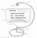
FIG. 1 is a perspective view of the invention deployed as a floating business card holder.
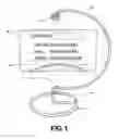
FIG. 2 is a perspective view of the magnetically suspended business card holder minus business cards.
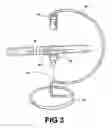
FIG. 3 is a perspective view of a holder for a common pen.
FIG. 4 is a perspective view of a dual-magnet version of the business card holder.
FIG. 5 is a perspective view of a photograph display embodiment.
DETAILED DESCRIPTION OF A PRESENTLY PREFERRED AND ALTERNATIVE EMBODIMENT OF THE INVENTION
Prior to proceeding to the more detailed description of the present invention it should be noted that, for the sake of clarity and understanding, identical components which have identical functions have been identified with identical reference numerals throughout the several views illustrated in the drawing figures.
Referring initially to FIG. 1, a levitating business card holder apparatus 10 is displayed. There is a base 12 from which there rises a cantilever support member 14, which has at its upper end a permanent magnet 16 attached hanging over the base 12. A holding tray 18 for business cards 24 has a magnet hidden behind the cards and attached to the holding tray 18, this magnet having an upward facing pole opposite that of magnet 16, so that there is a force pulling up on the holding tray 18.
More details of the business card holder apparatus are displayed in FIG. 2. An elongated metal rod is bent to form a base 12 and a cantilever support member 14. At the end of the support 14 is a powerful permanent magnet 16, for example a Neodymium type ring magnet, typically nickel plated and axially magnetized. The magnets can be single or multiple ones stacked. Another rigid wire structure 18 is fashioned into a two-sided business card holder for displaying business cards in two opposing directions. The uppermost part of the holder structure 18 is attached to permanent magnet or metallic object 20 in vertical alignment with the overhead magnet 16. If it is a magnet, the opposite pole needs to be facing that of the overhead magnet 16. A nearly invisible tether filament 22 is connected at one end to the base 12 and to holder structure 18 at the other end. This keeps the metal or magnet 20 from being drawn all the way up to overhead magnet 16. Preferably, the holder magnet 20 is positioned to be out of sight when cards are in the holder structure 18. The observer's eye is drawn to the gap below the overhead magnet 16, and there is the appearance of floating or levitating. While a bent metal rod is described above for both the base and support member, it is obvious that many other forms would also suffice.
FIG. 3 shows another application of the present invention, in this case supporting a common ordinary pen 30. This illustrates a distinguishing feature of this invention in that magnets or metal items do not have to be imbedded in the supported object. As above, the base 12 is extended and shaped to form the cantilever support 14 holding a permanent magnet 16 at the end. The pen holder is primarily a magnet 20 with attached prongs 26. The holder could also be in the form of a tray. The magnet 20 is restrained from being drawn all the way to the overhead magnet by the nearly invisible filament 22, which is attached to the base 12 and the magnet 20 with a length long enough to have a sufficient attraction of the magnets 16 and 20, but short enough to maintain a significant gap between the two. The tether filament could be a transparent nylon material.
FIG. 4 presents a variation of the business card holder. In this design, the base 12 is a separate somewhat solid base member with the curved support rod 14 attached to the base 12. In this instance, there are dual side-by-side magnets 17 at the upper end of the support rod 14. The business card holder 18 shown here consists of two semicircular trays back-to-back but closer at the top than at the bottom. Hidden behind and between the two trays of card holder 18 are dual magnets 21. A nearly invisible tether filament 22 connects to the support rod 14 near the base 12 and to a rod connecting the trays near the base.
FIG. 5 depicts an alternative embodiment of the present invention wherein the attraction and restraining means are aligned along a horizontal axis as opposed to the vertical axis in the prior drawings. There is a base 12 with two rigid rods 15 and 19 extending horizontally 180 degrees from one another first then curving vertically. At the distal end of rod 15, a pair of permanent magnets 17, or a rectangular magnet, is attached, either fixedly or rotatably. A planar frame 26 consists of two transparent layers. Attached to the opaque side at the center of one edge are two magnets or ferrous metal objects 21. At the opposite edge 180 degrees from the magnetic or metal objects 21, a nearly invisible tether filament 22 is attached, and the other end of filament 22 is secured to the end of one rigid rod 19. In operation, two photographs back-to-back are slid in between the two transparent layers. The nature of the dual or rectangular magnets is to prevent unassisted rotation. If an observer desires to tilt the photos or rotate to see the one on the other side, he/she does so by rotating the magnets which are frictionally restrained but can be rotated readily by a person.
While a presently preferred and various alternative embodiments of the present invention have been described in sufficient detail above to enable a person skilled in the relevant art to make and use the same, it should be obvious that various other adaptations and modifications can be envisioned by those persons skilled in such art without departing from either the spirit of the invention or the scope of the appended claims.
Claims
I claim:1. A display apparatus for suspending common office items in apparent defiance of gravity comprising:
a base capable of stable resting on a flat substantially horizontal surface;
a cantilever support member fixedly attached to said base with a distal end hovering over top portion of said base;
at least one first permanent magnet fixedly attached to said distal end of said cantilever support member;
a holder device shaped for supporting at least one said common office items;
at least one second permanent magnet fixedly attached to said holder device such that polarity of end facing up toward said first permanent magnet is opposite that of first permanent magnet; and
a substantially inconspicuous tether filament fixedly attached at one end to said base and at other end to said holder device.
2. The display apparatus, according to claim 1, wherein said common office item are themselves not magnetic.
3. The display apparatus, according to claim 1, wherein said cantilever support member is a substantially rigid rod arcuately shaped in a question mark pattern.
4. The display apparatus, according to claim 1, wherein said holder device is shaped and sized to retain business cards.
5. The display apparatus, according to claim 1, wherein said holder device is a tray capable of holding one of pens and paper clips.
6. The display apparatus, according to claim 1, wherein said permanent magnets are Neodymium type.
7. The display apparatus, according to claim 1, wherein said permanent magnets are positioned to be not visibly apparent when said display items are in said holder.
8. The display apparatus, according to claim 1, wherein said base and said cantilever support member are one continuous bent rod.
9. A photograph display apparatus giving an appearance of defying gravity comprising:
a) a base with substantially vertical sidearms separated by a predetermined distance;
b) a substantially transparent planar two-layer photograph holder;
c) a magnetic attraction means attached to distal end of one of said vertical sidearms;
d) a magnetically attractable means fixedly attached to center of edge of said transparent photograph holder adjacent said magnetic attraction means; and
e) a substantially inconspicuous tether filament having one end secured to distal end of said vertical sidearm not connected to said magnetic attraction means, wherein other end of said tether filament is secured to center of edge of said transparent photograph holder about 180 degrees from said magnetically attractable means.
10. The photograph display apparatus, according to claim 9, wherein said magnetically attractable means are at least two permanent magnets with opposite polarity facing said magnetic attraction means attached to said distal end.
11. The photograph display apparatus, according to claim 9, wherein said magnetic attraction means is at least two permanent magnets side-by-side rotatably attached to one of said vertical sidearms.
12. The photograph display apparatus, according to claim 9, wherein said magnetic attraction means is a rectangular magnet.
13. The photograph display apparatus, according to claim 9, wherein said magnetically attractable means is a rectangular ferrous metal bar.
14. The photograph display apparatus, according to claim 9, wherein said predetermined distance of separation is between about 2 inches and 18 inches.
Images & Drawings included:


Sources:
- United States Patent and Trademark Office - verify current appl. status at the USPTO↗
Recent applications in this class:
- » 20250113933 2025-04-10
DISPLAY UNITS FOR LITHOPHANES - » 20230255369 2023-08-17
NOVEL OPEN TYPE PHOTO FRAME - » 20190000246 2019-01-03
Display Stand - » 20160296044 2016-10-13
Wooden Image Display Assembly - » 20140124642 2014-05-08
STAND, SYSTEM, AND METHOD FOR DISPLAYING FRAMED PHOTOGRAPHS AT VARYING ELEVATIONS - » 20120273646 2012-11-01
Multi Dimensional Card Holder - » 20110088303 2011-04-21
Frame block for flat rectangular planar objects such as photographs - » 20090119965 2009-05-14
PICTURE FRAME - » 20090077851 2009-03-26
Lighted picture frame stand - » 20080129646 2008-06-05
MULTI-FUNCTION PICTURE FRAME