Method and apparatus for preparing thin film
US20080166491A1
2008-07-10
11/719,806
2005-09-30
✅ Patent granted
US 7,727,597 B2
2010-06-01
WO; PCT/JP2005/018101; 20050930
WO; WO2006/054393; 20060526
Nadine G Norton | Mahmoud Dahimene
2025-09-30
Abstract:
The present invention provides a method and an apparatus for preparing a silicon-containing solid film, which can form a thin film uniformly over a wide area. Raw-material fluid comprising a silane derivative and a hydrocarbon derivative is mixed with carrier fluid comprising carbon dioxide to form a supercritical condition. Further, an active-state is produced in the raw-material fluid of the supercritical fluid by a catalytic reaction with at least one metal catalyst selected from a group consisting of platinum, tungsten, cobalt, nickel, iron or an alloy of each of them. The fluid is blown to the substrate, thereby forming a silicon-containing solid film or a hydrocarbon-containing solid film on the substrate.
Inventors:
- Toshiyuki WATANABE 11 🇯🇵 Tokyo, Japan
- Eizo Watanabe 1 🇯🇵 Chiba, Japan
- Masato Sone 1 🇯🇵 Tokyo, Japan
- Yoshinori Matsuoka 1 🇯🇵 Hyogo, Japan
- Hideo Miyake 1 🇯🇵 Osaka, Japan
- Masayasu Iida 1 🇯🇵 Sakai-shi, Japan
- Eizo Watanabe 1 🇯🇵 Inzai-shi, Chiba, Japan
- Toshiyuki Watanabe 2 🇯🇵 Fuchu, Japan
- Masato Sone 1 🇯🇵 Fuchu, Japan
- Yoshinori Matsuoka 1 🇯🇵 Nishinomiya, Japan
- Hideo Miyake 1 🇯🇵 Sakai, Japan
- Masayasu Iida 1 🇯🇵 Sakai, Japan
Assignee:
- TOKYO UNIVERSITY OF AGRICULTURE AND TECHNOLOGY 3 🇯🇵 Fuchu-shi, Tokyo, Japan
- Eizo Watanabe 1 🇯🇵 Inzai-shi, Chiba, Japan
- ITEC CO., LTD. 1 🇯🇵 Sakai-shi, Osaka, Japan
- Tokyo University of Agriculture & Tech. 1 🇯🇵 Tokyo, Japan
- Itec Co., Ltd. 1 🇯🇵 Sakai-shi, Japan
- Eizo Watanabe 1 🇯🇵 Inzai-shi, Japan
Interested in similar patents?
Get notified when new applications in this technology area are published.
Classification:
B05D1/02 IPC
Processes for applying liquids or other fluent materials performed by spraying
H01L21/02115 » CPC main
Processes or apparatus adapted for the manufacture or treatment of semiconductor or solid state devices or of parts thereof; Manufacture or treatment of semiconductor devices or of parts thereof; Forming layers; Forming insulating materials on a substrate characterised by the type of layer, e.g. type of material, porous/non-porous, pre-cursors, mixtures or laminates characterised by the material of the layer the material being carbon, e.g. alpha-C, diamond or hydrogen doped carbon
C23C4/123 » CPC further
Coating by spraying the coating material in the molten state, e.g. by flame, plasma or electric discharge characterised by the method of spraying Spraying molten metal
C23C18/02 » CPC further
Chemical coating by decomposition of either liquid compounds or solutions of the coating forming compounds, without leaving reaction products of surface material in the coating; Contact plating by thermal decomposition
C23C18/08 » CPC further
Chemical coating by decomposition of either liquid compounds or solutions of the coating forming compounds, without leaving reaction products of surface material in the coating; Contact plating by thermal decomposition characterised by the deposition of metallic material
C23C18/1212 » CPC further
Chemical coating by decomposition of either liquid compounds or solutions of the coating forming compounds, without leaving reaction products of surface material in the coating; Contact plating by thermal decomposition characterised by the deposition of inorganic material other than metallic material inorganic material, e.g. non-oxide and non-metallic such as sulfides, nitrides based compounds; Oxides, e.g. ceramics Zeolites, glasses
C23C18/1279 » CPC further
Chemical coating by decomposition of either liquid compounds or solutions of the coating forming compounds, without leaving reaction products of surface material in the coating; Contact plating by thermal decomposition characterised by the deposition of inorganic material other than metallic material; Process of deposition of the inorganic material performed under reactive atmosphere, e.g. oxidising or reducing atmospheres
H01L21/02422 » CPC further
Processes or apparatus adapted for the manufacture or treatment of semiconductor or solid state devices or of parts thereof; Manufacture or treatment of semiconductor devices or of parts thereof; Forming layers; Forming inorganic semiconducting materials on a substrate; Substrates; Materials Non-crystalline insulating materials, e.g. glass, polymers
H01L21/0262 » CPC further
Processes or apparatus adapted for the manufacture or treatment of semiconductor or solid state devices or of parts thereof; Manufacture or treatment of semiconductor devices or of parts thereof; Forming layers; Forming inorganic semiconducting materials on a substrate; Formation types; Deposition types Reduction or decomposition of gaseous compounds, e.g. CVD
H01L21/02664 » CPC further
Processes or apparatus adapted for the manufacture or treatment of semiconductor or solid state devices or of parts thereof; Manufacture or treatment of semiconductor devices or of parts thereof; Forming layers; Forming inorganic semiconducting materials on a substrate; Special treatments Aftertreatments
B05B7/16 IPC
Spraying apparatus for discharge of liquids or other fluent materials from two or more sources, e.g. of liquid and air, of powder and gas incorporating means for heating the material to be sprayed
B05D5/00 IPC
Processes for applying liquids or other fluent materials to surfaces to obtain special surface effects, finishes or structures
B28B19/00 IPC
Machines or methods for applying the material to surfaces to form a permanent layer thereon
C23C20/00 IPC
Chemical coating by decomposition of either solid compounds or suspensions of the coating forming compounds, without leaving reaction products of surface material in the coating
C23C28/00 IPC
Coating for obtaining at least two superposed coatings either by methods not provided for in a single one of groups - or by combinations of methods provided for in subclasses and or
B05D7/00 IPC
Processes, other than flocking, specially adapted for applying liquids or other fluent materials to particular surfaces or for applying particular liquids or other fluent materials
Description
TECHNICAL FIELD
The present invention relates to a method for preparing a thin film, which forms a solid film on a surface of a substrate or the like thinly and uniformly.
BACKGROUND ART
There is a method using plasma CVD device as a conventionally known example of the method for forming a solid film on the surface of the substrate or the like (Patent Literature 1).
Patent Literature 1: Patent Publication Hei 6-60404
However, in the case of forming the thin film on the surface of the substrate or the like by using the plasma CVD device, there was a problem that the chamber must have the pressure of its interior area reduced. This restrains the size of the substrate and besides entails a difficulty in making the plasma to act evenly. There was another problem that the active-state to be to be produced and the raw material are low in concentration and the thin-film growth speed is slow due to the fact that the thin film is grown from the vapor phase.
Particularly, in the case of forming polysilicon film, there was a problem that the hydrogen produced from the raw material readily remains in the film with the result of being unable to exert a sufficient performance. Further, in recent years, a catalyst CVD method has been developed as a novel film-preparing method which can make a polysilicon film or a silicon nitride film on a glass substrate of low strain at a low temperature and a study is promoted on the way how to put it into practice. This catalyst CVD method can provide a polysilicon film having a mobility of electron and hole of about 0 to 50 cm2/v sec without the annealing treatment. However, the mobility of this film is not sufficient.
DISCLOSURE OF THE INVENTION
The present invention has been created from the viewpoint of those above facts and has an object of providing a method and an apparatus able to prepare a thin film of a high mobility uniformly at a low temperature over a wide area and at a high speed.
Means for Solving the Problem
In order to accomplish the above-mentioned object, the invention as set forth in claim 1 blows carrier fluid and raw-material fluid under a supercritical condition to a catalyst contained in a chamber so as to cause a contact reaction of the catalyst and the fluid by which reaction at least part of the raw-material fluid is decomposed and a substrate is exposed to an atmosphere of the active-state produced by the decomposition to form a solid film such as a silicon-containing solid film, a carbon-containing solid film and the like.
The present invention decomposes at least part of the raw-material fluid by the contact of the raw-material fluid with the catalyst to form a radical of a substance contained in the raw-material fluid so as to form a solid film on a surface of a substrate placed in the atmosphere of the radical.
Further, the hydrogen produced by the decomposition is promptly dissolved in supercritical fluid of the carrier fluid and therefore does not remain in the film. This forms the whole interior area of the chamber into a homogeneous atmosphere to result in the possibility of preparing the solid film over the entire substrate uniformly.
EFFECT OF THE INVENTION
The present invention places the carrier fluid and the raw-material fluid in the supercritical condition and introduces them into the chamber so as to bring them into contact with the device for producing the active-state (catalyst) within the chamber, thereby forming the radial of the element contained in the raw-material fluid with the result of being able to prepare a thin and minute solid film at a low temperature. Therefore, it was possible to obtain even on the glass or plastic substrate of low vitreous transition temperature a polysilicon film of good quality that was difficult to obtain conventionally.
Besides, in this case, the raw-material fluid has a concentration far higher than by the CVD device commonly used to result in enhancing the frequency of the occurrence of nucleus. Thus it is possible to prepare a homogeneous thin film free of pin holes in its entirety. Additionally, since there is no need of vacuuming the atmosphere within the chamber, the workability becomes excellent.
BRIEF DESCRIPTION OF THE DRAWINGS
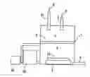
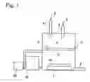
FIG. 1 is a schematic constructional view showing an example of the device for embodying the present invention.
MOST PREFERRED EMBODIMENT OF THE INVENTION
FIG. 1 shows an example of the device for embodying the present invention. There is arranged within a chamber 1 a device for producing an active-state 2 which partitions an interior area of the chamber 1. An inlet 4 for introducing raw-material fluid is positioned in one space 3 partitioned by this active-state production device 2 and a gas discharge-outlet 6 is disposed in the other space 5 in which a substrate 7 is positioned.
Used for the active-state production device 2 is a resistance-heating element which comes to be a catalyst, such as platinum, tungsten, cobalt, nickel, iron or an alloy of each of them. The resistance-heating element is employed by heating it up to a temperature of not more than 2000 degrees C. and arranging the reaction conditions. The catalyst may be heated through laser or electromagnetic wave. In this case, the temperature of 2000 degrees C. is a temperature at which carbon dioxide causes the plasma phenomenon and the catalyst is heated to a temperature region where the plasma phenomenon does not occur at a temperature exceeding the critical temperature of 31 degrees C. of carbon dioxide.
In addition, it is possible to utilize a platinum wire and an iron wire for the active-state production device 2.
In the case of forming a silicon-containing solid film, carbon dioxide 8 as carrier fluid is introduced from an inlet 41 for introducing the carrier fluid and at the same time a silane derivative is introduced from the raw-material fluid introduction inlet 4 into the chamber 1 to mix the carrier fluid and the raw-material fluid for use. The thus mixed fluid is brought into contact with the active-state production device 2 under a supercritical condition.
Further, used for the substrate 7 is a glass substrate, an aluminium substrate, a silicon substrate and a synthetic-resin substrate.
In the method for preparing solid film constructed as above, carbon dioxide 8 as the carrier fluid and the silane derivative 9 as a silicon source are supplied under the supercritical condition respectively into the chamber 1. If carbon dioxide 8 and the silane derivative 9 are introduced under the supercritical condition, both fluids are uniformly mixed to contact the active-state production device 2, thereby decomposing the silane derivative to silicon and hydrogen. This free silicon reaches the surface of the substrate 7 to form a thin, fine and solid crystalline silicon film 10. At this time, the carbon dioxide acts as a carrier gas but it is not the raw material of the free silicon.
The hydrogen gas produced by the decomposition of the raw-material fluid upon contact with the active-state production device 2 is smoothly dissolved into the carbon dioxide in supercritical condition and is discharged together with the introduced carbon dioxide through the gas discharge-outlet 6.
In the above-mentioned embodiment, carbon dioxide and silane derivative are introduced under supercritical condition independently into the chamber 1. However, the carbon dioxide and the silane derivative are mixed under supercritical condition and the resulting mixture may be introduced into the chamber 1.
On the other hand, in the case of forming a carbon-containing solid film, the carbon dioxide 8 as the carrier fluid is introduced through an inlet 41 for introducing the carrier fluid and a hydrocarbon derivative 9 as the raw-material fluid is introduced into the chamber 1 through the inlet 4 for introducing the raw-material. The carrier fluid and the raw-material fluid are mixed for use. The thus mixed fluid is brought into contact with the active-state production device 2 in supercritical condition.
As such, in the case of using the hydrocarbon derivative as the raw-material fluid, the hydrocarbon derivative is decomposed into carbon and hydrogen. This free carbon reaches the surface of the substrate 7 to form a thin, fine and solid polycrystalline diamond-like carbon film.
EMBODIMENT 1
First, a pre-washed glass substrate 7 is set within the chamber 1. Next, a turbo-molecular pump 55 and a rotary pump 56 are activated to reduce the pressure within the chamber 1 to about 1 to 2×10⁻⁶ Pa. While this state is maintained for about 5 minutes, particularly moisture and oxygen carried into the chamber are discharged. Further, the substrate 7 has its temperature heated to 200 degrees C. and held at this temperature.
Subsequently, the active-state production device (platinum-system catalyst) 2 is energized to raise its temperature up to about 1600 to 1800 degrees C. In this embodiment, it is set to 1800 degrees C. and is held in this state for 10 minutes.
Then silane (SiH4) is introduced from the reaction-gas control system into the chamber 1. More specifically, gas of raw material is supplied into chamber 1 by regulating the flow of supercritical carbon dioxide at 90 sccm/min and the flow of SiH4 at 9 sccm/min (100% silane). The chamber has its inner pressure kept at 5 Mpa and has its temperature retained at 50 degrees C. Film-formation is conducted at a speed of 80 nm/min for 1 minute to form a silicon film of about 40 nm thickness.
If the gas of raw material is supplied into the chamber 1 as such, the active-state production device 2 supplies to this gas, energy which allows this gas to make chemical reaction. This chemical reaction decomposes SiH4 to produce Si. As mentioned-above, silicon has deposited on the surface of the glass substrate 7 to form a silicon film at a high speed. The obtained silicon film has a diameter of crystalline particle controlled to a desired particle diameter not more than 100 nm (for example, fine particle diameter of about 1 to 2 nm) owing to the film-formation conditions because it was formed by the device of the present invention. Further, its content of hydrogen is so inhibited that the atom ratio is about 0.1 to 2.0 at %.
After it has been formed into the silicon film 10 as such, the reaction-gas control system regulates the flow of SiH4 gas to 0 and enables only carbon dioxide to continuously flow. And after this state is continued for 5 minutes, power supply to the active-state production device 2 is stopped to decrease its temperature. Subsequently, the flow of the carbon dioxide is regulated to 0 and further the interior area of the reaction chamber 51 has its pressure reduced to 1 to about 2×10⁻⁶ Pa. This state is maintained for about 5 minutes and particularly the SiH4 that was introduced into the chamber is discharged. Then the interior area of the chamber is returned to the atmospheric pressure and the glass substrate 7 is removed out of the camber 1. This film has a mobility of electron and hole of about 0 to 100 cm2/V·sec. without being subjected to the annealing treatment.
EMBODIMENT 2
First, a pre-washed glass substrate 7 is set within the chamber 1. Next, a turbo-molecular pump 55 and a rotary pump 56 are activated to reduce the pressure within the chamber 1 to about 1 to 2×10⁻⁶ Pa. While this state is maintained for about 5 minutes, particularly moisture and oxygen carried into the chamber are discharged. Further, the substrate 7 has its temperature heated to 200 degrees C. and held at this temperature.
Subsequently, the active-state production device (platinum-system catalyst) 2 is energized to raise its temperature up to about 1600 to 1800 degrees C. In this embodiment, it is set to 1800 degrees C. and is held in this state for 10 minutes.
Then dimethylaminosilane is introduced from the reaction-gas control system into the chamber 1. More specifically, gas of raw material is supplied into chamber 1 by regulating the flow of supercritical carbon dioxide at 90 sccm/min and the flow of dimethylaminosilane at 9 sccm/min (100% dimethylaminosilane). The chamber has its inner pressure kept at 5 Mpa and has its temperature retained at 50 degrees C. Film-formation is conducted at the speed of 80 nm/min for 1 minute to form a silicon film 10 of about 40 nm thickness.
If the gas of raw material is supplied into the chamber 1 as such, the active-state production device 2 decomposes the gas of raw material, thereby isolating an amino group and a methyl group which change to silane radicals. They make reaction, so that as mentioned-above, silicon has deposited on the surface of the glass substrate 7 to form a silicon film at a high speed. The obtained silicon film has a diameter of crystalline particle controlled to a desired particle diameter not more than 100 nm (for example, fine particle diameter of about 1 to 2 nm) owing to the film-formation conditions because it was formed by the device of the present invention. Further, its content of hydrogen is so inhibited that the atom ratio is about 0.1 to 2.0 at %.
After the silicon film 10 has been formed according to the above-mentioned procedures, the reaction-gas control system regulates the flow of dimethylaminosilane gas to 0 and enables only carbon dioxide to continuously flow. And after this state is continued for 5 minutes, power supply to the active-state production device 2 is stopped to decrease its temperature. Subsequently, the flow of the carbon dioxide is regulated to 0 and further the interior area of the reaction chamber 1 has its pressure reduced to about 1 to 2×10⁻⁶ Pa. This state is maintained for about 5 minutes and particularly the SiH4 that was introduced into the chamber is discharged. Then the interior area of the chamber is returned to the atmospheric pressure and the glass substrate 7 is removed out of the camber 1. This film had a mobility of electron and hole of about 0 to 150 cm2/V·sec. without being subjected to the annealing treatment.
EMBODIMENT 3
First, a pre-washed glass substrate 7 is set within the chamber 1. Next, the turbo-molecular pump 55 and the rotary pump 56 are activated to reduce the pressure within the chamber 1 to about 1 to 2×10⁻⁶ Pa. While this state is held for about 5 minutes, particularly moisture and oxygen carried into the chamber are discharged. Further, the substrate 7 has its temperature heated to 200 degrees C. and held at this temperature.
Subsequently, the active-state production device (platinum-system catalyst) 2 is energized to raise its temperature up to about 1600 to 1800 degrees C. In this embodiment, it is set to 1800 degrees C. and is held in this state for 10 minutes.
Then methane (CH4) is introduced from the reaction-gas control system into the chamber 1. More specifically, gas of raw material is supplied into chamber 1 by regulating the flow of supercritical carbon dioxide at 90 sccm/min and the CH4 flow at 9 sccm/min (100% methane). The chamber has its inner pressure kept at 5 Mpa and has its temperature retained at 50 degrees C. Film-formation is conducted at the speed of 80 nm/min for 1 minute to form a diamond-like carbon film (DLC) of about 40 nm thickness.
If the gas of raw material is supplied into the chamber 1 as such, the active-state production device 2 supplies to the gas of raw material, energy for enabling them to make a chemical reaction, thereby decomposing CH4 to produce C. Then, as mentioned-above, carbon has deposited on the surface of the glass substrate 7 to form a diamond-like carbon film 10 at a high speed. The obtained diamond-like carbon film has a diameter of crystalline particle controlled to a desired particle diameter not more than 100 nm (for example, fine particle diameter of about 1 to 2 nm) owing to the film-formation conditions because it was formed by the device of the present invention. Further, its content of hydrogen is so inhibited that the atom ratio is about 0.1 to 2.0 at %.
After it has been formed into the diamond-like carbon film 10 as such, the reaction-gas control system regulates the flow of CH4 gas to 0 and enables only carbon dioxide to continuously flow. And after this state is continued for 5 minutes, power supply to the active-state production device 2 is stopped to decrease its temperature. Subsequently, the flow of the carbon dioxide is also regulated to 0 and further the interior area of the reaction chamber 51 has its pressure reduced to about 1 to 2×10⁻⁶ Pa. This state is maintained for about 5 minutes and particularly the CH4 that was introduced into the chamber is discharged. Then the interior area of the chamber is returned to the atmospheric pressure and the glass substrate 7 is removed out of the camber 1.
EMBODIMENT 4
First, a pre-washed glass substrate 7 is set within the chamber 1. Next, the turbo-molecular pump 55 and the rotary pump 56 are activated to reduce the pressure within the chamber 1 to about 1 to 2×10⁻⁶ Pa. While this state is maintained for about 5 minutes, particularly moisture and oxygen carried into the chamber are discharged. Further, the substrate 7 has its temperature heated to 200 degrees C. and held at this temperature.
Subsequently, the active-state production device (platinum-system catalyst) 2 is energized to raise its temperature up to about 1600 to 1800 degrees C. In this embodiment, it is set to 1800 degrees C. and is held in this state for 10 minutes.
Then methanol (C2H5OH) is introduced from the reaction-gas control system into the chamber 1. More specifically, gas of raw material is supplied into chamber 1 by regulating the flow of supercritical carbon dioxide at 90 sccm/min and the flow of the methanol at 9 sccm/min (100% methanol). The chamber has its inner pressure kept at 5 Mpa and has its temperature retained at 50 degrees C. Film-formation is conducted at the speed of 80 nm/min for 1 minute to form a silicon film of about 40 nm thickness.
If the gas of raw material is supplied into the chamber 1 as such, the active-state production device 2 decomposes the gas of raw material, thereby first producing a carbon radical and then isolating hydrogen. They make a reaction. As a result, as mentioned-above, carbon has deposited on the surface of the glass substrate 7 to form a diamond-like carbon film 10 at a high speed. The obtained diamond-like carbon film has a diameter of crystalline particle controlled to a desired particle diameter not more than 100 nm (for example, fine particle diameter of about 1 to 2 nm) owing to the film-formation conditions because it was formed by the device of the present invention. Further, its content of hydrogen is so inhibited that the atom ratio is about 0.1 to 2.0 at %.
After the diamond-like carbon film 10 has been formed as such, the reaction-gas control system regulates the flow of methanol gas to 0 and enables only carbon dioxide to continuously flow. And after this state is continued for 5 minutes, power supply to the active-state production device 2 is stopped to decrease its temperature. Subsequently, the flow of the carbon dioxide is also regulated to 0 and further the interior area of the chamber 1 has its pressure reduced to about 1 to 2×10⁻⁶ Pa. This state is maintained for about 5 minutes and particularly the CH4 that was introduced into the chamber is discharged.
INDUSTRIAL AVAILABILITY
The present invention makes it possible to form a thin and fine silicon-containing solid film or carbon-containing solid film (DLC) on the surface of the substrate. Therefore, it is available for the field of producing various sorts of tools, jigs, friction-resistant materials, speaker vibration boars, wall materials for the nuclear fusion reactor, semi-conductor elements and the like.
Claims
1. A method of preparing a thin film comprising the steps of:
mixing raw-material fluid with carrier fluid within a chamber to form a supercritical condition;
producing active-state in the raw-material fluid of the supercritical fluid by a catalytic reaction; and
blowing the fluid to a substrate so as to form a solid film on the substrate.
2. The method of preparing a thin film as set forth in claim 1, where at least one metal selected from a group consisting of platinum, tungsten, cobalt, nickel, iron and an alloy of each of them is used for the catalyst.
3. The method of preparing a thin film as set forth in claim 1, where carbon dioxide is used as the carrier fluid and a silane derivative is utilized as the raw-material fluid, and
the carbon dioxide and the silane derivative are preliminarily mixed and then introduced into the chamber so as to form a silicon-containing solid film.
4. The method of preparing a thin film as set forth in claim 2, where carbon dioxide is used as the carrier fluid and a silane derivative is utilized as the raw-material fluid, and
the carbon dioxide and the silane derivative are preliminarily mixed and then introduced into the chamber so as to form a silicon-containing solid film.
5. The method of preparing a thin film as set forth in claim 1, where carbon dioxide is used as the carrier fluid and a silane derivative is utilized as the raw-material fluid, and
the carbon dioxide and the silane derivative are independently introduced into the chamber so as to form a silicon-containing solid film.
6. The method of preparing a thin film as set forth in claim 2, where carbon dioxide is used as the carrier fluid and a silane derivative is utilized as the raw-material fluid, and
the carbon dioxide and the silane derivative are independently introduced into the chamber so as to form a silicon-containing solid film.
7. The method of preparing a thin film as set forth in claim 1, where tetrakisdimethylaminosilane, trisdimethylaminosilane, bisdimethylaminosilane or dimethylaminosilane is used for the silane derivative to form a silicon-containing solid film.
8. The method of preparing a thin film as set forth in claim 2, where tetrakisdimethylaminosilane, trisdimethylaminosilane, bisdimethylaminosilane or dimethylaminosilane is used for the silane derivative to form a silicon-containing solid film.
9. The method of preparing a thin film as set forth in claim 3, where tetrakisdimethylaminosilane, trisdimethylaminosilane, bisdimethylaminosilane or dimethylaminosilane is used for the silane derivative to form a silicon-containing solid film.
10. The method of preparing a thin film as set forth in claim 4, where tetrakisdimethylaminosilane, trisdimethylaminosilane, bisdimethylaminosilane or dimethylaminosilane is used for the silane derivative to form a silicon-containing solid film.
11. The method of preparing a thin film as set forth in claim 5, where tetrakisdimethylaminosilane, trisdimethylaminosilane, bisdimethylaminosilane or dimethylaminosilane is used for the silane derivative to form a silicon-containing solid film.
12. The method of preparing a thin film as set forth in claim 6, where tetrakisdimethylaminosilane, trisdimethylaminosilane, bis-dimethylaminosilane or dimethylaminosilane is used for the silane derivative to form a silicon-containing solid film.
13. The method of preparing a thin film as set forth in claim 1, where silicon tetrachloride, trichlorosilan, dichlorosilan or monochlorosilan is used for a first reaction substance to form a silicon-containing solid film.
14. The method of preparing a thin film as set forth in claim 2, where silicon tetrachloride, trichlorosilan, dichlorosilan or monochlorosilan is used for a first reaction substance to form a silicon-containing solid film.
15. The method of preparing a thin film as set forth in claim 3, where silicon tetrachloride, trichlorosilan, dichlorosilan or monochlorosilan is used for a first reaction substance to form a silicon-containing solid film.
16. The method of preparing a thin film as set forth in claim 4, where silicon tetrachloride, trichlorosilan, dichlorosilan or monochlorosilan is used for a first reaction substance to form a silicon-containing solid film
17. The method of preparing a thin film as set forth in claim 5, where silicon tetrachloride, trichlorosilan, dichlorosilan or monochlorosilan is used for a first reaction substance to form a silicon-containing solid film
18. The method of preparing a thin film as set forth in claim 6, where silicon tetrachloride, trichlorosilan, dichlorosilan or monochlorosilan is used for a first reaction substance to form a silicon-containing solid film
19. The method of preparing a thin film as set forth in claim 1, where carbon dioxide is used as the carrier fluid and a silane derivative is utilized as the raw-material fluid, and
the carbon dioxide and the silane derivative are preliminarily mixed and then introduced into the chamber so as to form a carbon-containing solid film.
20. The method of preparing a thin film as set forth in claim 2, where carbon dioxide is used as the carrier fluid and a silane derivative is utilized as the raw-material fluid, and
the carbon dioxide and the silane derivative are preliminarily mixed and then introduced into the chamber so as to form a carbon-containing solid film.
21. The method of preparing a thin film as set forth in claim 1, where carbon dioxide is used as the carrier fluid and a hydrocarbon derivative is utilized as the raw-material fluid, and
the carbon dioxide and the hydrocarbon derivative are independently introduced into the chamber so as to form a carbon-containing solid film.
22. The method of preparing a thin film as set forth in claim 2, where carbon dioxide is used as the carrier fluid and a hydrocarbon derivative is utilized as the raw-material fluid, and
the carbon dioxide and the hydrocarbon derivative are independently introduced into the chamber so as to form a carbon-containing solid film.
23. The method of preparing a thin film as set forth in claim 1, wherein a hydrocarbon such as methane or an organic substance containing oxygen such as alcohol is used for the hydrocarbon derivative so as to form a carbon-containing solid film.
24. The method of preparing a thin film as set forth in claim 2, wherein a hydrocarbon such as methane or an organic substance containing oxygen such as alcohol is used for the hydrocarbon derivative so as to form a carbon-containing solid film.
25. The method of preparing a thin film as set forth in claim 19, wherein a hydrocarbon such as methane or an organic substance containing oxygen such as alcohol is used for the hydrocarbon derivative so as to form a carbon-containing solid film.
26. The method of preparing a thin film as set forth in claim 20, wherein a hydrocarbon such as methane or an organic substance containing oxygen such as alcohol is used for the hydrocarbon derivative so as to form a carbon-containing solid film.
27. The method of preparing a thin film as set forth in claim 21, wherein a hydrocarbon such as methane or an organic substance containing oxygen such as alcohol is used for the hydrocarbon derivative so as to form a carbon-containing solid film.
28. The method of preparing a thin film as set forth in claim 22, wherein a hydrocarbon such as methane or an organic substance containing oxygen such as alcohol is used for the hydrocarbon derivative so as to form a carbon-containing solid film.
29. An apparatus for preparing a thin film comprising an active-state production device (2) which is composed of a resistance heating element and partitions an interior area of a chamber (1) into two spaces, an inlet (4) for introducing raw-material fluid being positioned in one (3) of the spaces and a gas discharge-outlet (6) being arranged in the other (5) where a substrate (7) is disposed in the other space (5).
Images & Drawings included:
Sources:
- United States Patent and Trademark Office - verify current appl. status at the USPTO↗
Similar patent applications:
- » 20130034708
Method of preparing thin film, thin film, apparatus for preparing thin film, and electronic device including thin film - » 20160060167
Low temperature poly-silicon thin film preparation apparatus and method for preparing the same - » 20230209994
THIN-FILM TRANSISTOR, DISPLAY APPARATUS INCLUDING THE SAME, AND METHOD OF PREPARING THE THIN-FILM TRANSISTOR - » 20070054472
Apparatus for preparing oxide thin film and method for preparing the same - » 20050129860
Method and apparatus for preparing thin resin film - » 20240255388
METHODS AND APPARATUS FOR PREPARING THIN-FILM SPECIMENS - » 10394223
Polysilicon evaluating method, polysilicon inspection apparatus and method for preparation of thin film transistor - » 20240170579
Oxide thin film transistor, method for preparing same, and display apparatus - » 20180231828
INDIUM TIN OXIDE THIN FILM AND PREPARATION METHOD THEREOF, ARRAY SUBSTRATE AND DISPLAY APPARATUS COMPRISING THE SAME - » 20200266031
Method of preparing thin film sample piece and charged particle beam apparatus
Recent applications in this class:
- » 20250112036 2025-04-03
METHOD OF FORMING CARBON-CONTAINING FILM - » 20250104997 2025-03-27
METHOD OF PROCESSING SUBSTRATE, METHOD OF MANUFACTURING SEMICONDUCTOR DEVICE, RECORDING MEDIUM AND SUBSTRATE PROCESSING APPARATUS - » 20250046599 2025-02-06
DIAMOND-LIKE CARBON GAP FILL - » 20240420948 2024-12-19
SELECTIVE CARBON DEPOSITION ON TOP AND BOTTOM SURFACES OF SEMICONDUCTOR SUBSTRATES - » 20240363332 2024-10-31
AMORPHOUS CARBON FOR GAP FILL - » 20240347335 2024-10-17
METHOD FOR DEPOSITING AMORPHOUS CARBON FILM - » 20240304436 2024-09-12
SUBSTRATE PROCESSING METHOD AND SUBSTRATE PROCESSING APPARATUS - » 20240290610 2024-08-29
FILM FORMING METHOD AND FILM FORMING APPARATUS - » 20240282570 2024-08-22
RADICAL-ACTIVATED CARBON FILM DEPOSITION - » 20240222107 2024-07-04
METHODS AND APPARATUSES FOR CARBON DEPOSITION
Recent applications for this Assignee:
- » 20140020476 2014-01-23
Viscoelasticity measuring apparatus - » 20110233478 2011-09-29
SILICON FOR N-TYPE SOLAR CELLS AND A METHOD OF PRODUCING PHOSPHORUS-DOPED SILICON