Putting training device
US20080167136A1
2008-07-10
11/897,211
2007-08-29
✅ Patent granted
US 7,766,759 B2
2010-08-03
-
-
Nini Legesse
2027-08-29
Abstract:
A putting training device comprising a putter module which is selectively attachable and detachable to a putter and a target module. The putter module includes at least one indicia viewable when a users head is substantially vertically above the module. The putter module further includes a signaling element and the target module including a receiving element, and an indicating element. In use, the putter is directed towards the target module. A golf ball is struck in the direction of the target module and the indicating element alerts the user of impact condition.
Inventors:
- Richard Daniel Henwood 1 🇺🇸 Arroyo Grande, CA, United States
- William Henwood 1 🇺🇸 Norcross, GA, United States
Assignee:
- Solid Golf LLC 1 🇺🇸 Norcross, GA, United States
Interested in similar patents?
Get notified when new applications in this technology area are published.
Classification:
A63B69/36 IPC
Training appliances or apparatus for special sports for golf
A63B69/3614 » CPC main
Training appliances or apparatus for special sports for golf using electro-magnetic, magnetic or ultrasonic radiation emitted, reflected or interrupted by the golf club
A63B69/3685 » CPC further
Training appliances or apparatus for special sports for golf for putting Putters or attachments on putters, e.g. for measuring, aligning
A63B2220/40 » CPC further
Measuring of physical parameters relating to sporting activity Acceleration
A63B2220/80 » CPC further
Measuring of physical parameters relating to sporting activity Special sensors, transducers or devices therefor
A63B2220/805 » CPC further
Measuring of physical parameters relating to sporting activity; Special sensors, transducers or devices therefor Optical or opto-electronic sensors
Description
BACKGROUND
This device pertains to the field of golf in general and specifically to the art of putting. The art of putting consists of three major factors; posture and alignment at address to the ball, tempo of the putting stroke and striking the ball with the club face perpendicular to target. Many attempts have been made in the past to devise a product that could alert the user in real time to the condition of these factors while they are practicing the art of putting. Some prior art has been successful by; addressing only one or two of the factors, by incorporating the sensing means into a custom putter which is not legal for USGA tournament play, or by large expensive stationary devices.
SUMMARY OF THE INVENTION
A putting training device comprising a putter module which is selectively attachable and detachable to a putter and a target module. The putter module includes at least one indicia viewable when a users head is substantially vertically above the module. The putter module further including a signaling element and the target module including a receiving element, and an indicating element.
BRIEF DESCRIPTION OF THE DRAWINGS
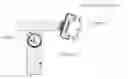
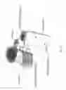
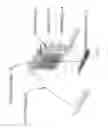
FIG. 1a is a front elevation view of the putter module;
FIG. 1b is a side elevation view of the putter module;
FIG. 1c is a rear elevation view of the putter module;
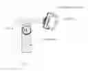
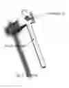
FIG. 2 is a front perimeter view of the target module;
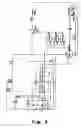
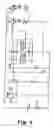
FIG. 3 is a schematic diagram of the putter module circuitry;
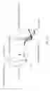
FIG. 4 is a perspective view of the shutter;
FIG. 5 is a perspective view of the aperture;
FIG. 6 is a schematic diagram of the target module circuitry.
DETAILED DESCRIPTION
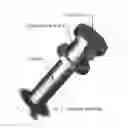
The putting training device described herein, address the three major factors, is small, portable, can be affixed to any right handed putter and will be affordable to most golfers. The benefit of this is that the golfer can practice their putting (at home, at the office or on a putting green) with a putter they are accustom to, remove the training device and go play with a putter that conforms to USGA rules. The device provides the user with instant feedback as to the temp of their putting stroke, the squareness to the target at impact with the ball and posture and alignment at address. The device consists of two modules, the Putter Module (FIGS. 1a, 1b, and 1c) and the Target Module (FIG. 2). Once the Putter Module (FIG. 1a, 1b, 1c) is affixed to the users putter and turned on, the user will notice a small green light 8 that appears on the top of the Putter module. This light has a limited viewing angle and the users head must be directly over it to be seen. This is the posture most experts in the field feel is required at address to the ball to achieve proper alignment to the target. Next, the user will aim the face of their putter towards the target. When the Putter Module (FIG. 1a, 1b, 1c) acquires the Target Module (FIG. 2), an amber light 14 will appear on the target. Next, the user will take a few practice strokes, observing the green light 8 on the Putter module (FIG. 1a, 1b, 1c). If the green light (LED) 8 is constant, the users' stroke is smooth and pendulum like. The aperture of green light 8 is tangent to the shutter (FIG. 4). If the green light is intermittent, the stroke is jerky, indicating over acceleration or deceleration. When the user is satisfied that their stroke is smooth, they will address the ball. Again, they will check their posture by observing the green light (LED) 8 on top of the Putting module (FIG. 1a, 1b, 1c) and check the squareness of the face of the putter to the target by observing the amber light 14 on the Target Module (FIG. 2). Next, they will stroke the putt towards the target. At the moment of impact, the amber light 14 will go out. If the putter was square to the target at impact, a green light (LED) 15 will appear on the Target module (FIG. 2). If the putter face was not square to the target, no light will appear. After a 2 second delay, the Target Module (FIG. 2) will again be ready to recognize an alignment signal from the Putter Module (FIG. 1a, 1b, 1c). The Putter Module (FIG. 1a, 1b, 1c) consists of: The mounting bracket 1, which attaches the module to the putter. The clamp 2, which holds the mounting bracket to the putter. The pivot 3, which allows the module to position itself perpendicular to the ground regardless of the lie angle of the putter. The aperture control 4, which varies the width of the beam projected by the target module (FIG. 1a) thru the lens 6. And the housing 7, which contains the printed circuit board (described in schematic drawing FIG. 3) and the battery door which allows for replacement of the battery. The Target Module (FIG. 2) consists of a stand 11, and housing 12. Within the housing 12 is a printed circuit board, described by the schematic drawing (FIG. 6). On the printed circuit board and appearing on the front face of the target are; an Amber LED 14, a Green LED 15 and an IR receiver 16. The target (FIG. 2) also has a target housing door 13 for easy replacement of the batteries.
Those versed in the art, will recognize the functions described in the schematic circuits shown in FIGS. 3 and 6. FIG. 3, the Putter Module, describes the following functions:
- C1-capacitor—conditions the power supply provided by the battery B1 thru switch S1.
- R8&9-resistors—provide a reference voltage to set the low battery indicator
- R1&D1—Green LED & current limiting resistor, provide the posture alignment indicator
- R2&R3—resistors, provide a reference voltage to set the sensitivity of X1
- X1—Piezo element, converts the mechanical energy of the shock of impact with the ball to an electrical signal
- uC1 —Microcontroller, signals a low battery condition by blinking D1, senses the impact of the ball via X1 and times the impact signal generated by 1C1
- 1C1—Quad nand gate, generates the alignment signal and impact signal impressed on the carrier signal sent by D2
- X2—Resonator, generates the 455 Khz. carrier signal
- Q1—Transistor, drives D2
- D2—Inferred emitting diode, sends the signal to the target
FIG. 6, the Target Module describes the following:
- PT1—Inferred detector, which received the signal from the Putter Module
- R1&R2—Resistors which provide a voltage reference for the low battery function
- U1—Microcontroller, interprets the signal received from the Putter Module via PT1
- And determines which LED to illuminate (Amber 14 and Green 15)
- Q1&Q2—transistors, which drive their respective LED's
- D1&D2—LED's which display the alignment signal and the proper impact signal
Claims
1. A putting training device comprising:
a putter module which is selectively attachable and detachable to a putter, and a target module;
said putter module including at least one indicia viewable when a users head is substantially vertically above the module, said putter module further including a signaling element; and,
said target module including a receiving element, and an indicating element.
2. The device of claim 1 wherein the signaling element comprises an infrared light source.
3. The device of claim 2 wherein the receiving element comprising an infrared receiver.
4. The device of claim 1 wherein the indicia is a light.
5. The device of claim 1 wherein an aperture allows adjustment of a beam width generated by said signaling element.
6. The device of claim 4 wherein the light is generated by a light emitting diode.
7. The device of claim 6 wherein a pendulum element intermediate said light and an outlet for said light from a housing physically occludes viewability of the light when a swing is off track or uneven in velocity.
8. The device of claim 1 wherein the said putter module is attachable to a shaft of said putter via a mounting bracket and clamp.
9. The device of claim 1 wherein the said putter module includes a pivot joint intermediate said mounting bracket and a housing containing said viewable indicia and said signaling element.
10. The device of claim 1 wherein the said target module includes a first and second light element of different colors.
11. A method of training a putting swing, comprising attaching a putter module to a putter, said putter module including at least one indicia viewable when a users' head is substantially vertically above the module, said putter module further including a signaling element; locating a target module including a receiving element to read said signaling element; directing said putter towards said target module a distance therefrom and striking a golf ball in the direction of said target module, wherein said indicia provides a visual signal to the user regarding a constant velocity of said putter during said striking step, and wherein said receiving element determines if the putter is substantially perpendicular to said target module at impact with said golf ball, said target module further including light elements to alert said user of the impact condition.
12. A putter comprising a shaft and a ball striking head and further including a putter module; said putter module including at least one indicia viewable when a users head is substantially vertically above the module, said putter module further including a signaling element; and, said target module including a receiving element, and an indicating element.
Images & Drawings included:
Sources:
- United States Patent and Trademark Office - verify current appl. status at the USPTO↗
Similar patent applications:
- » 20230041683
Golf Ball Returning Device from Both a Golf Net Training Device and a Putting Training Device - » 16594053
Putting training device - » 11192196
Putting training device and method - » 13187315
Golf putting training device - » 13743219
Golf putting training device - » 13529953
Putting training device - » 12456679
Golf putting training device - » 11543594
Golf putting training device - » 12112277
Magnetic golf putting training device - » 14086634
Putting training device
Recent applications in this class:
- » 20250205580 2025-06-26
ROTATIONALLY FIXED HOUSING FOR MULTI-AXIS MOTION SENSING, TELEMETRY, PROCESSING AND OTHER ELECTRONIC COMPONENTS OPERABLE TO SECURELY AFFIX TO A GOLF CLUB - » 20250195976 2025-06-19
Golf putter that indicates to the golfer when their eyes and head are optimally and consistently aligned to the putter-head, golf ball, and target-Line - » 20250108282 2025-04-03
GOLF CLUB HEAD - » 20250025761 2025-01-23
SYSTEMS AND METHODS FOR MEASURING AND/OR ANALYZING SWING INFORMATION - » 20240325845 2024-10-03
GOLF TRAINING APPARATUS AND/OR METHOD OF USE THEREOF - » 20240325844 2024-10-03
GOLF SWING ASSIST APPARATUS AND GOLF SWING ASSIST METHOD - » 20230356056 2023-11-09
GOLF TRAINING SYSTEM AND METHODS - » 20230277909 2023-09-07
Systems and methods for measuring and/or analyzing swing information - » 20220105410 2022-04-07
Systems and methods for measuring and/or analyzing swing information - » 20220088454 2022-03-24
SPORT APPARATUS WITH INTEGRATED SENSORS