Combination assembly of led and heat sink
US20080170371A1
2008-07-17
11/790,525
2007-04-26
Abstract:
A combination assembly of LED and heat sink includes a heat sink having a substrate and a plurality of fins, a circuit board provided on the substrate and at least one LED unit provided on the heat sink and electrically connected to the circuit board. The heat of the LED unit may be transmitted to the heat sink directly for heat transmission. The present invention has a greater heat transmission efficiency.
Assignee:
- TAI-SOL ELECTRONICS CO., LTD. 46 🇹🇼 TAIPEI CITY, Taiwan
Interested in similar patents?
Get notified when new applications in this technology area are published.
Classification:
F21V29/763 » CPC main
Protecting lighting devices from thermal damage; Cooling or heating arrangements specially adapted for lighting devices or systems; Cooling arrangements characterised by passive heat-dissipating elements, e.g. heat-sinks with fins or blades with essentially identical parallel planar fins or blades, e.g. with comb-like cross-section the planes containing the fins or blades having the direction of the light emitting axis
F21V29/503 » CPC further
Protecting lighting devices from thermal damage; Cooling or heating arrangements specially adapted for lighting devices or systems; Cooling arrangements characterised by the adaptation for cooling of specific components of light sources
H05K1/021 » CPC further
Printed circuits; Details; Thermal arrangements, e.g. for cooling, heating or preventing overheating; Cooling of mounted components Components thermally connected to metal substrates or heat-sinks by insert mounting
H05K1/021 » CPC further
Printed circuits; Details; Thermal arrangements, e.g. for cooling, heating or preventing overheating; Cooling of mounted components Components thermally connected to metal substrates or heat-sinks by insert mounting
H05K7/20509 » CPC further
Constructional details common to different types of electric apparatus; Modifications to facilitate cooling, ventilating, or heating characterised by the heat transfer by conduction from the heat generating element to a dissipating body Multiple-component heat spreaders; Multi-component heat-conducting support plates; Multi-component non-closed heat-conducting structures
F21Y2115/10 » CPC further
Light-generating elements of semiconductor light sources Light-emitting diodes [LED]
H01L33/648 » CPC further
Semiconductor devices with at least one potential-jump barrier or surface barrier specially adapted for light emission; Processes or apparatus specially adapted for the manufacture or treatment thereof or of parts thereof; Details thereof characterised by the semiconductor body packages; Heat extraction or cooling elements the elements comprising fluids, e.g. heat-pipes
H01L2224/73265 » CPC further
Indexing scheme for arrangements for connecting or disconnecting semiconductor or solid-state bodies and methods related thereto as covered by; Means for bonding being of different types provided for in two or more of groups; Location after the connecting process on different surfaces Layer and wire connectors
H05K1/182 » CPC further
Printed circuits; Printed circuits structurally associated with non-printed electric components associated with components mounted in the printed circuit board, e.g. insert mounted components [IMC]
H05K1/182 » CPC further
Printed circuits; Printed circuits structurally associated with non-printed electric components associated with components mounted in the printed circuit board, e.g. insert mounted components [IMC]
H05K3/0061 » CPC further
Apparatus or processes for manufacturing printed circuits; Laminating printed circuit boards onto other substrates, e.g. metallic substrates onto a metallic substrate, e.g. a heat sink
H05K3/0061 » CPC further
Apparatus or processes for manufacturing printed circuits; Laminating printed circuit boards onto other substrates, e.g. metallic substrates onto a metallic substrate, e.g. a heat sink
H05K2201/10106 » CPC further
Indexing scheme relating to printed circuits covered by; Details of components or other objects attached to or integrated in a printed circuit board; Types of components Light emitting diode [LED]
H05K2201/10106 » CPC further
Indexing scheme relating to printed circuits covered by; Details of components or other objects attached to or integrated in a printed circuit board; Types of components Light emitting diode [LED]
H01L2924/00 » CPC further
Indexing scheme for arrangements or methods for connecting or disconnecting semiconductor or solid-state bodies as covered by
H05K7/20 IPC
Constructional details common to different types of electric apparatus Modifications to facilitate cooling, ventilating, or heating
H05K7/20 IPC
Constructional details common to different types of electric apparatus Modifications to facilitate cooling, ventilating, or heating
Description
BACKGROUND OF THE INVENTION
1. Field of the Invention
The present invention relates generally to a light emitting diode (LED), and more particularly to a combination assembly of LED and heat sink, which has a greater performance in heat transmission.
2. Description of the Related Art
In present days, the high luminance LED produces high heat, and there is no fine solution to fix it yet.
U.S. Pat. No. 5,173,839 provides a heat transmission technique of a LED display. It provides a stack of a belt, an aluminum block, a belt and a heat sink under a LED chip to transmit the heat out. However, this technique provides three intermediates between the LED chip and the heat sink, which is the one performing heat transmission, that make the heat transmission rate is poor because the intermediates cause a greater heat resistance.
Taiwan Patent no. M295889 provides another heat transmission technique of LED. It provides a LED on a heat pipe. The LED includes a LED plastic insulating circuit board, a LED chip base, a LED heat chip and a LED lens. However, this technique provides the heat pipe, which has a high efficiency of heat transmission, to be the main for heat transmission, but there are also intermediates, the LED chip base and the LED plastic insulating circuit board, therebetween. These intermediates also cause the problem of high heat resistance and low heat transmission rate.
SUMMARY OF THE INVENTION
The primary objective of the present invention is to provide a combination assembly of LED and heat sink, which has a greater heat transmission performance for the LED.
According to the objective of the present invention, a combination assembly of LED and heat sink includes a heat sink having a substrate and a plurality of fins, a circuit board provided on the substrate and at least one LED unit provided on the heat sink and electrically connected to the circuit board. The heat of the LED unit may be transmitted to the heat sink directly for heat transmission. The present invention has a greater heat transmission efficiency.
BRIEF DESCRIPTION OF THE DRAWINGS
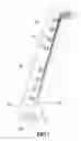
FIG. 1 is a perspective view of a first preferred embodiment of the present invention;
FIG. 2 is a top view of the first preferred embodiment of the present invention;
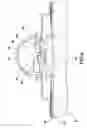
FIG. 3 is a sectional view along the 3-3 line of FIG. 2;
FIG. 4 is a sectional view of a second preferred embodiment of the present invention;
FIG. 5 is a sectional view of a third preferred embodiment of the present invention; and
FIG. 6 is a sectional view of the third preferred embodiment of the present invention, showing another package device.
DETAILED DESCRIPTION OF THE INVENTION
As shown in FIG. 1 to FIG. 3, a combination assembly of LED and heat sink 10 of the first preferred embodiment of the present invention mainly includes a heat sink 11, a circuit board 15 and a plurality of LED units 21.
The heat sink 11 includes a substrate 12 and a plurality of fins 13.
The circuit board 15 is mounted on the substrate 12.
The LED units 21 are mounted on the substrate 12 and electrically connected to the circuit board 15. Each of the LED units 21 mainly includes a LED chip 23, a wire 24 and a package device 25. The LED chip 23 has an anode 231 and a cathode 232. The cathode 232 is connected to the substrate 12. The wire 24 has an end connected to the anode 232 of the LED chip 23 and the other end connected to the circuit board 15. The package device 25 is an encapsulant, which is transparent or semi-transparent doped with fluorescence powder, encapsulating the LED chip 23 and the wire 24.
In practice operation of the first embodiment, an electronic driving device is connected to the circuit board 15 and the substrate 12. The cathodes 232 of the LED chips 23 are electrically connected to the substrate 12 through the wire 24 to form a common cathode that an electrical circuit board is formed. A power supply (not shown) is connected to the LED chips 23 through the wire 24 and the substrate 12 to make them lighting. A heat, which is generated by the LED chips 23 when they are lighting, will be transmitted to the substrate directly, and then transmitted to the fins 13 for heat transmission by the heat sink 11 with a grater size. This provides a high heat transmission efficiency for the LED chips 23.
As shown in FIG. 4, a combination assembly of LED and heat sink 30 of the second preferred embodiment of the present invention, which is similar to the assembly 10 of the first embodiment, except that:
Each of LED chips 43 has an anode 431 and a cathode 432 at a top thereof and has an insulating layer 433 at a bottom thereof. The anode 431 and the cathode 432 are electrically connected to the circuit board 35 through a wire 44.
The main difference between the second embodiment and the first embodiment is the LED chips 43 and how they mounted on the substrate 32. Except that, the rest structure, operation mode and functions of the second embodiment are as same as the first embodiment, and we will not describe it again.
As shown in FIG. 5, a combination assembly of LED and heat sink 50 of the third preferred embodiment of the present invention, which is similar to the assembly 10 of the first embodiment, except that:
Each of LED units 61 has a heat transmission base 62, a LED chip 63, two wires 64 and a package device 65. The heat transmission base 62 is mounted on a substrate 52, and the LED chip 63 is mounted on the heat transmission base 62. The wires are connected to an anode 631 and a cathode 632 of the LED chip 63 and a circuit board 55 respectively. The package device 65 encapsulates the LED chip 63, the wires 64 and the heat transmission base 62 therein.
The main difference between the third embodiment and the first embodiment is the LED chips 63, which has the heat transmission base 62 to be mounted on the substrate 52. Except that, the rest structure, operation mode and functions of the third embodiment are as same as the first embodiment, and we will not describe it again.
In addition, the third embodiment also may provide a lid-like package device 65′, as shown in FIG. 6, which has the same function of the encapsulant package device as described above.
In conclusion, the advantages of the present invention are:
Higher performance of heat transmission: to compare with the prior art, the present invention has no intermediate between the LED chips and the heat sink, so that the present invention has less heat transmission resistance. The present invention provides the LED chips mounted on the heat sink directly or provides a heat transmission base, which has a high heat transmission efficiency, between the LED chips and the heat sink that the heat of the LED chips may be transmitted to the heat sink directly or through the heat transmission base for heat transmission by the great size of the heat sink that has a greater performance of heat transmission than the prior art.
The description above is a few preferred embodiments of the present invention and the equivalence of the present invention is still in the scope of the claim of the present invention.
Claims
What is claimed is:1. A combination assembly of LED and heat sink, comprising:
a heat sink including a substrate and a plurality of fins;
a circuit board provided on the substrate; and
at least one LED unit provided on the heat sink and electrically connected to the circuit board.
2. The combination assembly of LED and heat sink as defined in claim 1, wherein there are two or more LED units, each of which includes a LED chip provided on the substrate, at least one wire having opposite ends connected to the LED chip and the circuit board respectively and a package device encapsulating the LED chip and the wire.
3. The combination assembly of LED and heat sink as defined in claim 2, wherein the LED chip has an anode connected to the wire and a cathode connected to the substrate.
4. The combination assembly of LED and heat sink as defined in claim 2, wherein the LED chip has an anode and a cathode at a top thereof and an insulating layer on a bottom thereof, wherein the insulating layer is mounted on the substrate, and the anode and the cathode are electrically connected to the circuit board through two of the wires.
5. The combination assembly of LED and heat sink as defined in claim 1, wherein there are two or more LED units, each of which includes a heat transmission base, a LED chip provided on the heat transmission base, two wires having opposite ends connected to an anode and a cathode of the LED chip and the circuit board respectively and a package device encapsulating the LED chip and the wire.
6. The combination assembly of LED and heat sink as defined in claim 2, wherein the package device is an encapsulant.
7. The combination assembly of LED and heat sink as defined in claim 5, wherein the package device is an encapsulant.
8. The combination assembly of LED and heat sink as defined in claim 1, wherein the package device is a lid.
Images & Drawings included:


Sources:
- United States Patent and Trademark Office - verify current appl. status at the USPTO↗
Recent applications in this class:
- » 20250172282 2025-05-29
POLYMER LUMINAIRE - » 20250035298 2025-01-30
ILLUMINATION DEVICE - » 20230400178 2023-12-14
LED LUMINAIRE THERMAL MANAGEMENT SYSTEM - » 20230003373 2023-01-05
Thermally conductive polymer luminaire - » 20220154922 2022-05-19
HEAT SINK FOR LIGHT FIXTURE FOR INDOOR GROW APPLICATION - » 20220099287 2022-03-31
LED luminaire thermal management system - » 20220090773 2022-03-24
LED lighting device - » 20220049844 2022-02-17
LED lighting device - » 20220026054 2022-01-27
LED LIGHTING DEVICE FOR CULTIVATED SURFACES - » 20210396381 2021-12-23
Elongated modular heatsink with coupled light source
Recent applications for this Assignee:
- » 20140345844 2014-11-27
HEAT SINK - » 20110045703 2011-02-24
Card connector capable of scraping - » 20100297886 2010-11-25
Card connector capable of detecting card entry - » 20100236754 2010-09-23
Airflow guider for use in heat sink - » 20100147493 2010-06-17
Heat-dissipating fin - » 20100120281 2010-05-13
Card connector capable of detecting card insertion - » 20100029135 2010-02-04
Antistatic card connector - » 20090244844 2009-10-01
Heat-dissipating module - » 20090244837 2009-10-01
Heat-dissipating module - » 20090231814 2009-09-17
Protective cap for thermal grease