Device for a screen
US20080172837A1
2008-07-24
11/578,776
2005-04-27
✅ Patent granted
US 7,849,562 B2
2010-12-14
WO; PCT/SE2005/000618; 20050427
WO; WO2005/106172; 20051110
William L. Miller
2026-03-13
Abstract:
The present invention relates to an arrangement in a pivotal screen or screen section for substantially continuous adjustability and parking of the screen in the desired position, the screen or screen section being provided with an upper hinge and a lower hinge, and the lower hinge being provided with a conicity for achieving a braking effect against pivoting of the parts in relation to one another.
Inventors:
- Dag Göranson 2 🇸🇪 Falkenberg, Sweden
- Örjan Göranson 2 🇸🇪 Falkenberg, Sweden
- Orjan Goranson 1 🇸🇪 Falkenberg, Sweden
Interested in similar patents?
Get notified when new applications in this technology area are published.
Classification:
A47G5/00 » CPC main
Screens ; Draught-deflectors
E05D7/1005 » CPC further
Hinges or pivots of special construction to allow easy separation or connection of the parts at the hinge axis by axially moving free pins, balls or sockets
E05D11/081 » CPC further
Additional features or accessories of hinges; Friction devices between relatively-movable hinge parts with both radial and axial friction, e.g. conical friction surfaces
E05D7/081 » CPC further
Hinges or pivots of special construction for use in suspensions comprising two spigots placed at opposite edges of the wing, especially at the top and the bottom, e.g. trunnions the pivot axis of the wing being situated near one edge of the wing, especially at the top and bottom, e.g. trunnions
E05Y2201/21 » CPC further
Constructional elements; Accessories therefore; Brakes; Disengaging means, e.g. clutches; Holders, e.g. locks; Stops; Accessories therefore Brakes
E05Y2201/25 » CPC further
Constructional elements; Accessories therefore; Brakes; Disengaging means, e.g. clutches; Holders, e.g. locks; Stops; Accessories therefore Force or torque adjustment therefore
E05Y2800/26 » CPC further
Details, accessories and auxiliary operations not otherwise provided for Form, shape
Y10T16/54 » CPC further
Miscellaneous hardware [e.g., bushing, carpet fastener, caster, door closer, panel hanger, attachable or adjunct handle, hinge, window sash balance, etc.]; Hinge including means to hold or retard hinged members against pivotal movement [e.g., catch]
Y10T16/54038 » CPC further
Miscellaneous hardware [e.g., bushing, carpet fastener, caster, door closer, panel hanger, attachable or adjunct handle, hinge, window sash balance, etc.]; Hinge including means to hold or retard hinged members against pivotal movement [e.g., catch] by friction On hinge pin or between surfaces surrounding hinge axis
Y10T16/5404 » CPC further
Miscellaneous hardware [e.g., bushing, carpet fastener, caster, door closer, panel hanger, attachable or adjunct handle, hinge, window sash balance, etc.]; Hinge including means to hold or retard hinged members against pivotal movement [e.g., catch] Pivoted
E05D11/08 IPC
Additional features or accessories of hinges Friction devices between relatively-movable hinge parts
E04B2/74 IPC
Walls, e.g. partitions, for buildings; Wall construction with regard to insulation; Connections specially adapted to walls Removable non-load-bearing partitions; Partitions with a free upper edge modular coordination
E05D11/10 IPC
Additional features or accessories of hinges Devices for preventing movement between relatively-movable hinge parts
Description
The present invention relates to an arrangement according to the preamble to appended claim 1.
An arrangement of the above-mentioned type is particularly usable in mobile screens that are exemplified in Swedish Registered Design 69367 which shows a fixed screen on a wheeled frame and two pivotal screens or screen parts on either side thereof. The prior art pivots or hinges have proved to suffer from various drawbacks, for example numerous moving parts that are excessively expensive, suffer from defective service life, etc. There is thus a need in the art for an improved hinge which is more economical and displays considerably longer service life, in particular from the functional viewpoint.
Thus, the task forming the basis of the present invention is to satisfy the above-outlined needs.
This task is solved by the present invention in the arrangement disclosed by way of introduction in that it has been given the characterising features as set forth in appended claim 1.
The present invention realises a hinge with a desirable braking function which moreover may be selected in a simple manner and thereby be adapted to different desirable conditions. After the selected braking function, this will, in principle, be constant and need not be adjusted while being used. Further, the constant braking effect will, in principle. be self-adjusting. A plurality of the parts included in the hinge entails simple assembly and thereby lower cost. Moreover, the present invention makes for superior design and hygienic form, which is of particular importance in the use of the product in the medical care sector and the like.
The present invention will be described in greater detail hereinbelow with reference to the accompanying drawings.
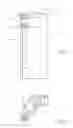
FIG. 1 is a view of an upper hinge section of the arrangement according to the present invention.
FIG. 2 shows the part illustrated in FIG. 1 from above.
FIG. 3 shows the part illustrated in FIG. 1 from beneath.
FIG. 4 is a view of an upper portion of the part illustrated in FIG. 1.
FIG. 5 is a view of a shaft included in the part illustrated in FIG. 1.
FIG. 6 is a front elevation of a further part of the arrangement according to the present invention.
FIG. 7 is a side elevation of the part according to FIG. 6.
FIG. 8 is a top plan view of the part according to FIG. 6.
FIG. 9 is a view of a part of the lower hinge section of the arrangement according to the present invention.
FIG. 10 is a front elevation of another part of the lower hinge section of the arrangement according to the present invention.
FIG. 11 is a side elevation of the part according to FIG. 10.
FIG. 12 is a top plan view of the part according to FIGS. 10 and 11.
In the different Figures, the same parts carry the same reference numerals. The embodiment of an arrangement according to the present invention illustrated in the Drawings will be described in greater detail in the practical application thereof on a mobile screen of the type which constitutes the subject matter of Swedish Registered Design 69367 which displays a fixed screen on a wheeled frame and two pivotal screens or screen sections on either side of the fixed screen.
The vertical edges of the fixed screen are provided with an aluminium profile 1 which is provided at the top with a plug 2 which appropriately may be manufactured from a plastic material. The plug 2 fits in the profile 1 and closes it upwardly. The plug 2 further has an anchorage 3 for an upper hinge shaft 4 which is cylindrical and fixed in a pivotal screen section by means of a cross pin 5. The plug 2 is shown from beneath in FIG. 3 and from the side in FIG. 4. Further, the hinge shaft 4 is shown in FIG. 5.
The arrangement according to the present invention moreover includes a lower hinge section which is shown in greater detail in FIGS. 6 to 12. In this lower hinge section, there is included a female part 6 which is secured on the profile 1 with the aid of a rivet nut 7 and a screw 8. The female part 6 has an upwardly directed conical hole 9 which is intended for a conical end portion 10 on a shaft 11 which is secured in the movable or pivotal screen section.
The female part 6 is shown in greater detail in FIGS. 10 and 11 and the male part 10, 11 is shown in greater detail in FIG. 9. The conicity of the hole 9 and on the end portion 10 may, for example, be 6° but it is naturally possible to select any desired conicity whatever depending on the properties that are desired as regards frictional forces or braking force. The female part 6 may be manufactured from reinforced nylon, but it naturally conceivable to employ many other types of materials, depending on the desired properties of the hinge.
As a result of an arrangement according to the present invention, it is possible to set the pivotal screen sections in any desired position whatever.
Many modifications are naturally possible without departing from the scope of the inventive concept as defined in the appended Claims.
Claims
1. An arrangement in a pivotal screen or screen section for substantially continuous adjustability and parking of the screen in the desired position, the screen or screen section being provided with an upper hinge and a lower hinge, wherein the lower hinge is provided with a conicity for achieving a braking effect against pivoting of the parts in relation to one another.
2. The arrangement as claimed in claim 1, wherein the lower hinge includes at least one male part and female part which are at least partly conical.
3. The arrangement as claimed in claim 2, wherein the male part is mounted on the screen or screen section, while the female part is mounted on a frame, or a wall for accommodating at least a part of the weight of the screen or screen section via the male part for achieving a desired frictional force between the male and the female part for counteracting pivoting of the parts in relation to one another.
Images & Drawings included:


Sources:
- United States Patent and Trademark Office - verify current appl. status at the USPTO↗
Similar patent applications:
- » 10469259
Screening device and drive means for the screening device and method of manual operating the screening device and a mounting for the screening device - » 20170336906
Combined fingerprint recognition touch screen device, method of driving the touch screen device, and electronic device including the touch screen device - » 20250039488
SCREEN PROJECTION METHOD, SCREEN PROJECTION DEVICE, SCREEN PROJECTION DISPLAY DEVICE, SCREEN PROJECTION SYSTEM AND MEDIUM - » 20140168013
Method for operating a handheld screening device and handheld screening device - » 20190138205
IMAGE DISPLAY METHOD OF A DUAL-SCREEN DEVICE, DUAL-SCREEN DEVICE, AND NON-TRANSITORY STORAGE MEDIUM - » 20130103328
SCREENING DEVICE FOR SEMICONDUCTOR DEVICES, SCREENING METHOD FOR SEMICONDUCTOR DEVICES AND PROGRAM THEREOF - » 20220215543
Information Processing Device, Screening Device, Information Processing Method, Screening Method, and Program - » 20180262793
Reverse Casting from a First Screen Device to a Second Screen Device - » 10653411
Screening device, such as a screen cylinder, and method of manufacture of the screening device - » 20150285898
Method for operating a handheld screening device and a handheld screening device
Recent applications in this class:
- » 20240306827 2024-09-19
ADJUSTABLE SCREEN SYSTEM FOR A WORK SURFACE - » 20240156283 2024-05-16
FOLDING ROOM DIVIDER - » 20230404298 2023-12-21
SHIELDING APPARATUS FOR A WORKSTATION - » 20220395115 2022-12-15
CONFIGURABLE MULTIFUNCTIONAL PRIVACY SCREEN - » 20220322849 2022-10-13
Flexible Personal Barrier Device - » 20210330098 2021-10-28
Screen attachment apparatus, kit for quick deployment of a screen apparatus that can provide biohazard protection and/or privacy and method of positioning a privacy screen adjacent a work surface - » 20210204725 2021-07-08
Adhesive Surface Divider - » 20200383501 2020-12-10
Privacy screen apparatus method of adjusting same - » 20180325289 2018-11-15
Portable and collapsible privacy shield - » 20170196380 2017-07-13
ROOM DIVIDER WITH SHOWER CURTAIN